Husqvarna ST 427 Owner Manual
Husqvarna ST 427 Manual
 |
View all Husqvarna ST 427 manuals
Add to My Manuals
Save this manual to your list of manuals |
Husqvarna ST 427 manual content summary:
- Husqvarna ST 427 | Owner Manual - Page 1
ST 424, ST 427, ST 430, ST 424T, ST 427T, ST 430T EN Operator's manual ES-MX Manual del usuario FR-CA Manuel d'utilisation 2-29 30-59 60-89 - Husqvarna ST 427 | Owner Manual - Page 2
Contents Introduction 2 Maintenance 16 Safety 5 Troubleshooting 26 Assembly 8 Transportation, storage and disposal 22 17 16 15 1. Fuel tank cap 2. Muffler 3. Oil fill/dipstick (for ST 424T/427T/430T only) 4. Battery cover 5. Discharge chute lever 6. Auger engagement 7. Drive speed lever - Husqvarna ST 427 | Owner Manual - Page 3
Discharge chute 26. Discharge chute deflector 27. LED light 28. Hook cover (ST 424T, ST 427T, ST 430T) 1 2 3 45 12 6 8 7 9 11 10 1. Adjustment snow thrower that is used to remove snow from the ground. Intended use This product can be used to remove snow manual. 876 - 011 - 11.05.2020 3 - Husqvarna ST 427 | Owner Manual - Page 4
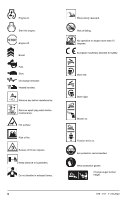
exhaust fumes. 4 Move slowly rearward. Risk of falling. No operation on slopes more than 10 degrees. European machinery directive for safety. Steer left. Steer right. Blower on. Traction drive on. Ear protection recommended. Wear protection gloves. Change auger bucket height. 876 - 011 - 11.05.2020 - Husqvarna ST 427 | Owner Manual - Page 5
a damaged product. Obey the maintenance schedule. Only do the maintenance work that you find an instruction about in this manual. An approved service center must do all other maintenance work. • This manual cannot include all situations that can occur when you use the product. Be careful and use - Husqvarna ST 427 | Owner Manual - Page 6
the operation of the product in some conditions. Safety instructions for operation • Do not put hands or feet near the cause. Vibration is generally a warning of trouble. • Stop the engine (motor) whenever overload the product capacity by attempting to clear snow at too fast a rate. • Never operate - Husqvarna ST 427 | Owner Manual - Page 7
product. • Always use heavy-duty slip-resistant boots with good ankle support while you operate the product. • Do not wear loose fitting a deformation or is damaged, speak to an approved Husqvarna service agent. WARNING: Read the warning instructions that follow before you use the product. 876 - - Husqvarna ST 427 | Owner Manual - Page 8
California Proposition 65 Proposition 65 Safety instructions for maintenance WARNING: Read the warning instructions that follow before you use the in this operator's manual. All other servicing must be done by an approved service agent. • Let an approved service agent do servicing on the product - Husqvarna ST 427 | Owner Manual - Page 9
Handle knobs (2) Locknut 3/8 (1) Locknut 3/18-16 (1) (ST 424/427/430 ) Cable holder (1) Shear pins ¼-20 x 1.81 (6) Locknuts ¼-20 (6) Locknut 5/16-18 (1) Locknut ¼-20 (1) Nylon washer (1) Carriage bolt 5/16-18 x 5/8 (1) Roll pin (1) Release - Husqvarna ST 427 | Owner Manual - Page 10
and tighten. 6. Attach the square retainer (I) with a locknut (H). 7. Put the cables through the hook cable slot. • For ST 424, ST 427, ST 430 use hook cable slot (C). • For ST 424T, ST 427T, ST 430T use hook cable slot (K). To install the discharge chute lever and the release cable 1. Push the knob - Husqvarna ST 427 | Owner Manual - Page 11
7. Adjust the left and right discharge chute cables. See To adjust the left and right discharge chute cables on page 24. To install the remote control for the discharge chute deflector 1. Attach the cable bracket (A) to the discharge chute with a carriage bolt (B) and a 5/16-18 locknut (D). Tighten - Husqvarna ST 427 | Owner Manual - Page 12
valve. Operate the product with the fuel switch in the OPEN position. OFF FUELCONTROL INSTRUCTIONS ON To start the engine, manual start 1. Put the ON/OFF key into the ignition slot (B). Do not turn the key. A B C D 2. For ST 424/427/430 only: Turn the fuel ON/OFF switch (C) to the ON position - Husqvarna ST 427 | Owner Manual - Page 13
key to the ON position. 1. To engage the auger blades, push the auger engagement (A) to the handle to engage the auger and throw snow. A A B C D 5. For ST 424/427/430 only: If the temperature is lower than -17 °C (0 °F), push the primer 3 times. See Product overview on page 2 for primer position - Husqvarna ST 427 | Owner Manual - Page 14
• Boost (A): to increase speed when the product is operated but does not throw snow, or to increase the distance that snow is thrown. • Fast (B): standard operation • Slow (C): to decrease the distance that snow is thrown, or to decrease engine noise To use the throttle control • Turn the throttle - Husqvarna ST 427 | Owner Manual - Page 15
Lower the drift cutters after use. To adjust the height of the auger bucket (for ST 424T/427T/430T only) 1. Push the lever (A) down. 2. Move the handles (B) up or for all moving parts to stop. 2. Remove snow and loose ice from the product. 3. Remove snow and loose ice from the base of the discharge - Husqvarna ST 427 | Owner Manual - Page 16
• Always throw snow downwind whenever possible. • On flat surfaces, like asphalt roads, raise the the engine oil level Replace the engine oil Do a check of and adjust the track tension (only ST 424T/ 427T/430T ) Make sure that there are no fuel or oil leaks Remove obstacles in the auger Lubricate - Husqvarna ST 427 | Owner Manual - Page 17
lights up the oil can symbol on the display after 20 hours of operation. The oil can symbol is then on for 2 hours or until a manual reset is done. A To reset the oil change reminder 1. Turn the ON/OFF key to the ON position, and keep it in the ON position - Husqvarna ST 427 | Owner Manual - Page 18
easy to start or does not operate correctly at idle speed. • To decrease the risk of unwanted material on the spark plug electrodes, obey these instructions: a) Make sure that the idle speed is correctly adjusted. b) Make sure that the fuel mixture is correct. 18 876 - 011 - 11.05.2020 - Husqvarna ST 427 | Owner Manual - Page 19
. If the scraper bar has damages or is worn on both edges, replace it. 3. If the edges of the augers are worn, contact an authorized service center to replace them. To replace the auger shear pins The auger shear pins protect the product from damage. The auger shear pins break if - Husqvarna ST 427 | Owner Manual - Page 20
The v-belts on your product are of special construction and should be replaced by original equipment manufacturer (OEM) belts available from your nearest service center. To use other belts than OEM can cause personal injury or damage to the product. WARNING: The belt replacement requires separation - Husqvarna ST 427 | Owner Manual - Page 21
to the frame (C) and remove the belt cover. C A B To remove the drive belt 1. Remove the auger belt (A). See To remove the auger belt (for ST 424/427/430 only) on page 22. 2. Remove the 9/16 in. pulley bolt (B) and remove the engine pulley (C) from the engine. A C D B E 3. Install the 9/16 - Husqvarna ST 427 | Owner Manual - Page 22
7. Move the auger brake arm and remove the auger belt (B) from around the auger brake arm. A B To remove the auger belt (for ST 424T/ 427T/430T only) 1. Remove the 5/16'' nut and the cable cover (E) from the frame. A B 4. Tighten the idler pulley nut (A). 5. Press and then release the drive - Husqvarna ST 427 | Owner Manual - Page 23
section. 4. Make sure that the belt is put in the auger pulley (E) groove correctly. 5. Install the 5/16'' bolts (C), and tighten (11-16 Nm). 6. For ST 424/427/430 only: Install the ¼'' bolts (D) and tighten (5-8 Nm). 7. Install the auger belt (B) on the engine pulley (A). Make sure that the belt is - Husqvarna ST 427 | Owner Manual - Page 24
If the adjustment does not resolve the problem, replace the auger belt. See To install the points straight forward, and the cables are tight. B To adjust the tension of the continuous tracks (for ST 424T/ 427T/430T only) Note: Tools that are necessary for this task: a 9/16" deep socket, a 9/16" - Husqvarna ST 427 | Owner Manual - Page 25
2. Remove the rear locknut (B) to give access to the adjustment nut. B A D C 10lb 3. Put a 5 kg (10 lbs) weight (C) on top of the continuous track, in the center between the 2 wheels. 4. Turn the adjustment nut (B) until the distance (D) between the continuous track and the steel plate is between - Husqvarna ST 427 | Owner Manual - Page 26
Troubleshooting Problem . Other causes. Inspect the starting procedures carefully in this manual. The fuel switch (if equipped) is in CLOSE ( ST 424T/427T/430T only) Contact an authorized service center. The fuel pump does not receive power. (For Contact an authorized service cen- ST 424T/427T - Husqvarna ST 427 | Owner Manual - Page 27
Problem Possible cause Solution Decreased power The spark plug cable is not connected. Connect the cable to the spark plug. The product throws too much snow. Decrease the speed and the width of the swath. The fuel tank cap is covered with ice or snow. Remove the ice and the snow service - Husqvarna ST 427 | Owner Manual - Page 28
Problem Possible cause Solution Loss of traction drive/ slowing of drive speed Loss of snow discharge or slowing of snow discharge The belt slips. The belt is worn. The belt is off the pulley. Adjust the cable. Adjust the belt. Check / replace the belt. Adjust - Husqvarna ST 427 | Owner Manual - Page 29
in use, send it to a Husqvarna dealer or discard it at a recycling location. • Discard the battery at a service center or discard it at a disposal location for used batteries. Technical data Technical data ST 424 ST 427 ST 430 ST 424T ST 427T ST 430T Dimensions Weight, with empty tanks - Husqvarna ST 427 | Owner Manual - Page 30
19 21 18 23 22 17 16 15 1. Tapa del depósito de combustible 2. Silenciador 3. Llenado de aceite/varilla de nivel (solo para ST 424T/427T/430T ) 4. Cubierta de la batería 5. Palanca del conducto de expulsión 6. Acoplamiento del barreno 7. Palanca de régimen de velocidad 8. Panel de control - Husqvarna ST 427 | Owner Manual - Page 31
24. Herramienta de limpieza 25. Conducto de expulsión 26. Deflector del conducto de expulsión 27. Luz LED 28. Cubierta del gancho (ST 424T, ST 427T y ST 430T) 1 2 3 45 12 6 8 7 9 11 10 1. Palanca de ajuste de la tolva sinfín 2. Interruptor de encendido/apagado (ON/OFF) de las manillas - Husqvarna ST 427 | Owner Manual - Page 32
¡Advertencia! Lea el manual de instrucciones. Motor en marcha. Arranque el motor. Motor apagado. Impulso. Rápido. Lento. Recordatorio de cambio de aceite. Mangos térmicos. Retire la llave antes realizar - Husqvarna ST 427 | Owner Manual - Page 33
no obedece las instrucciones y los símbolos, es posible que se produzcan daños y lesiones tanto graves como fatales. • No deseche este manual. Utilice las instrucciones para montar, operar y mantener el producto en buen estado. Utilice las instrucciones para la correcta instalación de piezas - Husqvarna ST 427 | Owner Manual - Page 34
fatales por asfixia o debido al monóxido de carbono. • Cuando utilice este producto, el motor crea un campo electromagnético. El campo electromagnético puede causar daños a implantes médicos. Hable con su médico y fabricante del implante antes de utilizar el producto. • No deje que un niño utilice - Husqvarna ST 427 | Owner Manual - Page 35
• Nunca agregue combustible a un motor en marcha o caliente. • Llene el depósito de combustible en el exterior, con máximo cuidado. Nunca llene el depósito de combustible en interiores • Nunca llene los recipientes de combustible dentro de un vehículo, en un camión o sobre la plataforma de un - Husqvarna ST 427 | Owner Manual - Page 36
provocar una explosión y causar lesiones. Si la batería tiene una deformación o está dañada, hable con un taller de servicio Husqvarna autorizado. ADVERTENCIA: Lea atentamente las instrucciones de advertencia siguientes antes de usar el producto. • Utilice gafas protectoras cuando esté cerca de las - Husqvarna ST 427 | Owner Manual - Page 37
Solo realice tareas de mantenimiento como se indica en el presente manual del usuario. Todas las demás tareas de mantenimiento se deben Palanca del conducto de expulsión Contratuerca de 3/8 (1) Contratuerca de 3/18-16 (1) (ST 424/427/430 ) Portacables (1) 876 - 011 - 11.05.2020 Muelle (1) Perno - Husqvarna ST 427 | Owner Manual - Page 38
Herramientas necesarias • Llave de 3/8" (1) • Llave de 7/16" (1) • Llave de 1/2" (1) • Enchufe de profundidad de 9/16" (1) A B Para instalar la empuñadura 1. Levante la empuñadura superior a la posición de funcionamiento. C 2. Ajuste la posición de la empuñadura a uno de los orificios (C). - Husqvarna ST 427 | Owner Manual - Page 39
7. Coloque los cables a través de la ranura para cables del gancho. • Para los modelos ST 424, ST 427 y ST 430 utilice la ranura para cables del gancho (C). • Para los modelos ST 424T, ST 427T y ST 430T utilice la ranura para cables del gancho (K). Instalación de la palanca del conducto de expulsi - Husqvarna ST 427 | Owner Manual - Page 40
Fijación de los pasadores de deslizamiento de recambio • Fije los pasadores de deslizamiento de recambio A B en la cubierta del control remoto o en la caja de la batería. C Funcionamiento Antes de arrancar el producto • Mantenga a las personas y animales alejados de la zona de trabajo. • - Husqvarna ST 427 | Owner Manual - Page 41
ósito antes de ponerlo en marcha. Uso del interruptor de combustible (solo para ST 424/427/430 ) • Gire el interruptor de combustible para abrir o cerrar posición OPEN (Abierto). OFF FUELCONTROL INSTRUCTIONS ON Para arrancar el motor con arranque manual 1. Coloque la llave de encendido/apagado - Husqvarna ST 427 | Owner Manual - Page 42
máquina en la página 30 para ver la posición del cebador. AVISO: No empuje el cebador demasiadas veces. Esto puede impedir que el motor arranque. Si el motor se ahoga, espere algunos minutos antes de intentar arrancar. No empuje el cebador. 6. Gire la llave de encendido/apagado (ON/OFF) para - Husqvarna ST 427 | Owner Manual - Page 43
A B C • Impulso (A): para aumentar la velocidad cuando el producto se maneja, pero no para quitar la nieve, ni para aumentar la distancia en que la nieve se expulsa. • Rápido (B): funcionamiento estándar • Lento (C): para reducir la distancia a la que la nieve se expulsa, o para disminuir el - Husqvarna ST 427 | Owner Manual - Page 44
que se expulsan a alta velocidad pueden causar lesiones. 3. Apriete la contratuerca (B). Ajuste de la altura de la tolva sinfín (solo para ST 424T/427T/430T ) 1. Empuje la palanca (A) hacia abajo. A B A B Para utilizar las cortadoras de deriva (si están equipadas) Utilice las cortadoras de deriva - Husqvarna ST 427 | Owner Manual - Page 45
las tuercas y tornillos. Compruebe el nivel de aceite del motor Cambie el aceite del motor Compruebe y ajuste la tensión de la banda (solo ST 424T/ 427T/430T ) Asegúrese de que no haya fugas de combustible o aceite Retire los obstáculos del barreno Lubrique los ganchos de interbloqueo 4 Diario - Husqvarna ST 427 | Owner Manual - Page 46
cables5 Compruebe la presión de los neumáticos (solo para ST 424/427/430 )6 Inspeccione y cambie las bujías antes de lata de aceite está encendido durante 2 horas o hasta que se reinicie de forma manual. A Restablecimiento del recordatorio de cambio de aceite 1. Gire la llave de encendido/apagado - Husqvarna ST 427 | Owner Manual - Page 47
5. Quite el tapón de vaciado de aceite, incline el producto y drene el aceite utilizado en el recipiente. 6. Vuelva a poner el producto en la posición de funcionamiento. 7. Coloque el tapón de vaciado de aceite y apriételo con la mano. 8. Llene el motor con aceite; consulte Para llenar el motor con - Husqvarna ST 427 | Owner Manual - Page 48
Para limpiar la batería y los terminales 1. Extraiga la batería. Consulte Para reemplazar la batería en la página 47. 2. Enjuague la batería con agua limpia y deje secar. 3. Limpie los terminales y los extremos de los cables de la batería con un cepillo hasta que estén brillantes. 4. Lubrique los - Husqvarna ST 427 | Owner Manual - Page 49
Para reemplazar los pasadores fusibles del propulsor A Los pasadores fusibles del propulsor protegen el producto de daños. Los pasadores fusibles del B propulsor se rompen si un objeto entra en contacto con las piezas móviles. C AVISO: Utilice únicamente los D pasadores fusibles originales - Husqvarna ST 427 | Owner Manual - Page 50
la cubierta de la correa. C A B Para retirar la correa de transmisión 1. Retire la correa del barreno (A). Consulte Retiro de la correa del barreno (solo para ST 424/427/430 ) en la página 51. 2. Retire el perno de la polea de 9/16 pulg. (B) y retire la polea del motor (C) del motor - Husqvarna ST 427 | Owner Manual - Page 51
la cubierta de la correa Consulte Para instalar la cubierta de la correa en la página 51. Retiro de la correa del barreno (solo para ST 424/427/430 ) 1. Retire la tuerca de 5/16" la tuerca y la cubierta del cable (E) del bastidor. A B C E D B 2. Instale el conducto de expulsión. Ajuste de la - Husqvarna ST 427 | Owner Manual - Page 52
retire la F correa del barreno (B) de alrededor del brazo del freno del barreno. Retiro de la correa del barreno (solo para ST 424T/427T/430T ) 1. Retire la tuerca de 5/16" la tuerca y la cubierta del cable (E) del bastidor. A B B C D E C F D E 2. Retire los pernos de 5/16" superiores de - Husqvarna ST 427 | Owner Manual - Page 53
A B 3. Mueva la polea tensora (B) en dirección de la correa del barreno para aumentar la tensión de la correa. Aléjela de la correa del barreno para disminuir la tensión de la correa. 4. Apriete la tuerca de la polea tensora (A). 5. Posicione el asistente a 3 m (10 pies) delante del producto para - Husqvarna ST 427 | Owner Manual - Page 54
que el conducto de expulsión apunte hacia delante y que los cables estén bien ajustados. Ajuste de la tensión de la banda continua (solo para ST 424T/427T/ 430T ) Tenga en cuenta: Las herramientas necesarias para esta tarea: un enchufe de profundidad de 9/16", una llave de 9/16" y un peso de 5 kg - Husqvarna ST 427 | Owner Manual - Page 55
• Utilice un cepillo para retirar las hojas, el césped y la suciedad. 876 - 011 - 11.05.2020 55 - Husqvarna ST 427 | Owner Manual - Page 56
causas. Inspeccione con cuidado los procedimientos de arranque de este manual. El interruptor de combustible (si está Coloque el interruptor servicio autorizado. va. (Solo para ST 424T/427T/430T ) La bomba de combustible no recibe alimentación. (Solo para ST 424T/ 427T/430T ) Comuníquese con un - Husqvarna ST 427 | Owner Manual - Page 57
Problema Causa posible Solución Potencia re- El cable de la bujía no está conecta- Conecte el cable a la bujía. ducida do. El producto lanza demasiada nieve. Disminuya la velocidad y el ancho de la hilera. La tapa del depósito de combustible está cubierta de hielo o nieve. Retire el hielo y - Husqvarna ST 427 | Owner Manual - Page 58
Problema Causa posible Solución Pérdida de tracción o ralentización de la velocidad de transmisión. Pérdida o ralentización de la descarga de nieve. La correa patina. La correa está desgastada. La correa se salió de la polea. El deflector del conducto está obstruido. Objetos extraños obstruyen - Husqvarna ST 427 | Owner Manual - Page 59
ST 424 ST 427 ST 430 ST 424T ST 427T ST 430T Dimensiones Peso con tanques vacíos, 140 145 150 160 165 170 kg Presión de funcionamien- N/D N/D N/D to máxima de los neumá- 18 18 20 ticos, psi Motor Marca Husqvarna Husqvarna Husqvarna Husqvarna Husqvarna Husqvarna Cilindrada - Husqvarna ST 427 | Owner Manual - Page 60
13 2 1 14 20 19 21 18 23 22 17 16 15 1. Bouchon du réservoir de carburant 2. Silencieux 3. Remplissage/jauge d'huile (pour ST 424T/427T/ 430T uniquement) 4. Couvercle de batterie 5. Levier de la goulotte d'éjection 6. Engagement de tarière 7. Levier de vitesse de l'entraînement 8. Panneau - Husqvarna ST 427 | Owner Manual - Page 61
re 24. Outil de nettoyage 25. Goulotte de décharge 26. Déflecteur de la goulotte d'éjection 27. Éclairage DEL 28. Passe-câbles (ST 424T, ST 427T, ST 430T) 1 2 3 45 12 6 8 7 9 11 1. Levier de réglage du godet à tarière 2. Interrupteur de marche/arrêt de poignée chauffante 3. Compteur horaire - Husqvarna ST 427 | Owner Manual - Page 62
Avertissement. Lire le manuel de l'opérateur. Moteur en marche. Démarrer le moteur. Arrêt du moteur. Très rapide. Rapide. Lent. Rappel de changement d'huile. Poignées chauffantes. Retirer la clé avant l'entretien. Déconnecter le câble de la bougie avant de commencer l'entretien. Surface chaude. - Husqvarna ST 427 | Owner Manual - Page 63
fabricant. • Le produit n'est pas réparé par un centre de service après-vente agréé ou par une autorité homologuée. Sécurité Définitions • Suivre les instructions de ce manuel. Respecter les symboles et les instructions de sécurité. Si l'opérateur ne respecte pas les instructions et les symboles - Husqvarna ST 427 | Owner Manual - Page 64
d'utiliser l'outil. • Ne pas laisser un enfant utiliser l'outil. Ne pas laisser une personne utiliser le produit sans connaître les instructions. • S'assurer de toujours surveiller les personnes avec des capacités physiques ou mentales réduites qui utilisent le produit. Un adulte responsable doit - Husqvarna ST 427 | Owner Manual - Page 65
Utiliser toujours des bottes antidérapantes robustes qui offrent un bon support aux chevilles lors de l'utilisation du produit. • Ne pas . Communiquer régulièrement avec un concessionnaire agréé ou à un centre de service après-vente agréé d'examiner le produit pour effectuer les réglages et les - Husqvarna ST 427 | Owner Manual - Page 66
endommagée peut engendrer une explosion et des blessures. Si la batterie est détériorée ou endommagée, communiquer avec un agent d'entretien Husqvarna agréé. AVERTISSEMENT : Lire les messages d'avertissement qui suivent avant d'utiliser l'outil. • Utiliser des lunettes de protection en cas de pr - Husqvarna ST 427 | Owner Manual - Page 67
en nylon(1) Boulon de carrosserie 5/16-18 x 5/8 (1) Goupille cylindrique (1) Levier de déverrouillage (1) Levier de la goulotte d'éjection Contre-écrou 3/8 (1) Contre-écrou 3/18-16 (1) Ressort (1) (ST 424/427/430 ) Support de câble (1) 876 - 011 - 11.05.2020 Boulon à épaulement ¼-20 (1) 67 - Husqvarna ST 427 | Owner Manual - Page 68
d'éjection sur la partie supérieure de la goulotte d'éjection. L'ouverture d'éjection doit pointer vers l'avant de l'appareil. 2. Placer la tête du rotateur (A) sur le support de la goulotte d'éjection (B). 3. Aligner les goupilles sous la tête du rotateur avec les trous dans le - Husqvarna ST 427 | Owner Manual - Page 69
travers le passecâbles. • Pour ST 424, ST 427, ST 430 utilisez le passe-câbles (C). • Pour ST 424T, ST 427T, ST 430T utilisez le passe-câbles (K). avec une goupille de fixation. 3. Fixer le câble de commande de vitesse sur le support (C) à l'aide de clés de 2 ½ po. Veiller à ce que le levier - Husqvarna ST 427 | Owner Manual - Page 70
4. Retirer la vis et l'écrou à ailettes (A) sur le levier coudé pour laisser le levier coudé se déplacer. A B Fixation des goupilles de tonte de rechange • Fixer les goupilles de tonte de rechange sur le couvercle de la commande à distance ou sur le boîtier de batterie. C Fonctionnement Avant - Husqvarna ST 427 | Owner Manual - Page 71
de carburant se trouve à la position OPEN (ouvert). OFF FUELCONTROL INSTRUCTIONS ON Démarrage du moteur (manuel) 1. Placer la clé ON/ 4. Tourner la clé ON/OFF (marche/arrêt) à la position ON (marche). 5. Pour ST 424/427/430 uniquement : Si la température est inférieure à -17 °C (0 °F), - Husqvarna ST 427 | Owner Manual - Page 72
A A B C D 5. Pour ST 424/427/430 uniquement : Si la température est inférieure à -17 °C (0 °F), appuyer trois fois sur la poire d'amorçage. Voir Présentation de la - Husqvarna ST 427 | Owner Manual - Page 73
Commande d'accélérateur Remarque : Si la neige est humide ou lourde, utiliser les modes rapide ou très rapide. La commande d'accélérateur permet de modifier le régime du moteur. Trois modes sont possibles : très rapide, rapide et lent. A B C Arrêt de la machine 1. Tourner la clé de contact à la - Husqvarna ST 427 | Owner Manual - Page 74
des blessures. 3. Serrer le contre-écrou (B). 3. Abaisser les coupe-bancs après usage. Réglage de la hauteur du godet à tarière (pour ST 424T/427T/430T uniquement) 1. Pousser le levier (A) vers le bas. A B A B Utilisation des coupe-bancs (selon équipement) Utiliser les coupe-bancs pour couper plus - Husqvarna ST 427 | Owner Manual - Page 75
Entretien Serrer les écrous et les vis. Vérifier le niveau d'huile moteur Vidanger l'huile moteur Vérifier et régler la tension de la chenille (pour ST 424T/427T/ 430T uniquement) S'assurer qu'il n'y a pas de fuites de carburant ou d'huile Retirer les obstacles dans la tarière. Lubrifier les crans - Husqvarna ST 427 | Owner Manual - Page 76
Entretien Lubrifier les attaches de câbles8 Vérifier la pression des pneus (pour ST 424/427/430 uniquement)9 Inspecter et remplacer la bougie d'allumage avant l'usage au début de saison et à intervalles recommandés. Quotidien À intervalles de À intervalles de À intervalles - Husqvarna ST 427 | Owner Manual - Page 77
la batterie. 1. Desserrer le bouton (A), puis basculer le bas du capot en direction du moteur. Soulever le couvercle de batterie hors de ses supports (B). B Batterie Entretien de la batterie Remarque : La batterie de votre produit est de type sans entretien. Ne pas ouvrir ou retirer les capuchons - Husqvarna ST 427 | Owner Manual - Page 78
de racleur est endommagée ou est usée des deux côtés, la remplacer. 3. Si les bords de la tarière sont usés, communiquer avec un centre de service agréé pour les remplacer. Remplacement des goupilles de tonte de la tarière La goupille de tonte protège le produit contre les dommages. Les - Husqvarna ST 427 | Owner Manual - Page 79
A C B A B D B C 5. Insérer la clé ON/OFF (marche/arrêt) dans le contact, puis brancher le câble d'allumage de la bougie. Remplacement des goupilles de tonte de la roue à ailette La goupille de tonte de la roue à ailette protège le produit contre les dommages. Les goupilles de tonte de la roue à - Husqvarna ST 427 | Owner Manual - Page 80
crou (A) qui fixe la tête du rotateur de goulotte (B) au support de montage (C) afin de retirer la goulotte d'éjection. B A d'origine disponibles auprès de votre centre de services le plus proche. L'utilisation de courroies autres que pour ST 424/427/430 uniquement) à la page 81. 80 876 - 011 - 11 - Husqvarna ST 427 | Owner Manual - Page 81
. 6. Installer le carter de la courroie. Voir Installation du carter de la courroie à la page 81. Retrait de la courroie de la tarière (pour ST 424/427/430 uniquement) 1. Déposer l'écrou 5/16 po et le cache-câble (E) du châssis. 876 - 011 - 11.05.2020 81 - Husqvarna ST 427 | Owner Manual - Page 82
et retirer la courroie de la tarière (B) du levier de frein de la tarière. Retrait de la courroie de la tarière (pour ST 424T/427T/430T uniquement) 1. Déposer l'écrou 5/16 po et le cache-câble (E) du châssis. 2. Déposer les boulons 5/16 po supérieurs des 2 côtés du châssis - Husqvarna ST 427 | Owner Manual - Page 83
est correctement positionnée dans la rainure de la poulie de la tarière (E). 5. Installer les boulons 5/16 po (C) et serrer (de 11 à 16 Nm). 6. Pour ST 424/427/430 uniquement : Installer les boulons ¼ po (D) et serrer (de 5 à 8 Nm). 7. Installer la courroie de la tarière (B) sur la poulie du moteur - Husqvarna ST 427 | Owner Manual - Page 84
4. Serrer l'écrou de blocage inférieur afin de le verrouiller en tension. Remarque : Il est également possible de tendre la courroie de la tarière en ajustant la poulie folle comme une option secondaire. Si le réglage du câble ne règle pas le problème, remplacer la courroie de la tarière. Voir - Husqvarna ST 427 | Owner Manual - Page 85
Réglage de la tension des chenilles continues (pour ST 424T/427T/430T uniquement) Remarque : Les outils nécessaires pour cette tâche : une douille profonde de 9/16 po, une clé de 9/16 po et un poids de 5 kg ( - Husqvarna ST 427 | Owner Manual - Page 86
de du démarreur ne s'engage pas. Inspecter le fusible du démarreur et le câblage. L'injecteur de carburant ne s'enclenche pas. (Pour ST 424T/427T/430T uniquement) Communiquer avec un centre de réparation agréé. La pompe à carburant n'est pas alimentée Communiquer avec un centre de réparation en - Husqvarna ST 427 | Owner Manual - Page 87
sont endommagées. Serrer tout le matériel de fixation. Remplacer les pièces endommagées. Si la vibration persiste, communiquer avec un centre de service agréé. Les poignées ne sont pas correctement positionnées. Assurez-vous que les poignées sont verrouillées en position. Les écrous du levier - Husqvarna ST 427 | Owner Manual - Page 88
Problème Cause possible Solution Perte de traction/ralentissement de la vitesse d'entraînement Perte de décharge ou ralentissement de la décharge de neige La courroie glisse. La courroie est usée. La courroie est sortie de la poulie. Le déflecteur de goulotte est obstrué. Des corps étrangers - Husqvarna ST 427 | Owner Manual - Page 89
ST 424 ST 427 ST 430 ST 424T ST 427T ST 430T Dimensions Poids, réservoirs vides 140 145 150 160 165 170 (kg) Pression maximale de S.O. S.O. S.O. fonctionnement des 18 18 20 pneus, en PSI Moteur Marque Husqvarna Husqvarna Husqvarna Husqvarna Husqvarna Husqvarna Cylindr - Husqvarna ST 427 | Owner Manual - Page 90
UPPER - CONTROL HARNESS BLK BLACK RED RED BLK/WHT BLACK & WHITE BLK/RED BLACK & RED RED/WHT RED & WHITE ORN ORANGE GRY GRAY WHT WHITE BLU BLUE YEL YELLOW IGNITION POSITION 1 2 3 ROTATION FUNCTION 0° OFF 45° RUN 85° START CONTACT G + M L + B + A L + B + S Connector label Circuit Description - Husqvarna ST 427 | Owner Manual - Page 91
E-GOV CHASSIS HARNESS ECU Connector label THROTTLE SIGNAL 5V + THROTTLE SIGNAL POWER, 12V, IGNITION GROUND CONSOLE CONN M START MOTOR BLK RED 23 RED 1 BATTERY 15 12 11 14 13 ENGINE 1 AC POWER - 2 20 AC POWER + 3 17 4 RPM OR PRIMARY COIL SIGNAL 5 8 POWER STARTER SOLENOID OUTPUT 6 7 BLK - Husqvarna ST 427 | Owner Manual - Page 92
LOWER - CHASSIS EFI HARNESS ECU Connector label ANALOG GROUND THROTTLE SIGNAL 5V + AC POWER GROUND POWER, 12V IGNITION THROTTLE SIGNAL CHARGING POWER GROUND M START MOTOR 24 RED BATTERY RED 1 ENGINE 1 AC POWER - 2 21 17 AC POWER + 3 18 GROUND 4 12 RPM OR PRIMARY COIL SIGNAL 5 8 POWER, - Husqvarna ST 427 | Owner Manual - Page 93
LCT EFI Throttle Body Harness THROTTLE BODY ECU ENGINE TEMP 1 SERVO OFF-SET POT 2 SERVO - 3 SERVO + 4 BATT - 5 INJECTOR - 6 ANA - 7 FUEL PRESSURE 8 ACTUATOR SIGNAL 9 ANA + 10 V + 11 PUMP - 12 BROWN GREY TAN PURPLE BLACK WHITE PINK BLUE YELLOW ORANGE RED GREEN THROTTLE ACTUATOR S S FUEL PRESSURE - Husqvarna ST 427 | Owner Manual - Page 94
EGOV Engine Harness ECU CHOKE 2B 1 CHOKE 2A 2 CHOKE 1B 3 CHOKE 1A 4 -5 B- 6 ENGINE TEMP 7 -8 AC2 9 AC1 10 THROTTLE 1A 11 THROTTLE 1B 12 THROTTLE 2A 13 THROTTLE 2B 14 ORANGE PINK YELLOW BLUE BLACK BROWN WHITE/RED BLACK ORANGE PINK BLACK WHITE CHOKE ACTUATOR 2B 2A 1B 1A ENGINE TEMP STATOR AC2 AC1 - Husqvarna ST 427 | Owner Manual - Page 95
- Husqvarna ST 427 | Owner Manual - Page 96
www.husqvarna.com Original instructions Instrucciones originales Instructions d'origine 1140723-49 2020-08-05
-
 1
1 -
 2
2 -
 3
3 -
 4
4 -
 5
5 -
 6
6 -
 7
7 -
8
-
9
-
10
-
11
-
12
-
13
-
14
-
15
-
16
-
17
-
18
-
19
-
20
-
21
-
22
-
23
-
24
-
25
-
26
-
27
-
28
-
29
-
30
-
31
-
32
-
33
-
34
-
35
-
36
-
37
-
38
-
39
-
40
-
41
-
42
-
43
-
44
-
45
-
46
-
47
-
48
-
49
-
50
-
51
-
52
-
53
-
54
-
55
-
56
-
57
-
58
-
59
-
60
-
61
-
62
-
63
-
64
-
65
-
66
-
67
-
68
-
69
-
70
-
71
-
72
-
73
-
74
-
75
-
76
-
77
-
78
-
79
-
80
-
81
-
82
-
83
-
84
-
85
-
86
-
87
-
88
-
89
-
90
-
91
-
92
-
93
-
94
-
95
-
96
 |
 |

ST 424, ST 427, ST 430, ST 424T, ST
427T, ST 430T
EN
Operator's manual
2-29
ES-MX
Manual del usuario
30-59
FR-CA
Manuel d’utilisation
60-89