IBM 2373 Hardware Maintenance Manual
IBM 2373 - ThinkPad T40 - Pentium M 1.4 GHz Manual
 |
View all IBM 2373 manuals
Add to My Manuals
Save this manual to your list of manuals |
IBM 2373 manual content summary:
- IBM 2373 | Hardware Maintenance Manual - Page 1
ThinkPad Computer Hardware Maintenance Manual February 2006 This manual supports: ThinkPad T40/T40p, T41/T41p, T42/T42p (MT 2373/2374/2375/2376/2378/2379) ThinkPad Dock II (MT 2877) - IBM 2373 | Hardware Maintenance Manual - Page 2
supports, be sure to read the general information under "Notices" on page 250. Second Edition (February 2006) © Copyright Lenovo 2006. Portions © Copyright International Business Machines Corporation 2006. All rights reserved. U.S. GOVERNMENT USERS - RESTRICTED RIGHTS: Our products and/or services - IBM 2373 | Hardware Maintenance Manual - Page 3
to do first 25 Related service information 27 Service Web site 27 Restoring the pre-installed system 27 Passwords 28 Power management 32 Checkout guide 35 Testing the computer 35 Detecting system information with PC-Doctor. . . 38 Power system checkout 39 ThinkPad T40/T40p, T41/T41p, T42 - IBM 2373 | Hardware Maintenance Manual - Page 4
123 1220 CPU 128 1230 Ultrabay Slim guide rail assembly for 14.1-in. LCD models 129 1240 Ultrabay Slim guide rail assembly for 15.0-in. LCD models cover for 15.0-in. LCD models 175 3010 ThinkPad Dock II PCI cover. . . . . . 182 3020 ThinkPad Dock II top cover 183 Locations 186 Front - IBM 2373 | Hardware Maintenance Manual - Page 5
14.1-in. LCD FRUs 220 15.0-in. LCD FRUs 230 Keyboard 235 Recovery CDs 237 Miscellaneous parts 243 AC adapters 246 Optional FRUs 247 Common parts list 248 Notices 250 Trademarks 252 Contents v - IBM 2373 | Hardware Maintenance Manual - Page 6
vi T40/T40p, T41/T41p, T42/T42p - IBM 2373 | Hardware Maintenance Manual - Page 7
computers. v The product-specific section includes service, reference, and product-specific parts information. Important This manual is intended for trained service personnel who are familiar with ThinkPad products. Use this manual along with the advanced diagnostic tests to troubleshoot problems - IBM 2373 | Hardware Maintenance Manual - Page 8
2 T40/T40p, T41/T41p, T42/T42p - IBM 2373 | Hardware Maintenance Manual - Page 9
call the Customer Support Center at 800- manual. Use the following strategy to prevent unnecessary expense for replacing and servicing FRUs: v If you are instructed to replace a FRU but the replacement does not correct the problem, reinstall the original FRU before you continue. v Some computers - IBM 2373 | Hardware Maintenance Manual - Page 10
error symptom is listed in the Symptom-to-FRU Index for the computer you are servicing. Diskette compatibility matrix The compatibility of each of the drives with and write Not compatible Safety notices: multilingual translations In this manual, safety notices appear in English with a page number - IBM 2373 | Hardware Maintenance Manual - Page 11
replacement, make sure all screws, springs, and other small parts are in place and are not left loose inside the computer. Verify this by shaking the computer and listening for rattling sounds. Metallic parts or metal flakes can cause electrical shorts. Avant de remettre l'ordinateur sous tension - IBM 2373 | Hardware Maintenance Manual - Page 12
unter dem Diskettenlaufwerk befindet, kann geringe Mengen Nickel und Cadmium enthalten. Sie darf nur durch die Verkaufsstelle oder den IBM Kundendienst ausgetauscht werden. Sie darf nicht zerlegt, wiederaufgeladen, kurzgeschlossen, oder Feuer oder Wasser ausgesetzt werden. Die Batterie kann schwere - IBM 2373 | Hardware Maintenance Manual - Page 13
(continuation of safety notice 2) Safety notices Alcune batterie di riserva contengono una piccola quantità di nichel e cadmio. Non smontarle, ricaricarle, gettarle nel fuoco o nell'acqua né cortocircuitarle. Smaltirle secondo la normativa in vigore (DPR 915/82, successive disposizioni e - IBM 2373 | Hardware Maintenance Manual - Page 14
Safety notices Safety notice 3 DANGER The battery pack contains small amounts of nickel. Do not disassemble it, throw it into fire or water, or short-circuit it. Dispose of the battery pack as required by local ordinances or regulations. Use only the battery in the appropriate parts listing when - IBM 2373 | Hardware Maintenance Manual - Page 15
Safety notices (continuation of safety notice 3) La batteria contiene piccole quantità di nichel. Non smontarla, gettarla nel fuoco o nell'acqua né cortocircuitarla. Smaltirla secondo la normativa in vigore (DPR 915/82, successive disposizioni e disposizioni locali). Quando si sostituisce la - IBM 2373 | Hardware Maintenance Manual - Page 16
Safety notices Safety notice 4 DANGER The lithium battery can cause a fire, an explosion, or a severe burn. Do not recharge it, remove its polarized connector, disassemble it, heat it above 100°C (212°F), incinerate it, or expose its cell contents to water. Dispose of the battery as required by - IBM 2373 | Hardware Maintenance Manual - Page 17
(continuation of safety notice 4) Safety notices La batteria di supporto e una batteria al litio e puo incendiarsi, esplodere o procurare gravi ustioni. Evitare di ricaricarla, smontarne il connettore polarizzato, smontarla, riscaldarla ad una temperatura superiore ai 100 gradi centigradi, - IBM 2373 | Hardware Maintenance Manual - Page 18
Entsorgung die örtlichen Bestimmungen für Sondermüll beachten. Der LCD-Bildschirm besteht aus Glas und kann zerbrechen, wenn er unsachgemäß behandelt wird oder der Computer auf den Boden fällt. Wenn der Bildschirm beschädigt ist und die darin befindliche Flüssigkeit in Kontakt mit Haut und Augen ger - IBM 2373 | Hardware Maintenance Manual - Page 19
Safety notice 6 DANGER Safety notices To avoid shock, do not remove the plastic cover that protects the lower part of the inverter card. Afin d'éviter tout risque de choc électrique, ne retirez pas le cache en plastique protégeant la partie inférieure de la carte d'alimentation. Aus Sicherheitsgrü - IBM 2373 | Hardware Maintenance Manual - Page 20
Safety notices Safety notice 7 DANGER Though the main batteries have low voltage, a shorted or grounded battery can produce enough current to burn personnel or combustible materials. Bien que le voltage des batteries principales soit peu élevé, le court-circuit ou la mise à la masse d'une batterie - IBM 2373 | Hardware Maintenance Manual - Page 21
Safety notice 8 DANGER Safety notices Before removing any FRU, power off the computer, unplug all power cords from electrical outlets, remove the battery pack, and then disconnect any interconnecting cables. Avant de retirer une unité remplaçable en - IBM 2373 | Hardware Maintenance Manual - Page 22
Safety information Safety information The following section presents safety information with which you need to be familiar before you service a ThinkPad computer. General safety Follow these rules to ensure general safety: v Observe good housekeeping in the area of the machines during and after - IBM 2373 | Hardware Maintenance Manual - Page 23
Safety information v After service, reinstall all safety shields, guards, labels, and ground wires. Replace any safety device that is worn or defective. v Reinstall all covers correctly before returning the - IBM 2373 | Hardware Maintenance Manual - Page 24
special safety precautions when you work with very high voltages; Instructions for these precautions are in the safety sections of maintenance ; such touching can cause personal injury and machine damage. v Do not service the following parts with the power on when they are removed from their - IBM 2373 | Hardware Maintenance Manual - Page 25
ThinkPad features or options not covered by this inspection guide . If any unsafe conditions are present, you must determine how serious the apparent hazard could be and whether you can continue without first correcting the problem every service task Power off the computer. Disconnect the power - IBM 2373 | Hardware Maintenance Manual - Page 26
with. Handling devices that are sensitive to electrostatic discharge Any computer part containing transistors or integrated circuits (ICs) should be such as those listed below, to provide protection that meets the specific service requirement. Note The use of a grounding system to guard against ESD - IBM 2373 | Hardware Maintenance Manual - Page 27
Safety information - Use the round ground prong of the ac plug on ac-operated computers. Grounding requirements Electrical grounding of the computer is required for operator safety and correct system function. Proper grounding of the electrical outlet can be verified by a certified electrician. - IBM 2373 | Hardware Maintenance Manual - Page 28
statement Laser compliance statement Some models of ThinkPad computer are equipped from the factory with an certified in the U.S. to conform to the requirements of the Department of Health and Human Services 21 Code of Federal Regulations (DHHS 21 CFR) Subchapter J for Class 1 laser products - IBM 2373 | Hardware Maintenance Manual - Page 29
the CD-ROM drive, the DVD-ROM drive, or any other optical storage device could result in exposure to hazardous laser radiation. There are no serviceable parts inside those drives. Do not open. Introduction 23 - IBM 2373 | Hardware Maintenance Manual - Page 30
Laser compliance statement A CD-ROM drive, a DVD-ROM drive, or any other storage device installed may contain an embedded Class 3A or Class 3B laser diode. Note the following: DANGER Emits visible and invisible laser radiation when open. Do not stare into the beam, do not view directly with optical - IBM 2373 | Hardware Maintenance Manual - Page 31
ThinkPad model that has the PC-Doctor® DOS diagnostics program. Some descriptions might not apply to your particular computer. Read this first Before you go to the checkout guide, be sure to read this section. Important notes v Only certified trained personnel should service the computer problem - IBM 2373 | Hardware Maintenance Manual - Page 32
Read this first __ 2. Date of service __ 3. Date on which the machine failed __ 4. Date of purchase indicate that the system was subjected to stress beyond normal use. Before checking problems with the computer, determine whether the damage is covered under the warranty by referring to the - IBM 2373 | Hardware Maintenance Manual - Page 33
into the CD or DVD drive, then restart the computer. 2. Following message is displayed: "Your computer originally included a Product Recovery program ... Reinstall the Product Recovery program? (Y/N) [ ]". 3. Press Y key. The service partition is created and loaded with the Product Recovery program - IBM 2373 | Hardware Maintenance Manual - Page 34
the recovery. Passwords As many as three passwords may be needed for any ThinkPad computer: the power-on password (POP), the hard-disk password (HDP), and no master HDP is available, neither Lenovo nor Lenovo authorized servicers provide any services to reset either the user or the master HDP, or to - IBM 2373 | Hardware Maintenance Manual - Page 35
been set and is known by the servicer: For T40/T40p, T41/T41p: 1. Turn on the computer and watch the lower left of the screen for a message saying, "To interrupt normal startup, press the blue Access IBM button." When that message appears, press the Access IBM - IBM 2373 | Hardware Maintenance Manual - Page 36
press the Access IBM button. The Rescue and Recovery screen opens. For models supporting the Passphrase function, press F1 while POP icon is appearing on the screen; then enter the POP. For the other models, enter the POP. Note: To check whether the ThinkPad computer supports the Passphrase function - IBM 2373 | Hardware Maintenance Manual - Page 37
Related service information IBM button. The Rescue and Recovery screen opens. For models supporting the Passphrase function, press F1 while HDP icon is appearing on the screen; then enter the master HDP. For the other models, enter the master HDP. Note: To check whether the ThinkPad computer supports - IBM 2373 | Hardware Maintenance Manual - Page 38
Related service information Power management To reduce power consumption, the computer has three power management modes: ACPI operating system, you can change the action of Fn+F4.s In certain circumstances, the computer goes into standby mode automatically: v If a "suspend time" has been set on the - IBM 2373 | Hardware Maintenance Manual - Page 39
Related service information computer enters the power-saving mode automatically. This default low-battery behavior is independent of the operating system; so if you have set the low-battery alarm, the computer may not do what you specified. It chooses either your setting or the default setting, - IBM 2373 | Hardware Maintenance Manual - Page 40
Related service information v If you are using the APM operating system and have battery becomes low, and the battery charge becomes critically low. When the power is turned on, the computer returns from hibernation mode and resumes operation. The hibernation file in the boot record on the hard disk - IBM 2373 | Hardware Maintenance Manual - Page 41
Checkout guide Checkout guide Use the following procedures as a guide in identifying and correcting problems with the ThinkPad computer. Note: The diagnostic tests are intended to test only ThinkPad products. The use of non-ThinkPad products, prototype cards, or modified options can lead to false - IBM 2373 | Hardware Maintenance Manual - Page 42
Checkout guide 3. Authenticating the digital signature takes about 15 seconds; then the ThinkPad computer will reboot into PC-DOS. 4. A batch file automatically starts up to prompt you through the process of creating diskettes. You are notified of how many - IBM 2373 | Hardware Maintenance Manual - Page 43
guide . v Video Adapter test supports only the LCD display on the ThinkPad computer. If you have an external monitor attached to your computer, detach it before running to the ThinkPad computer. 4. Run the applicable function test. 5. Follow the instructions on the screen. If there is a problem, PC - IBM 2373 | Hardware Maintenance Manual - Page 44
Checkout guide 6. To exit the test, select Quit - Exit Diag. To cancel the Info v VESA LCD Info Utility v Run External Tests v Surface Scan Hard Disk v Benchmark System v DOS Shell v Tech Support Form v Battery Rundown v View Test Log v Print Log v Save Log v Full Erase Hard Drive v Quick Erase Hard - IBM 2373 | Hardware Maintenance Manual - Page 45
guide Power system checkout To verify a symptom, do the following: 1. Turn off the computer. 2. Remove the battery pack. 3. Connect the ac adapter. 4. Check that power is supplied when you turn on the computer. 5. Turn off the computer turn on the computer. If you suspect a power problem, see the - IBM 2373 | Hardware Maintenance Manual - Page 46
Checkout guide Checking operational charging To check whether the battery charges properly during operation, use a discharged battery pack or a battery pack that has less than 50% of the total power remaining when installed in the computer. Perform operational charging. If the battery status - IBM 2373 | Hardware Maintenance Manual - Page 47
Checkout guide Note: Recharging will take at least 3 hours, even if the indicator the system board. Checking the backup battery Do the following: 1. Power off the computer, and unplug the ac adapter from it. 2. Turn the computer upside down. 3. Remove the battery pack (see "1010 Battery pack for 14 - IBM 2373 | Hardware Maintenance Manual - Page 48
Checkout guide 42 T40/T40p, T41/T41p, T42/T42p - IBM 2373 | Hardware Maintenance Manual - Page 49
ThinkPad T40/T40p, T41/T41p, 63 No-beep symptoms 63 LCD-related symptoms 64 Intermittent problems 65 Undetermined problems 65 FRU replacement notices 66 Screw notices 66 Retaining CPU 128 1230 Ultrabay Slim guide rail assembly for 14.1-in. LCD models 129 © Lenovo 2006. Portions - IBM 2373 | Hardware Maintenance Manual - Page 50
1240 Ultrabay Slim guide rail assembly for 15.0-in. LCD models 131 1250 VGA and cable assembly, hinges, and LCD cover for 15.0-in. LCD models 175 3010 ThinkPad Dock II PCI cover. . . . . . 182 3020 ThinkPad Dock II top cover 183 Locations 186 Front view 186 Rear view 188 Bottom view - IBM 2373 | Hardware Maintenance Manual - Page 51
page 50 v "FRU tests" on page 53 v "Fn key combinations" on page 54 Specifications The following table lists the specifications of the ThinkPad T40/ T40p, T41/T41p, T42/T42p series: Feature Processor Description T40/T40p series: v Intel® Pentium® M processor 1.3 GHz, 1-MB L2 cache v Intel Pentium - IBM 2373 | Hardware Maintenance Manual - Page 52
Product overview Feature Bus architecture Graphic memory chip Display Description T40/T40p series: v 400-MHz PSB (Processor System Bus) v 266-MHz DDR SDRAM (PC2100) v HUB link v PCI bus v LPC bus T41/T41p, T42/T42 series: v 400-MHz PSB v 333-MHz DDR SDRAM (PC2700) v HUB link v PCI bus v LPC bus T40 - IBM 2373 | Hardware Maintenance Manual - Page 53
-DIMM (PC2700) card × 1 v 512-MB DDR SDRAM SO-DIMM (PC2700) card × 1 v 1-GB DDR SDRAM SO-DIMM (PC2700) card × 1 (maximum of 2048 MB) v 242 bytes (continued) ThinkPad T40/T40p, T41/T41p, T42/T42p Series 47 - IBM 2373 | Hardware Maintenance Manual - Page 54
60.0 GB, 7200 rpm, 9.5 mm high, IDE interface v 80.0 GB, 4200 rpm, 9.5 mm high, IDE interface v 80.0 GB, 5400 rpm, 9.5 mm high, IDE interface Supported hard disk drives are depend on the model. Ultrabay Slim device T40/T40p, T41/T41p series: (standard) v DVD drive, 9.5 mm high v DVD/CD-RW combo - IBM 2373 | Hardware Maintenance Manual - Page 55
Battery AC adapter Preinstalled operating system Description T40/T40p series: v ThinkPad Dual-Band 11a/b Wi-Fi Wireless Mini PCI Adapter v Cisco 802.11b v Intel PRO/Wireless LAN 2100 3B Mini PCI Adapter v ThinkPad 11a/b/g Wireless LAN Mini PCI Adapter T42/T42p series: v Cisco Aironet Wireless 802. - IBM 2373 | Hardware Maintenance Manual - Page 56
Product overview Status indicators The system status indicators show the status of the computer, as follows: 1 29 28 27 26 25 24 23 2 8 3 2 50 T40/T40p, T41/T41p, T42/T42p - IBM 2373 | Hardware Maintenance Manual - Page 57
: The battery needs to be charged. When the indicator starts blinking orange, the computer beeps three times. Green: The computer is on and ready to use. This indicator stays lit whenever the computer is on and is not in standby mode. (continued) ThinkPad T40/T40p, T41/T41p, T42/T42p Series 51 - IBM 2373 | Hardware Maintenance Manual - Page 58
disk drive, the diskette drive, or the drive in the Ultrabay Slim device. When this indicator is on, do not put the computer into standby mode or turn off the computer. 6 Caps lock 7 Num lock 8 Bluetooth status R 9 Wireless status Note: Do not move the system while the green drive-in-use light - IBM 2373 | Hardware Maintenance Manual - Page 59
1. Diagnostics --> CPU/Coprocessor 2. Diagnostics --> Systemboard 3. If the docking station or the port replicator is attached to the ThinkPad computer, undock it. Place the computer on a horizontal surface, and run Diagnostics --> Other Devices --> HDD Active Protection Test. Note: Do not apply any - IBM 2373 | Hardware Maintenance Manual - Page 60
Full. 1. Turn on the computer and check the air turbulence service action is necessary. Touch Pad If enabling the TrackPoint does not correct the problem, continue with the following: v Interactive Tests --> Mouse If the Touch Pad does not work, check the configuration as specified in the ThinkPad - IBM 2373 | Hardware Maintenance Manual - Page 61
following drivers must be installed. v ThinkPad Power Management driver v OnScreen Display utility v Wireless device drivers Reserved. Switch a display output location v External monitor (CRT display) v Computer display and external monitor (LCD + CRT display) v Computer display (LCD) Note: For any - IBM 2373 | Hardware Maintenance Manual - Page 62
remove all ejectable devices connected to the ThinkPad computer, the ThinkPad Mini Dock, or the ThinkPad Port Replicator II. You cannot use it to detach the computer from the ThinkPad Mini Dock or the ThinkPad Port Replicator II. Note: This function is supported only in Windows 2000 and Windows XP - IBM 2373 | Hardware Maintenance Manual - Page 63
+F12 for hibernation in Windows 2000 or Windows XP, you must have the PM device driver installed on the computer. Turn the ThinkLight on or off. Note: This function is supported only on the ThinkPad computers that have the ThinkLight. The on or off status of the ThinkLight is shown on the screen for - IBM 2373 | Hardware Maintenance Manual - Page 64
the problem, put the original part back in the computer. Do not replace a nondefective FRU. This index can also help you determine, during regular servicing, what problems" on page 65. Note For a device not supported by diagnostic codes in the ThinkPad notebook computers, see the manual for - IBM 2373 | Hardware Maintenance Manual - Page 65
System board. 0192 System Security- IBM Embedded Security hardware tamper detected. System board. 0199 1. Run BIOS Setup Utility, System Security-IBM Security password retry count exceeded. tests of the keyboard and the auxiliary input device. ThinkPad T40/T40p, T41/T41p, T42/T42p Series 59 - IBM 2373 | Hardware Maintenance Manual - Page 66
. 0260 System timer error. 0270 Real-time clock error. 0271 Date and time error-Neither the date nor the time is set in the computer. 0280 Previous boot incomplete- Default configuration used. 02F5 DMA test failed. 02F6 Software NMI failed 02F7 Fail-safe timer NMI failed 1802 Unauthorized network - IBM 2373 | Hardware Maintenance Manual - Page 67
boot in Startup in Access IBM Predesktop Area. Boot from the Recovery CD and perform full recovery from it. 5. If item 4 failed, replace the hard disk drive. 1. Undock docking station or port replicator if it is attached to the ThinkPad computer, and place the computer on a horizontal surface. Do - IBM 2373 | Hardware Maintenance Manual - Page 68
Hibernation error. Fan error. Thermal sensing error. Authentication of system services failed. Press to resume. FRU or action, in System board. 1. Restore the system configuration to what it was before the computer entered hibernation mode. 2. If memory size has been changed, re-create - IBM 2373 | Hardware Maintenance Manual - Page 69
password prompt A hard-disk password is set. appears. Type the password and press Enter. The DOS full screen looks smaller than it should. Start the ThinkPad Configuration program and set the Screen expansion function. ThinkPad T40/T40p, T41/T41p, T42/T42p Series 63 - IBM 2373 | Hardware Maintenance Manual - Page 70
symptoms Important The TFT LCD for the notebook computer contains many thin-film transistors (TFTs). The presence of a small number of dots that are missing, discolored, or always lighted is characteristic of TFT LCD technology, but excessive pixel problems can cause viewing concerns. The LCD should - IBM 2373 | Hardware Maintenance Manual - Page 71
Non-ThinkPad devices b. Devices attached to the port replicator c. Printer, mouse, and other external devices d. Battery pack e. Hard disk drive f. External diskette drive g. DIMM h. CD-ROM and diskette drive in the Ultrabay i. PC Cards 4. Turn on the computer. 5. Determine whether the problem has - IBM 2373 | Hardware Maintenance Manual - Page 72
replacing parts. Read this section carefully before replacing any FRU. Screw notices Loose screws can cause a reliability problem. In the ThinkPad computer, this problem is addressed with special nylon-coated screws that have the following characteristics: v They maintain tight connections. v They - IBM 2373 | Hardware Maintenance Manual - Page 73
doing the following: 1. Install the ThinkPad Hardware Maintenance Diskette Version 1.73 or later and restart the computer. 2. From the main menu, select 1. Set System Identification. 3. Select 1. Add S/N data from EEPROM. Follow the instructions on the screen. ThinkPad T40/T40p, T41/T41p, T42/T42p - IBM 2373 | Hardware Maintenance Manual - Page 74
1.73 or later. 1. Insert the ThinkPad Hardware Maintenance Diskette Version 1.73 or later, and restart the computer. 2. From the main menu, select 6. Set ECA Information. 3. To read ECA information, select 2. Read ECA/rework number from EEPROM and follow the instruction. 4. To read box build date - IBM 2373 | Hardware Maintenance Manual - Page 75
from EEPROM, and follow the instruction on the screen. If the system board is being replaced, try to read the ECA information from the old system board and transfer the information to the new system. If the system board is inoperable, this will not be possible. ThinkPad T40/T40p, T41/T41p, T42 - IBM 2373 | Hardware Maintenance Manual - Page 76
presents directions and drawings for use in removing and replacing a FRU. Be sure to observe the following general rules: 1. Do not try to service any computer unless you have been trained and certified. An untrained person runs the risk of damaging parts. 2. Before replacing any FRU, review "FRU - IBM 2373 | Hardware Maintenance Manual - Page 77
Removing and replacing a FRU 1010 Battery pack for 14.1-in. LCD models DANGER Use only the battery specified in the parts list for your computer. Any other battery could ignite or explode. 1 (continued) ThinkPad T40/T40p, T41/T41p, T42/T42p Series 71 - IBM 2373 | Hardware Maintenance Manual - Page 78
Removing and replacing a FRU Holding the battery release lever in the unlocked position 2 , remove the battery pack 3 . 2 3 When installing: Install the battery pack along the slide rails on the left and right sides of the battery-pack slot. Then make sure that both battery latches, a and b , are - IBM 2373 | Hardware Maintenance Manual - Page 79
Battery pack for 15.0-in. LCD models DANGER Use only the battery specified in the parts list for your computer. Any other battery could ignite or explode. Holding the battery release lever in the unlocked position 1 , remove the battery pack 2 . 1 2 ThinkPad T40/T40p, T41/T41p, T42/T42p Series 73 - IBM 2373 | Hardware Maintenance Manual - Page 80
Removing and replacing a FRU 1030 Ultrabay Slim device Note Ultrabay Slim does not accept any of the following devices: v Ultrabay Plus devices v Ultrabay 2000 devices For devices compatible with the Ultrabay Slim bay, see "Optional FRUs" on page 247. Note: When you release the switch in step 1 , - IBM 2373 | Hardware Maintenance Manual - Page 81
disk is attached to the cover. Step Screw (quantity) 1 HDD screw (1) or security screw (1) Note: Use a 2.5-mm Allen wrench to remove the security screw. (continued) ThinkPad T40/T40p, T41/T41p, T42/T42p Series 75 - IBM 2373 | Hardware Maintenance Manual - Page 82
Removing and replacing a FRU 2 3 3 4 When installing: Make sure that the hard-disk connector is attached firmly. 76 T40/T40p, T41/T41p, T42/T42p - IBM 2373 | Hardware Maintenance Manual - Page 83
models" on page 71 v "1020 Battery pack for 15.0-in. LCD models" on page 73 Note: Loosen the screw 1 , but do not remove it. 2 1 (continued) ThinkPad T40/T40p, T41/T41p, T42/T42p Series 77 - IBM 2373 | Hardware Maintenance Manual - Page 84
Removing and replacing a FRU 3 4 3 When installing: Insert the notched end of the DIMM into the socket. Press the DIMM firmly, and pivot it until it snaps into the place. Make sure that it is firmly fixed in the slot and does not move easily. 78 T40/T40p, T41/T41p, T42/T42p - IBM 2373 | Hardware Maintenance Manual - Page 85
) M2 × 10 mm, flat-head, nylon-coated (3) M2 × 10 mm, flat-head, nylon-coated (1) Color Black Black Torque 0.245 Nm (2.5 kgfcm) 0.245 Nm (2.5 kgfcm) (continued) ThinkPad T40/T40p, T41/T41p, T42/T42p Series 79 - IBM 2373 | Hardware Maintenance Manual - Page 86
Removing and replacing a FRU Press the part indicated by the arrow 2 in the direction of the arrow. This releases the latches of the keyboard from the frame, so that the front side of the keyboard pops out. 2 Pull the keyboard a little in the direction of the arrow 3 , and then detach the connector - IBM 2373 | Hardware Maintenance Manual - Page 87
Removing and replacing a FRU When installing: 1. Attach the connector 1 . 1 2. Make sure that the keyboard edges, marked a in the figure, are under the frame. a a a (continued) ThinkPad T40/T40p, T41/T41p, T42/T42p Series 81 - IBM 2373 | Hardware Maintenance Manual - Page 88
that all the projections on the front side of the keyboard b are firmly attached under the frame. b b 5. Secure the keyboard from the underside of the computer, using the new screws provided with the keyboard. 82 T40/T40p, T41/T41p, T42/T42p - IBM 2373 | Hardware Maintenance Manual - Page 89
firmly, and pivot it until it snaps into the place. Make sure that it is firmly fixed in the slot and does not move easily. ThinkPad T40/T40p, T41/T41p, T42/T42p Series 83 - IBM 2373 | Hardware Maintenance Manual - Page 90
Removing and replacing a FRU 1080 Modem daughter card (MDC/MDC-2) For access, remove these FRUs in order: v "1010 Battery pack for 14.1-in. LCD models" on page 71 v "1020 Battery pack for 15.0-in. LCD models" on page 73 v "1060 Keyboard" on page 79 2 1 1 Step 1 Screw (quantity) M2 × 10 mm, flat - IBM 2373 | Hardware Maintenance Manual - Page 91
Removing and replacing a FRU Turn the card over 3 , and detach the modem connector 4. 3 4 When installing: Make sure that connector 4 and the connector on the underside of the card are firmly attached. ThinkPad T40/T40p, T41/T41p, T42/T42p Series 85 - IBM 2373 | Hardware Maintenance Manual - Page 92
Removing and replacing a FRU 1090 Bluetooth/Modem daughter card (BMDC/BMDC-2) For access, remove these FRUs in order: v "1010 Battery pack for 14.1-in. LCD models" on page 71 v "1020 Battery pack for 15.0-in. LCD models" on page 73 v "1060 Keyboard" on page 79 2 1 1 Step 1 Screw (quantity) M2 × - IBM 2373 | Hardware Maintenance Manual - Page 93
in direction of the arrow 5 . 3 5 4 When installing: Make sure that connector 4 , the jack 5 , and the connector on the underside of the card are firmly attached. ThinkPad T40/T40p, T41/T41p, T42/T42p Series 87 - IBM 2373 | Hardware Maintenance Manual - Page 94
Removing and replacing a FRU 1100 Palm rest or Palm rest with fingerprint sensor (for 14.1-in. LCD models) For access, remove these FRUs in order: v "1010 Battery pack for 14.1-in. LCD models" on page 71 v "1040 Hard disk drive" on page 75 v "1060 Keyboard" on page 79 Notes v In models with the - IBM 2373 | Hardware Maintenance Manual - Page 95
, nylon-coated (2) Black 0.204 Nm (2.0 kgfcm) 3a 4 - Special screw (1) Black 0.204 Nm (2.0 kgfcm) Note: Screw 3a is not available in models xxE and xxJ. (continued) ThinkPad T40/T40p, T41/T41p, T42/T42p Series 89 - IBM 2373 | Hardware Maintenance Manual - Page 96
other models, skip step 4 . 4 5 When installing: On a model with a touch pad, make sure that connector 4 is firmly attached. Note for LG-IBM models (Korea) in T40/T40p series: New palm rest FRU is shipped with the LG-IBM logo plate. When you replace the palm rest, you need to stick the LG - IBM 2373 | Hardware Maintenance Manual - Page 97
for the keyboard bezel with the fingerprint sensor. 1 1 1 Step Icon 1 1 Screw (quantity) M2 × 5 mm, flat-head, nylon-coated (6) Color Black Torque 0.245 Nm (2.5 kgfcm) (continued) ThinkPad T40/T40p, T41/T41p, T42/T42p Series 91 - IBM 2373 | Hardware Maintenance Manual - Page 98
Removing and replacing a FRU 2 2 2 2 2 Step Icon 2 2 Screw (quantity) Color M2 × 14 mm, bind-head, Black nylon-coated (6) Torque 0.245 Nm (2.5 kgfcm) 3 4 92 T40/T40p, T41/T41p, T42/T42p - IBM 2373 | Hardware Maintenance Manual - Page 99
Removing and replacing a FRU When installing: 1. Place the keyboard bezel so that the three latches are fixed in place 1 . 1 While inserting the three latches, align the top-left corner of the keyboard bezel as in figure a . a (continued) ThinkPad T40/T40p, T41/T41p, T42/T42p Series 93 - IBM 2373 | Hardware Maintenance Manual - Page 100
Removing and replacing a FRU 2. Press the left edges 2 and the front edges 3 of the keyboard bezel until the latches are snapped. 2 2 3 3 3. Attach the touch pad connector 4 . 4 (continued) 94 T40/T40p, T41/T41p, T42/T42p - IBM 2373 | Hardware Maintenance Manual - Page 101
Removing and replacing a FRU 4. Secure the keyboard bezel from the underside of the computer with the screws b and c . b b 1 c c 2 c c 5. Attach the keyboard. (continued) ThinkPad T40/T40p, T41/T41p, T42/T42p Series 95 - IBM 2373 | Hardware Maintenance Manual - Page 102
Removing and replacing a FRU 6. Secure the keyboard bezel from the underside of the computer with the screw d . This screw cannot be fastened properly without attaching keyboard. d 2 96 T40/T40p, T41/T41p, T42/T42p - IBM 2373 | Hardware Maintenance Manual - Page 103
the removal tool antenna RF connector (P/N: 08K7159) or pick the connectors with your fingers and gently unplug it in direction of the arrow 1 and 2 . 1 2 (continued) ThinkPad T40/T40p, T41/T41p, T42/T42p Series 97 - IBM 2373 | Hardware Maintenance Manual - Page 104
Removing and replacing a FRU 4 3 3 When installing: Plug in the wireless antenna cable as follows: Intel PRO/Wireless LAN 2100 3B Mini PCI Adapter or Intel PRO Wireless 2200BG Mini-PCI Adapter In case of the antenna jacks have the tabs, plug the gray antenna cable with the tab marked MAIN into jack - IBM 2373 | Hardware Maintenance Manual - Page 105
of the antenna jacks do not have the tabs, plug the gray cable to jack M, and the black cable to jack A. MAIN AUX MAIN AUX ThinkPad T40/T40p, T41/T41p, T42/T42p Series 99 - IBM 2373 | Hardware Maintenance Manual - Page 106
-Band 11a/b Wi-Fi Wireless Mini PCI Adapter, ThinkPad 11a/b/g Wireless LAN Mini PCI Adapter, or ThinkPad 11b/g Wireless LAN Mini PCI Adapter In case of the antenna jacks have the tabs, plug the gray antenna cable with the tab marked MAIN - IBM 2373 | Hardware Maintenance Manual - Page 107
(for 15.0-in. LCD models)" on page 91 1 Step 1 Screw (quantity) M2 × 10 mm, flat-head, nylon-coated (3) (continued) Color Black Torque 0.245 Nm (2.5 kgfcm) ThinkPad T40/T40p, T41/T41p, T42/T42p Series 101 - IBM 2373 | Hardware Maintenance Manual - Page 108
Removing and replacing a FRU Important In step 2 , insert the tip of the tool horizontally between the fan assembly and the CPU, as indicated by arrow a . Then slightly push the tool into the gap until the fan assembly comes off. Do not move the tool upward or downward to remove the fan assembly - IBM 2373 | Hardware Maintenance Manual - Page 109
assembly, long and for the fan assembly, long M10. Step 2b is for the fan assembly, short. Distortion of the fan assembly may cause a thermal problem. 2a 2b (continued) ThinkPad T40/T40p, T41/T41p, T42/T42p Series 103 - IBM 2373 | Hardware Maintenance Manual - Page 110
Removing and replacing a FRU 3 4 When installing: Make sure that the connector 4 is firmly attached. 104 T40/T40p, T41/T41p, T42/T42p - IBM 2373 | Hardware Maintenance Manual - Page 111
place it on the system board. Fan assembly, long M10 DOES NOT have the plastic sheet. a b Figure 2. Fan assembly, long a Figure 3. Fan assembly, long M10 ThinkPad T40/T40p, T41/T41p, T42/T42p Series 105 - IBM 2373 | Hardware Maintenance Manual - Page 112
Removing and replacing a FRU 1140 Backup battery for 14.1-in. LCD models DANGER Use only the battery specified in the parts list for your computer. Any other battery could ignite or explode. For access, remove these FRUs in order: v "1010 Battery pack for 14.1-in. LCD models" on page 71 v " - IBM 2373 | Hardware Maintenance Manual - Page 113
Removing and replacing a FRU 2 When installing: Make sure that the battery connector 2 is firmly attached. ThinkPad T40/T40p, T41/T41p, T42/T42p Series 107 - IBM 2373 | Hardware Maintenance Manual - Page 114
Removing and replacing a FRU 1150 Backup battery for 15.0-in. LCD models DANGER Use only the battery specified in the parts list for your computer. Any other battery could ignite or explode. For access, remove these FRUs in order: v "1020 Battery pack for 15.0-in. LCD models" on page 73 v " - IBM 2373 | Hardware Maintenance Manual - Page 115
Removing and replacing a FRU 2 When installing: Make sure that the battery connector 2 is firmly attached. ThinkPad T40/T40p, T41/T41p, T42/T42p Series 109 - IBM 2373 | Hardware Maintenance Manual - Page 116
Removing and replacing a FRU 1160 Speaker assembly For access, remove these FRUs in order: v "1010 Battery pack for 14.1-in. LCD models" on page 71 v "1020 Battery pack for 15.0-in. LCD models" on page 73 v "1040 Hard disk drive" on page 75 v "1060 Keyboard" on page 79 v "1100 Palm rest or Palm rest - IBM 2373 | Hardware Maintenance Manual - Page 117
Removing and replacing a FRU In step 3 , release the speaker cables from the cable guide. 2 4 3 When installing: Make sure that the connector 4 is firmly attached. Then route the cable as in 3 . ThinkPad T40/T40p, T41/T41p, T42/T42p Series 111 - IBM 2373 | Hardware Maintenance Manual - Page 118
Removing and replacing a FRU 1170 Keyboard bezel for 14.1-in. LCD models For access, remove these FRUs in order: v "1010 Battery pack for 14.1-in. LCD models" on page 71 v "1040 Hard disk drive" on page 75 v "1060 Keyboard" on page 79 v "1100 Palm rest or Palm rest with fingerprint sensor (for 14.1- - IBM 2373 | Hardware Maintenance Manual - Page 119
bezel. When installing: Make sure that all the latches marked a are firmly attached. Attach harness left ( b ), and then secure the keyboard bezel with the screws. ThinkPad T40/T40p, T41/T41p, T42/T42p Series 113 - IBM 2373 | Hardware Maintenance Manual - Page 120
Removing and replacing a FRU 1180 PC Card slot assembly for 14.1-in. LCD models For access, remove these FRUs in order: v "1010 Battery pack for 14.1-in. LCD models" on page 71 v "1040 Hard disk drive" on page 75 v "1060 Keyboard" on page 79 v "1100 Palm rest or Palm rest with fingerprint sensor ( - IBM 2373 | Hardware Maintenance Manual - Page 121
Removing and replacing a FRU 2 When installing: Make sure that the connector on the underside of the PC card slot 2 is firmly attached, and then secure the slot with the screws. ThinkPad T40/T40p, T41/T41p, T42/T42p Series 115 - IBM 2373 | Hardware Maintenance Manual - Page 122
Removing and replacing a FRU 1190 PC Card slot assembly for 15.0-in. LCD models For access, remove these FRUs in order: v "1020 Battery pack for 15.0-in. LCD models" on page 73 v "1040 Hard disk drive" on page 75 v "1060 Keyboard" on page 79 v "1110 Keyboard bezel or Keyboard bezel with fingerprint - IBM 2373 | Hardware Maintenance Manual - Page 123
installing: Make sure that the connector on the underside of the PC card slot 2 is firmly attached, and then secure the slot with the screws. ThinkPad T40/T40p, T41/T41p, T42/T42p Series 117 - IBM 2373 | Hardware Maintenance Manual - Page 124
Removing and replacing a FRU 1200 LCD assembly for 14.1-in. LCD models For access, remove these FRUs in order: v "1010 Battery pack for 14.1-in. LCD models" on page 71 v "1040 Hard disk drive" on page 75 v "1060 Keyboard" on page 79 v "1090 Bluetooth/Modem daughter card (BMDC/BMDC-2)" on page 86 v " - IBM 2373 | Hardware Maintenance Manual - Page 125
detach the LCD connector 4 . When installing: Make sure that the bracket 3 and the connector 4 are firmly attached, and then secure them with the screw. (continued) ThinkPad T40/T40p, T41/T41p, T42/T42p Series 119 - IBM 2373 | Hardware Maintenance Manual - Page 126
Removing and replacing a FRU 5 Step 5 Screw (quantity) M2 × 10 mm, flat-head, nylon-coated (1) (continued) Color Black Torque 0.245 Nm (2.5 kgfcm) 120 T40/T40p, T41/T41p, T42/T42p - IBM 2373 | Hardware Maintenance Manual - Page 127
Removing and replacing a FRU Release the antenna cables from the cable guide 6 . 6 6 6 6 6 6 When installing: Make sure that the antenna cables are correctly routed and securely in place. (continued) ThinkPad T40/T40p, T41/T41p, T42/T42p Series 121 - IBM 2373 | Hardware Maintenance Manual - Page 128
Removing and replacing a FRU 7 7 When installing: Make sure that the security keyhole which is on the left-rear corner of the base cover and the keyhole of the bracket inside are aligning firmly. 122 T40/T40p, T41/T41p, T42/T42p - IBM 2373 | Hardware Maintenance Manual - Page 129
91 v "1120 Mini PCI adapter" on page 97 1 1 Step 1 Screw (quantity) M2 × 10 mm, flat-head, nylon-coated (2) (continued) Color Black Torque 0.245 Nm (2.5 kgfcm) ThinkPad T40/T40p, T41/T41p, T42/T42p Series 123 - IBM 2373 | Hardware Maintenance Manual - Page 130
Removing and replacing a FRU 2 3 Step 2 Screw (quantity) M2 × 12 mm, flat-head, nylon-coated (1) Color Black Torque 0.245 Nm (2.5 kgfcm) When installing: Make sure that the connector 3 is firmly attached, and then secure it with the screw. (continued) 124 T40/T40p, T41/T41p, T42/T42p - IBM 2373 | Hardware Maintenance Manual - Page 131
Removing and replacing a FRU 4 4 Step 4 Screw (quantity) M2 × 10 mm, flat-head, nylon-coated (3) (continued) Color Black Torque 0.245 Nm (2.5 kgfcm) ThinkPad T40/T40p, T41/T41p, T42/T42p Series 125 - IBM 2373 | Hardware Maintenance Manual - Page 132
Removing and replacing a FRU Release the antenna cables from the cable guide 5 . 5 5 5 5 5 When installing: Make sure that the antenna cables are correctly routed and securely in place. (continued) 126 T40/T40p, T41/T41p, T42/T42p - IBM 2373 | Hardware Maintenance Manual - Page 133
Removing and replacing a FRU 6 6 When installing: Make sure that the security keyhole which is on the left-rear corner of the base cover and the keyhole of the bracket inside are aligning firmly. ThinkPad T40/T40p, T41/T41p, T42/T42p Series 127 - IBM 2373 | Hardware Maintenance Manual - Page 134
Removing and replacing a FRU 1220 CPU For access, remove these FRUs in order: v "1010 Battery pack for 14.1-in. LCD models" on page 71 v "1040 Hard disk drive" on page 75 v "1060 Keyboard" on page 79 v "1100 Palm rest or Palm rest with fingerprint sensor (for 14.1-in. LCD models)" on page 88 v "1110 - IBM 2373 | Hardware Maintenance Manual - Page 135
Removing and replacing a FRU 1230 Ultrabay Slim guide rail assembly for 14.1-in. LCD models For access, remove these FRUs in order: v 4 mm, bind-head, nylon-coated (1) (continued) Color Black Black Torque 0.204 Nm (2.0 kgfcm) 0.204 Nm (2.0 kgfcm) ThinkPad T40/T40p, T41/T41p, T42/T42p Series 129 - IBM 2373 | Hardware Maintenance Manual - Page 136
Black Silver Torque 0.245 Nm (2.5 kgfcm) 0.245 Nm (2.5 kgfcm) In step 5 , remove the Ultrabay Slim guide rail assembly and the hard disk drive guide rail together. Separate the Ultrabay Slim guide rail assembly a and the hard disk drive guide rail b . a b 6 6 130 T40/T40p, T41/T41p, T42/T42p - IBM 2373 | Hardware Maintenance Manual - Page 137
Removing and replacing a FRU 1240 Ultrabay Slim guide rail assembly for 15.0-in. LCD models For access, remove these FRUs in order: v 14 mm, bind-head, nylon-coated (1) (continued) Color Black Black Torque 0.204 Nm (2.0 kgfcm) 0.204 Nm (2.0 kgfcm) ThinkPad T40/T40p, T41/T41p, T42/T42p Series 131 - IBM 2373 | Hardware Maintenance Manual - Page 138
-head, nylon-coated (5) M2 × 4 mm, bind-head, nylon-coated (2) Color Black Black Torque 0.245 Nm (2.5 kgfcm) 0.245 Nm (2.5 kgfcm) In step 5 , remove the Ultrabay Slim guide rail assembly and the hard disk drive guide rail together. (continued) 132 T40/T40p, T41/T41p, T42/T42p - IBM 2373 | Hardware Maintenance Manual - Page 139
Removing and replacing a FRU Separate the Ultrabay Slim guide rail assembly a and the hard disk drive guide rail b . b a 6 6 ThinkPad T40/T40p, T41/T41p, T42/T42p Series 133 - IBM 2373 | Hardware Maintenance Manual - Page 140
. LCD models" on page 118 v "1210 LCD assembly for 15.0-in. LCD models" on page 123 v "1230 Ultrabay Slim guide rail assembly for 14.1-in. LCD models" on page 129 v "1240 Ultrabay Slim guide rail assembly for 15.0-in. LCD models" on page 131 1 2 3 Step Screw (quantity) 2 Hex stud (2) Color Silver - IBM 2373 | Hardware Maintenance Manual - Page 141
Removing and replacing a FRU 4 6 5 Step 4 Screw (quantity) M2 × 4 mm, bind-head, nylon-coated (1) Color Black Torque 0.245 Nm (2.5 kgfcm) When installing: Make sure that the connector 1 is firmly attached. ThinkPad T40/T40p, T41/T41p, T42/T42p Series 135 - IBM 2373 | Hardware Maintenance Manual - Page 142
.1-in. LCD models" on page 114 v "1200 LCD assembly for 14.1-in. LCD models" on page 118 v "1220 CPU" on page 128 v "1230 Ultrabay Slim guide rail assembly for 14.1-in. LCD models" on page 129 v "1250 VGA and Ultrabay Slim device eject button cable" on page 134 136 T40/T40p - IBM 2373 | Hardware Maintenance Manual - Page 143
Removing and replacing a FRU Important notice for handling the system board in ThinkPad T40 series: There are two types of system board FRU for the ThinkPad T40 series, as follows: v System board with the security chip (bottom view) Note: The security chip a is embedded on the underside of the - IBM 2373 | Hardware Maintenance Manual - Page 144
the FRU number of the system board, and be sure to use the correct system board for the computer. For the FRU numbers, see "Parts list" on page 190. Important If the ThinkPad computer you are servicing has a security chip, bear the following in mind: v Do not remove the security chip from the system - IBM 2373 | Hardware Maintenance Manual - Page 145
Removing and replacing a FRU Important notice for handling the system board in ThinkPad T41 series: In ThinkPad T41 series, the security chip a is soldered on the underside of the system board as in this figure. a In ThinkPad T41 series, accelerometer chip for the HDD Active Protection System b is - IBM 2373 | Hardware Maintenance Manual - Page 146
handling the system board in ThinkPad T41 series, bear the following in mind. v The system board of the ThinkPad T41 series has an accelerometer, Protection still functions. The procedure is as follows: 1. Place the computer on a horizontal surface. 2. Run Diagnostics --> Other Devices --> HDD - IBM 2373 | Hardware Maintenance Manual - Page 147
Removing and replacing a FRU Before removing the system board, remove the support structure ( a ) and the cable guide ( b ). 2 b a 1 2 3 When installing: Make sure that the connectors Black Black Torque 0.245 Nm (2.5 kgfcm) 0.392 Nm (4 kgfcm) ThinkPad T40/T40p, T41/T41p, T42/T42p Series 141 - IBM 2373 | Hardware Maintenance Manual - Page 148
Removing and replacing a FRU 7 d 8 6 c Step 6 7 Screw (quantity) M2 × 3 mm, small-head, nylon-coated (1) M2 × 10 mm, flat-head, nylon-coated (1) Color Silver Black Torque 0.245 Nm (2.5 kgfcm) 0.245 Nm (2.5 kgfcm) In step 8 , remove the I/O plate bracket ( c ) and the system board ( d ) - IBM 2373 | Hardware Maintenance Manual - Page 149
board so that the two small projections on the base cover fit into the holes provided, and then secure the system board with the screw. ThinkPad T40/T40p, T41/T41p, T42/T42p Series 143 - IBM 2373 | Hardware Maintenance Manual - Page 150
Removing and replacing a FRU Note for sticking a label kit on the base cover New base cover FRU is shipped with several kinds of label kit. When you replace the base cover, you need to stick a homologation label a which has the same part no. with the label on the old base cover (defective FRU) on - IBM 2373 | Hardware Maintenance Manual - Page 151
.0-in. LCD models" on page 116 v "1210 LCD assembly for 15.0-in. LCD models" on page 123 v "1220 CPU" on page 128 v "1240 Ultrabay Slim guide rail assembly for 15.0-in. LCD models" on page 131 v "1250 VGA and Ultrabay Slim device eject button cable" on page 134 - IBM 2373 | Hardware Maintenance Manual - Page 152
Removing and replacing a FRU Important notice for handling the system board in ThinkPad T42 series: In ThinkPad T42 series, the security chip a is soldered on the underside of the system board as in this figure. a In ThinkPad T42 series, accelerometer chip for the HDD Active Protection System b is - IBM 2373 | Hardware Maintenance Manual - Page 153
still functions. The procedure is as follows: 1. Place the computer on a horizontal surface. 2. Run Diagnostics --> Other Devices --> HDD Active Protection Test. Attention: Do not apply physical shock to the computer while the test is running. ThinkPad T40/T40p, T41/T41p, T42/T42p Series 147 - IBM 2373 | Hardware Maintenance Manual - Page 154
Removing and replacing a FRU Remove the support structure a and the EMI bracket b. 2 b 3 a 1 Step 2 Screw (quantity) M2 × 10 mm, flat-head, nylon-coated (1) (continued) Color Black Torque 0.245 Nm (2.5 kgfcm) 148 T40/T40p, T41/T41p, T42/T42p - IBM 2373 | Hardware Maintenance Manual - Page 155
M2.5 × 4.8 mm, bind-head, nylon-coated (1) Color Black Black Torque 0.245 Nm (2.5 kgfcm) 0.392 Nm (4 kgfcm) Remove two connectors 6 and then remove the cable guide c in the direction of arrow 7 . When installing: Make sure that the connectors 6 are firmly attached to the system board. (continued - IBM 2373 | Hardware Maintenance Manual - Page 156
Removing and replacing a FRU 8 e 8 d 9 Step 8 Screw (quantity) M2 × 4 mm, bind-head, nylon-coated (3) Color Black Torque 0.245 Nm (2.5 kgfcm) In step 9 , remove the I/O plate bracket ( d ) and the system board ( e ) together. When installing: Attach the system board so that the two small - IBM 2373 | Hardware Maintenance Manual - Page 157
12 . Then remove the interposer card 13 . When installing: Make sure that the connectors of the interposer card are firmly attached to the system board. ThinkPad T40/T40p, T41/T41p, T42/T42p Series 151 - IBM 2373 | Hardware Maintenance Manual - Page 158
Removing and replacing a FRU Note for sticking a label kit on the base cover New base cover FRU is shipped with several kinds of label kit. When you replace the base cover, you need to stick a homologation label a which has the same part no. with the label on the old base cover (defective FRU) on - IBM 2373 | Hardware Maintenance Manual - Page 159
, bind-head, nylon-coated (3) M2 × 3 mm, pan-head, nylon-coated (6) Color Black Black Black Torque 0.245 Nm (2.5 kgfcm) 0.392 Nm (4 kgfcm) 0.245 Nm (2.5 kgfcm) (continued) ThinkPad T40/T40p, T41/T41p, T42/T42p Series 153 - IBM 2373 | Hardware Maintenance Manual - Page 160
series: New LCD front bezel FRU is shipped with clear plate FRU. When you replace the LCD front bezel, you need to stick the LG-IBM logo plate which is contained in the clear plate FRU as shown in this figure. 7 mm 21 mm 154 T40/T40p, T41/T41p, T42/T42p - IBM 2373 | Hardware Maintenance Manual - Page 161
15.0-in. LCD models" on page 123 1 1 1 1 Step 1 Screw cap Screw (quantity) M2 × 4 mm, bind-head, nylon-coated (4) Color Black Torque 0.245 Nm (2.5 kgfcm) (continued) ThinkPad T40/T40p, T41/T41p, T42/T42p Series 155 - IBM 2373 | Hardware Maintenance Manual - Page 162
series: New LCD front bezel FRU is shipped with clear plate FRU. When you replace the LCD front bezel, you need to stick the LG-IBM logo plate which is contained in the clear plate FRU as shown in this figure. 7 mm 21 mm 156 T40/T40p, T41/T41p, T42/T42p - IBM 2373 | Hardware Maintenance Manual - Page 163
2 1 3 4 Step 1 Screw (quantity) M2 × 3 mm, small-head, nylon-coated (1) Color Silver Torque 0.245 Nm (2.5 kgfcm) When installing: Make sure that connectors 2 and 3 are firmly attached. ThinkPad T40/T40p, T41/T41p, T42/T42p Series 157 - IBM 2373 | Hardware Maintenance Manual - Page 164
Removing and replacing a FRU Cable routing: When replacing the inverter card, route the connector cable as in this figure: 158 T40/T40p, T41/T41p, T42/T42p - IBM 2373 | Hardware Maintenance Manual - Page 165
1 2 3 When installing: Make sure that connectors 2 and 3 are firmly attached. Cable routing: When replacing the inverter card, route the connector cable as in this figure: ThinkPad T40/T40p, T41/T41p, T42/T42p Series 159 - IBM 2373 | Hardware Maintenance Manual - Page 166
Removing and replacing a FRU 2050 Wireless antenna assemblies, LCD panel, LCD cable assembly, hinges, and LCD cover for 14.1-in. LCD models For access, remove these FRUs in order: v "1010 Battery pack for 14.1-in. LCD models" on page 71 v "1040 Hard disk drive" on page 75 v "1060 Keyboard" on page - IBM 2373 | Hardware Maintenance Manual - Page 167
Removing and replacing a FRU Peel the tape securing the Bluetooth wireless antenna assembly 3 . 3 5 4 4 Step 4 Screw (quantity) M2 × 2.7 mm, small-head, nylon-coated (2) (continued) Color Yellow Torque 0.245 Nm (2.5 kgfcm) ThinkPad T40/T40p, T41/T41p, T42/T42p Series 161 - IBM 2373 | Hardware Maintenance Manual - Page 168
Removing and replacing a FRU In step 6 , remove the latch bar as in this figure. 6 Lift the latch bar in the direction of the arrow 7 , and then remove the left latch in the direction of the arrow 8 . 8 7 (continued) 162 T40/T40p, T41/T41p, T42/T42p - IBM 2373 | Hardware Maintenance Manual - Page 169
Removing and replacing a FRU 9 Step 9 Screw (quantity) M2 × 3 mm, small-head, nylon-coated (1) (continued) Color Silver Torque 0.245 Nm (2.5 kgfcm) ThinkPad T40/T40p, T41/T41p, T42/T42p Series 163 - IBM 2373 | Hardware Maintenance Manual - Page 170
Removing and replacing a FRU Slide the spiral tube binding the antenna cables ( 10a ), and then release the cables from the cable guide ( 10b ). Lift the LCD panel in the direction of arrow 11 , and detach the wireless LAN antenna 12 and the ThinkLight 13 . Then remove the - IBM 2373 | Hardware Maintenance Manual - Page 171
( c ) from the right hinge. 20 19 c Step 18 Screw (quantity) M2 × 3 mm, small-head, nylon-coated (2) (continued) 18 18 Color Silver Torque 0.245 Nm (2.5 kgfcm) ThinkPad T40/T40p, T41/T41p, T42/T42p Series 165 - IBM 2373 | Hardware Maintenance Manual - Page 172
Removing and replacing a FRU Turn over the LCD panel and strip off the tape 21 securing the FPC ( c ). Then detach the connector 22 in the direction of the arrow. 21 c 22 (continued) 166 T40/T40p, T41/T41p, T42/T42p - IBM 2373 | Hardware Maintenance Manual - Page 173
Removing and replacing a FRU Remove the right latch from the LCD cover. 23 24 ThinkPad T40/T40p, T41/T41p, T42/T42p Series 167 - IBM 2373 | Hardware Maintenance Manual - Page 174
Removing and replacing a FRU When installing: Follow these steps when you reassemble the LCD unit. 1. Attach the left latch to the LCD cover. 1 2 (continued) 168 T40/T40p, T41/T41p, T42/T42p - IBM 2373 | Hardware Maintenance Manual - Page 175
tape. 4. Attach the wireless LAN antenna cables (MAIN, AUX) and the hinges to the LCD panel. 5. Attach the LCD panel to the LCD cover. (continued) ThinkPad T40/T40p, T41/T41p, T42/T42p Series 169 - IBM 2373 | Hardware Maintenance Manual - Page 176
Removing and replacing a FRU 6. Route the wireless LAN antenna cables as in the following drawings: a. 1 2 3 3 (continued) 170 T40/T40p, T41/T41p, T42/T42p - IBM 2373 | Hardware Maintenance Manual - Page 177
Removing and replacing a FRU b. 4 4 c. 5 5 (continued) ThinkPad T40/T40p, T41/T41p, T42/T42p Series 171 - IBM 2373 | Hardware Maintenance Manual - Page 178
Removing and replacing a FRU d. Coil the spiral tube round the antenna cables. 6 e. Slide the spiral tube in the direction shown by arrow 7 . 7 (continued) 172 T40/T40p, T41/T41p, T42/T42p - IBM 2373 | Hardware Maintenance Manual - Page 179
spiral tube until it reaches at the cable guide of the LCD cover as in this figure. Make sure that the antenna cable is not pinched by cable clip ( a ). 8 a 7. Secure the LCD panel with the screws. 8. Attach the right latch to the LCD cover. 1 2 ThinkPad T40/T40p, T41/T41p, T42/T42p Series - IBM 2373 | Hardware Maintenance Manual - Page 180
T41/T41p series: New LCD cover FRU is shipped with clear plate FRU. When you replace the LCD cover, you need to stick the LG-IBM logo plate which is contained in the clear plate FRU as shown in this figure. 22 mm 16 mm 174 T40/T40p, T41/T41p, T42 - IBM 2373 | Hardware Maintenance Manual - Page 181
card for 15.0-in. LCD models" on page 159 1 1 1 1 Step 1 Screw (quantity) M2 × 4 mm, bind-head, nylon-coated (7) (continued) 1 1 Color Black Torque 0.245 Nm (2.5 kgfcm) ThinkPad T40/T40p, T41/T41p, T42/T42p Series 175 - IBM 2373 | Hardware Maintenance Manual - Page 182
Removing and replacing a FRU Release the antenna cables 2 . At the parts indicated by arrows a , the antenna cables go through the hinges. When you route the antenna cables, attach the cables firmly. a 2 2 2 a (continued) 176 T40/T40p, T41/T41p, T42/T42p - IBM 2373 | Hardware Maintenance Manual - Page 183
Removing and replacing a FRU 4 5 3 6 b 6 7 Step 6 Screw (quantity) M2 × 3 mm, bind-head, nylon-coated (4) (continued) b 7 6 6 Color Silver Torque 0.245 Nm (2.5 kgfcm) ThinkPad T40/T40p, T41/T41p, T42/T42p Series 177 - IBM 2373 | Hardware Maintenance Manual - Page 184
Removing and replacing a FRU Turn over the LCD panel, and detach the connector 8 in the direction of the arrow. 8 When installing: Make sure that the FPC connector is firmly attached to the LCD panel. (continued) 178 T40/T40p, T41/T41p, T42/T42p - IBM 2373 | Hardware Maintenance Manual - Page 185
× 4 mm, bind-head, nylon-coated (2) Color Black Torque 0.245 Nm (2.5 kgfcm) Remove the hinges 10a , 10b and the wireless LAN antenna cables 11 , 12 (continued) ThinkPad T40/T40p, T41/T41p, T42/T42p Series 179 - IBM 2373 | Hardware Maintenance Manual - Page 186
Removing and replacing a FRU Cable routing: When you reassemble the LCD unit, do as follows: At the left-top corner of the LCD unit, route the antenna cable as in a . Do not route the cable over the bracket. To do so, the cable might be pinched between the LCD front bezel and the LCD cover, and the - IBM 2373 | Hardware Maintenance Manual - Page 187
Removing and replacing a FRU Then route the cables to along the cable guides of the LCD cover. When you route the cables around the LCD hinges, do as shown in c . c c ThinkPad T40/T40p, T41/T41p, T42/T42p Series 181 - IBM 2373 | Hardware Maintenance Manual - Page 188
Removing and replacing a FRU 3010 ThinkPad Dock II PCI cover 1 1 2 (Bottom view) 182 T40/T40p, T41/T41p, T42/T42p - IBM 2373 | Hardware Maintenance Manual - Page 189
Removing and replacing a FRU 3020 ThinkPad Dock II top cover 1 1 1 (Rear view) Step 1 Screw (quantity) M2.5 × 4.8 mm (3) 2 2 Step 2 Screw (quantity) M2.5 × 4.8 mm (4) (continued) Torque 0.392 Nm (4 kgfcm) 2 2 Torque 0.392 Nm (4 kgfcm) ThinkPad T40/T40p, T41/T41p, T42/T42p Series 183 - IBM 2373 | Hardware Maintenance Manual - Page 190
Removing and replacing a FRU 3 3 (Bottom view) Step 3 Screw (quantity) M2.5 × 4.8 mm (6) (continued) Torque 0.392 Nm (4 kgfcm) 184 T40/T40p, T41/T41p, T42/T42p - IBM 2373 | Hardware Maintenance Manual - Page 191
Removing and replacing a FRU Make sure that the system lock key A is set to the Unlock position. Release the front latches in step 4 , and then remove the top cover 5 . Then detach the connector cable 6 as in the figure. 5 A 4 6 ThinkPad T40/T40p, T41/T41p, T42/T42p Series 185 - IBM 2373 | Hardware Maintenance Manual - Page 192
Slim 10 TrackPoint pointing stick 11 Fingerprint sensor (for some models) 12 TrackPoint buttons 13 Touch pad buttons 14 Touch pad 15 UltraNav 16 Access IBM button 17 Volume control buttons 18 Power switch 19 ThinkLight 186 T40/T40p, T41/T41p, T42/T42p - IBM 2373 | Hardware Maintenance Manual - Page 193
19 18 17 16 Locations 1 2 3 4 14 13 15 12 10 11 98765 ThinkPad T40/T40p, T41/T41p, T42/T42p Series 187 - IBM 2373 | Hardware Maintenance Manual - Page 194
Locations Rear view 1 Power status indicators 2 Bluetooth wireless status indicator 3 PC Card eject buttons 4 PC Card slots 5 Microphone jack 6 Stereo headphone jack 7 RJ-45 (Ethernet) connector 8 RJ-11 (modem) connector 9 TV-out connector 10 Universal serial bus (USB) connectors - IBM 2373 | Hardware Maintenance Manual - Page 195
slot 3 Battery pack 4 Battery pack lock (only for 14.1-in LCD models) 5 Docking connector 6 Battery pack latch 7 Infrared port 8 Built-in stereo speakers 9 LCD latch 3 2 4 1 5 6 9 8 7 ThinkPad T40/T40p, T41/T41p, T42/T42p Series 189 - IBM 2373 | Hardware Maintenance Manual - Page 196
Parts list Parts list v Each FRU is available for all types or models, unless specific types or models are specified. v A CRU (customer replaceable unit) is identified by a single asterisk (*) or two asterisks (**) in the CRU ID column. An N in the CRU ID column means the part is not a CRU. A single - IBM 2373 | Hardware Maintenance Manual - Page 197
Overall Parts list 1 22 21 20 f 19 18 17 16 15 14 2 a 3 b 4 8 d c 5 6 7 e 9 23 10 13 11 12 ThinkPad T40/T40p, T41/T41p, T42/T42p Series 191 - IBM 2373 | Hardware Maintenance Manual - Page 198
, M1x, M2x, M3x, M4x, M5x, M6x, P1x, P2x, P3x, P4x v 2374-J4x, K1x, K2x, K5x v 2378-R1x, R5x, RPx, RQx, RRx v 2379-R1x, R5x Ultrabay guide rail assembly with fingerprint sensor model (15.0-in.) v 2373-F2x, F3x, F4x, F5x, H8x, H9x, HAx, HBx, JBx, KKx, L1x, L2x, L3x, L4x, L5x, L6x - IBM 2373 | Hardware Maintenance Manual - Page 199
-1Fx, 3Hx, 4Hx, 7Fx, 7Jx, GGx v 2375-72x v 2376-72x v 2378-DGx, DHx, DJx, DKx v 2379-D3x, D4x, D5x, D6x KME 92P6581 * Toshiba 92P5993 * (continued) ThinkPad T40/T40p, T41/T41p, T42/T42p Series 193 - IBM 2373 | Hardware Maintenance Manual - Page 200
-xxE and -xxJ 13N5108 * For optional Ultrabay devices, see "Optional FRUs" on page 247. 5 Hard disk drive, 20 GB, 9.5 mm, 4,200 rpm for T40/T40p v Supported by CTO ThinkPad STD OP 92P6327 * Fujitsu 27L4385 * Hard disk drive, 20 GB, 9.5 mm, 4,200 rpm, HGST for T42/T42p - IBM 2373 | Hardware Maintenance Manual - Page 201
Parts list No. FRU 5 Hard disk drive, 30 GB, 9.5 mm, 4,200 rpm, ThinkPad STD for T40/T40p v 2373-12x, 14x, 16x, 19x, 1Bx, 51x, 58x, 61x, 66x, v 2375-72x v 2376-72x v 2379-D4U, D6U P/N CRU ID 92P6330 * 92P6036 * 13N6703 * 08K9834 * (continued) ThinkPad T40/T40p, T41/T41p, T42/T42p Series 195 - IBM 2373 | Hardware Maintenance Manual - Page 202
Parts list No. FRU P/N CRU ID 5 Hard disk drive, 40 GB, 9.5 mm, 5,400 rpm ThinkPad STD for T40/T40p, T41/T41p OP v 2373-22x, 24x, 25x, 29x, 2Ax, 2Bx, 42x, 44x, 47x, 49x, 4Ax, 4Bx, 54x, 71x, 72x, 75x, 76x, - IBM 2373 | Hardware Maintenance Manual - Page 203
60 GB, 9.5 mm, 4,200 rpm, HGST for T40/T40p, T41/T41p v Supported by CTO 13N6707 * Hard disk drive, 60 GB, 9.5 mm, 5,400 rpm, HGST -HTx v 2374-Q2x v 2378-R9x v 2379-R9x Hard disk drive, 80 GB, 9.5 mm, 4,200 rpm, ThinkPad STD for T40 OP v 2373-32x, 33x, 91x, 92x, 93x, 94x, 96x, 9Cx v 2374-9Cx v - IBM 2373 | Hardware Maintenance Manual - Page 204
v 2376-72x v 2378-D1U, D2U v 2378-DEx, DFx, DGx, DHx, EEx, EFx, EJx, EKx, ELx, ENx v 2379-D3U, D4U, D6U v 2379-DJx, DKx, ERx, ESx ThinkPad Integrated 56K Modem 93P4166 ** (MDC-2) for T42/T42p v 2373-1Ux, 1Wx, 1Yx, 1Zx, 2Tx, 2Ux, 2Wx, 2Yx, 2Zx, 3Vx, 3Wx, 3Xx, 3Yx, 4Tx, 4Ux, 4Vx - IBM 2373 | Hardware Maintenance Manual - Page 205
, 4Px, 9Fx, 9Gx, 9Jx, 9Hx, 9Kx, AFx, AEx, ANx, GEx, GGx, GHx, GJx, GKx, GLx, GMx v 2374-9Cx v 2374-GGx v 2379-D5x v 2378-EMx, EPx ThinkPad Integrated Bluetooth III with 56K Modem (BMDC-2) for T42/T42p 91P7319 ** v 2373-2Xx, 3Ux, 3Zx, 4Zx, 6Zx, 7Zx, 9Ux, 9Vx, 9Xx, 9Zx, AWx, AZx, BUx - IBM 2373 | Hardware Maintenance Manual - Page 206
Parts list No. FRU P/N CRU ID 9 128-MB DDR SDRAM SO-DIMM (PC2700) for T41/T41p, T42/T42p OP v Supported by CTO 31P9829 * 256-MB DDR SDRAM SO-DIMM (PC2700) for T41/T41p, T42/T42p OP 31P9831 * v 2373-1Ex, 1Fx, 1Hx, 1Lx, 2Ex, 2Fx, 2Qx, - IBM 2373 | Hardware Maintenance Manual - Page 207
-GRx, GSx, GTx, GUx, GVx, GZx, HTx, HVx, HWx, HXx, HYx, KTx, KUx, KXx, KYx, KZx v 2374-GGx v 2374-HTx Sanyo 08K8198 * Sony 92P1013 * (continued) ThinkPad T40/T40p, T41/T41p, T42/T42p Series 201 - IBM 2373 | Hardware Maintenance Manual - Page 208
, R8x 92P1060 * Battery pack, Li-ion (9 cell) 6.6 Ah, Panasonic OP v 2373-Pxx, Qxx v 2374-Qxx v 2378-R5x, R9x v 2379-R5x, R9x 92P1061 * Dummy battery pack v Supported by CTO 91P9719 * For optional battery packs, see "Optional FRUs" on page 247. (continued) 202 T40/T40p, T41/T41p, T42/T42p - IBM 2373 | Hardware Maintenance Manual - Page 209
, K2x except K2K, K3x, K6x, K7x, K8x, K9x, KAx, KBx, KCx, KDx, KEx, KFx, KGx, KHx, KMx, KNx, KPx, KQx, L1x except L1K, L2x (continued) ThinkPad T40/T40p, T41/T41p, T42/T42p Series 203 - IBM 2373 | Hardware Maintenance Manual - Page 210
Parts list No. FRU P/N CRU ID 11 Base cover assembly 2373 (14.1-in.) WW M10 (T41p, T42p) 13N5531 N v 2373-ANx, GEx except GEK, GGx except GGK, GHx, GKx, GLx, GJx v 2373-3Ux, 3Vx, 8Xx except 8XK, 8Zx except 8ZK, 9Tx, 9Ux, 9Vx except 9VK, 9Xx except 9XK, 9Zx except 9ZK, BXx, BYx, BZx, Gxx - IBM 2373 | Hardware Maintenance Manual - Page 211
/ T42p) v 2374-6YK v 2374-HTK v 2374-L1K, Q2K 13R2930 N Base cover assembly 2375 (14.1-in.) WW (T40) v 2375-72x except 72K 13N5544 N WW M10 (T41p) v Supported by CTO 13N5669 N Korea (T40) v 2375-72K 13N5044 N (continued) ThinkPad T40/T40p, T41/T41p, T42/T42p Series 205 - IBM 2373 | Hardware Maintenance Manual - Page 212
by CTO 13N5670 N Korea (T40) v 2376-72K 13N5045 N Base cover assembly 2376 (15.0-in.) WW (T42/T42p) v Supported by CTO 13R2926 N Base cover assembly 2378 (14.1-in.) WW (T40, T41, T42) 13N5546 N v 2378-D1x, D2x v 2378-DEx, DFx, DGx, DHx, DLx, DMx, EEx, - IBM 2373 | Hardware Maintenance Manual - Page 213
, DIMM slot for T40/T40p, T41, T42 13N5529 * Cover, DIMM slot for T41p, T42p 13N5667 * 13 Speaker (14.1-in.) 91P8396 N Speaker (15.0-in.) 91P8335 N 14 ThinkPad Dual-Band 11a/b Wi-Fi Wireless Mini PCI Adapter v 2373-2Ax, 33x, 44x, 92x, 93x, 9Cx, G1x, G3x, G4x except xxE, xxJ v 2374-2Ax, 44x - IBM 2373 | Hardware Maintenance Manual - Page 214
7Fx, GGx v 2374-1Wx, 4Wx, 6Yx, HTx v 2375-72x v 2376-72x v 2378-D2U v 2378-DHx v 2378-2Xx v 2379-D3U, D4U, D6U v 2379-DJx 91P7267 ** (*1) ThinkPad 11a/b/g Wireless LAN Mini PCI Adapter v 2373-4Gx, 4HU, 9Fx, 9RU, GEx, GHx 91P7301 ** except xxE, xxJ, xxP, xxS, xxY, xxC, (*1) xxK v 2373-3Ux; 4Yx - IBM 2373 | Hardware Maintenance Manual - Page 215
except Q2U, Q6x v 2374-J4x except J4U, K1x except K1U, K5x except K5U, L1x except L1U, Q2x except Q2U v 2378-FTx, FVx, FZx except FZU ThinkPad 11b/g Wireless LAN Mini PCI Adapter v 2373-JTU, JTV, JXU, JXV v 2373-KGU, KGV, L6U, L6V, 93P3475 ** (*1) v 2373-JTx except JTU, JTV; JXx except JXU - IBM 2373 | Hardware Maintenance Manual - Page 216
Parts list No. FRU P/N CRU ID 14 ThinkPad 11a/b/g Wireless LAN Mini PCI Adapter II v 2373-K9U, M1U, N1U, P1U, Q1U 93P4262 ** (*1) v 2379-D3U, D4U 91P7710 N System board assembly, ATI M7-32, Gigabit Ethernet for T40 v Supported by CTO 91P7713 N (continued) 210 T40/T40p, T41/T41p, T42/T42p - IBM 2373 | Hardware Maintenance Manual - Page 217
assembly, ATI M10 GL-128, Gigabit Ethernet with security 93P3313 N chip for T41p v 2373-ANx, GEx, GGx, GHx, GLx, GJx, GKx, GMx v 2374-GGx (continued) ThinkPad T40/T40p, T41/T41p, T42/T42p Series 211 - IBM 2373 | Hardware Maintenance Manual - Page 218
Parts list No. FRU P/N CRU ID 15 System board assembly, ATI M7-32, Gigabit Ethernet with security chip for T42 v 2373-1Ux, 1Wx, 1Yx, 1Zx, 2Tx, 2Ux, 2Wx, 2Xx, 2Yx, 3Wx, 3Zx, 4Tx, 4Ux, 4Vx, 4Wx, 4Yx, 4Zx, 5Wx, 5Xx, 6Ux, 6Vx, 6Wx, 6Yx, 6Zx, 7Tx, 7Vx, 7Wx, 7Yx, 7Zx, 8Tx, 8Ux, 8Vx, ATx, AUx, AVx, - IBM 2373 | Hardware Maintenance Manual - Page 219
M10 GL-128, Gigabit Ethernet with security chip (no fingerprint sensor) for T42 v Supported by CTO 27K9909 N System board assembly, ATI M7-32, 27K9910 N Gigabit Ethernet with A7x, C1x v 2374-12x, 14x, 2Ax v 2378-D1U, D2U 26P8532 N (continued) ThinkPad T40/T40p, T41/T41p, T42/T42p Series 213 - IBM 2373 | Hardware Maintenance Manual - Page 220
, 9Kx, AMx, AEx, ANx, GEx, GGx, GHx, GJx, GKx, GLx, GMx v 2374-GGx v 2378-ENx, EPx CPU assembly, Intel Pentium M processor 715 (1.5 GHz) for T42 v Supported by CTO 93P4261 N (continued) 214 T40/T40p, T41/T41p, T42/T42p - IBM 2373 | Hardware Maintenance Manual - Page 221
-EYx, EZx v 2379-R8x, R9x CPU assembly, Intel Pentium M processor 755 (2.0 GHz) for T42/T42p v 2373-KTx, KUx, KXx, KYx, KZx v 2373-M6x 93P4225 N (continued) ThinkPad T40/T40p, T41/T41p, T42/T42p Series 215 - IBM 2373 | Hardware Maintenance Manual - Page 222
Parts list No. FRU P/N CRU ID 17 CPU assembly, Intel Pentium M processor 765 (2.1 GHz) for T42/T42p v 2373-Pxx, Q1x, Q2x, Q3x, Q4x, Q5x v 2374-Q2x 27K9924 N 18 Fan assembly (short) (14.1-in.) v 2373-12x, 14x, 16x, 19x, 1Bx, 22x, 24x, 25x, 29x, 2Ax, 2Bx, 2Cx, 42x, 44x, 47x, 49x, 4Ax, 4Bx, 4Cx, - IBM 2373 | Hardware Maintenance Manual - Page 223
, EYx, EZx, FVx v 2378-RVx v 2379-DXx, DYx, EZx v 2379-RVx 19 Backup battery (for 14.1-in.) 92P0986 ** Backup battery (for 15.0-in.) 02K6572 N (continued) ThinkPad T40/T40p, T41/T41p, T42/T42p Series 217 - IBM 2373 | Hardware Maintenance Manual - Page 224
v 2378-all v 2379-all Palm rest assembly without touch pad (WW) v Supported by CTO 91P8399 ** Palm rest assembly with touch pad (Korea) for T40/T40p, 2379-R1x, R5x 91P8684 ** *2: Palm rest in the models xxU, xxF with ThinkPad Dual-Band 11a/b Wi-Fi Wireless Mini PCI Adapter is not a Tier2 CRU, - IBM 2373 | Hardware Maintenance Manual - Page 225
v 2379-R6x, R8x, R9x, RUx, RVx - Screw for drive bay for T40/T40p - Telephone cable (SAN TAI) - Thermal grease P/N CRU ID 91P7427 N 13N5107 * 91P6839 * 46L4855 N ThinkPad T40/T40p, T41/T41p, T42/T42p Series 219 - IBM 2373 | Hardware Maintenance Manual - Page 226
Parts list 14.1-in. LCD FRUs 10 9 8 7 6 1 a b 2 3 5 e 4 d c 220 T40/T40p, T41/T41p, T42/T42p - IBM 2373 | Hardware Maintenance Manual - Page 227
, ELx, EMx v 2378-5Ux, DTx, DUx, ETx, EUx, FUx v 2378-R1x, R3x, R4x, RPx, RQx v 2379-D3x, D4x v 2379-5Vx, DKx, ERx v 2379-R1x (continued) ThinkPad T40/T40p, T41/T41p, T42/T42p Series 221 - IBM 2373 | Hardware Maintenance Manual - Page 228
Parts list No. FRU P/N CRU ID 1 LCD cover kit (Korea) for T40/T40p 13R2570 N v 2373-12K, 14K, 29K, 2BK, 6BK, 72K, 75K, 7CK, 82K, 8CK v 2374-12K, 14K, 72K, 7CK, 75K, 82K, 8CK v 2375-72K v 2376-72K 2 Hinges 91P8388 N 3 LCD cable assembly, 14.1-in. XGA 91P6786 N v 2373-12x, 14x, 16x, - IBM 2373 | Hardware Maintenance Manual - Page 229
, 44x, 4Cx, 72x, 75x, 7Cx, 82x, 8Cx v 2375-72x v 2376-72x v 2378-D1U, D2U v 2379-D3U, D4U P/N CRU ID 13N5517 N 13N5515 N 13N5517 N 26P8464 N 11P8350 N (continued) ThinkPad T40/T40p, T41/T41p, T42/T42p Series 223 - IBM 2373 | Hardware Maintenance Manual - Page 230
Parts list No. FRU P/N CRU ID 8 LCD panel, 14.1-in. XGA for T40, T41, T42 v 2373-12x, 14x, 16x, 19x, 1Bx, 22x, 24x, 25x, 29x, 2Ax, 2Bx, 2Cx, 42x, 44x, 47x, 49x, 4Ax, 4Bx, 4Cx, 51x, 54x, 61x, 66x, 6Bx, 6Dx, 71x, 72x, 75x, 76x, 78x, 7Ax, 7Cx, 81x, 82x, 85x, 86x, 88x, 8Ax, 8Cx, 8Dx, A2x, A3x, A5x, - IBM 2373 | Hardware Maintenance Manual - Page 231
, KPx v 2374-K1x, K2x, v 2378-EMx v 2378-DTx, DUx, ETx, EUx, FTx v 2378-R1x, R3x, R4x, RPx, RQx v 2379-R1x 13N5105 N 10 Clear plate 13R2455 N ThinkPad T40/T40p, T41/T41p, T42/T42p Series 225 - IBM 2373 | Hardware Maintenance Manual - Page 232
Parts list 14.1-in. SXGA+ TFT No. FRU P/N CRU ID a-d See "Miscellaneous parts" on page 243. 1 LCD cover kit (WW) 13R2569 N v 2373-32x, 33x, 58x, 91x, 92x, 93x, 94x except 94K, 96x, 9Ax, 9Bx, 9Cx, A1x, A8x, A9x, G1x except G1K, G2x v 2373-3Fx, 3Hx, 3Px, 5Qx, 5Rx, 9Ex, 9Fx, 9Gx, 9Hx, 9Jx, - IBM 2373 | Hardware Maintenance Manual - Page 233
v 2378-DEx, EEx, EKx, ENx, EPx v 2378-EVx, FVx v 2378-R5x, RRx v 2379-D5U, D6U v 2379-DJx, ESx v 2379-R5x 4 Wireless AUX antenna 13N5517 N (continued) ThinkPad T40/T40p, T41/T41p, T42/T42p Series 227 - IBM 2373 | Hardware Maintenance Manual - Page 234
Parts list No. FRU P/N CRU ID 5 Bluetooth wireless antenna assembly 13N5515 N v 2373-32x, 33x, 3Cx, 42x, 4Ax, 58x, 91x, 92x, 93x, 94x, 96x, 9Cx, A1x, A8x, A9x, G1x, G2x, G3x, G4x, G5x, G6x v 2373-3Fx, 3Hx, 3Px, 5Qx, 5Rx, 9Ex, 9Fx, 9Gx, 9Jx, 9Hx, 9Kx, AEx, AJx, AKx, AMx, BHx, ANx, GEx, - IBM 2373 | Hardware Maintenance Manual - Page 235
, ENx, EPx v 2378-EVx, FVx v 2378-R5x, RRx v 2379-D5U, D6U v 2379-DJx, ESx v 2379-R5x ID Tech 11P8346 N Samsung 11P8348 N 10 Clear plate 13R2455 N ThinkPad T40/T40p, T41/T41p, T42/T42p Series 229 - IBM 2373 | Hardware Maintenance Manual - Page 236
Parts list 15.0-in. LCD FRUs 8 1 7 6 5 2 3 4 230 T40/T40p, T41/T41p, T42/T42p - IBM 2373 | Hardware Maintenance Manual - Page 237
, F3x, F5x v 2378-2Zx, DVx, DWx, EWx, FZx v 2378-R6x, R7x, R8x, RSx v 2379-DZx v 2379-R6x, R8x Samsung 92P6701 N LG 92P6699 N 8 Clear plate 13R2455 N ThinkPad T40/T40p, T41/T41p, T42/T42p Series 231 - IBM 2373 | Hardware Maintenance Manual - Page 238
Parts list 15.0-in. SXGA+ IPS TFT No. FRU 1 LCD cover kit, 15.0-in. (WW) v 2373-3Xx, 3Yx, 8Yx, AYx, BUx, CUx, Cvx, CWx, CXx, CYx, JXx v 2373-H9x, HAx, KKx, L3x, L4x, L5x, L6x, L7x, L8x, Nxx v 2374-3Xx v 2378-DXx, EXx, EYx v 2378-RTx, RUx v 2379-DXx, EYx v 2379-RUx 2 Hinges, 15.0-in. 3 LCD cable - IBM 2373 | Hardware Maintenance Manual - Page 239
, L5x, L6x, L7x, L8x, Nxx v 2374-3Xx v 2378-DXx, EXx, EYx v 2378-RTx, RUx v 2379-DXx, EYx v 2379-RUx 8 Clear plate P/N CRU ID 92P6680 N 13R2455 N ThinkPad T40/T40p, T41/T41p, T42/T42p Series 233 - IBM 2373 | Hardware Maintenance Manual - Page 240
Parts list 15.0-in. UXGA IPS TFT No. FRU P/N CRU ID a-d See "Miscellaneous parts" on page 243. 1 LCD cover kit, 15.0-in. (WW) 13R2917 N v 2373-AZx, HTx, HVx, HWx, HXx, HYx, KXx, KYx, KZx v 2373-F4x, HBx, Qxx v 2374-7Xx, HTx v 2374-Q2x v 2378-DYx, EZx v 2378-RVx v 2379-DYx, EZx v - IBM 2373 | Hardware Maintenance Manual - Page 241
13N9904 Spanish, Latin American 93P4794 93P4854 13N9907 Swedish or Finnish 93P4787 93P4847 13N9900 Swiss 93P4792 93P4852 13N9905 Thai 93P4808 93P4868 13N9921 Turkish 93P4797 93P4857 13N9910 ThinkPad T40/T40p, T41/T41p, T42/T42p Series 235 - IBM 2373 | Hardware Maintenance Manual - Page 242
Parts list Table 2. Keyboards for 14.1-in. LCD models Language P/N (NMB) P/N (CHICONY) Arabic 08K5065 13N9852 Belgian 08K5060 13N9847 Chinese, Traditional 08K5062 13N9849 Czech 08K5066 13N9853 Danish 08K5053 13N9840 Dutch 08K5050 13N9837 English, U.K. 08K5046 13N9833 English, U.S. - IBM 2373 | Hardware Maintenance Manual - Page 243
01R8253 01R8252 01R8254 01R8059 01R8049 01R8056 01R8047 01R8046 01R8055 01R8050 01R8051 01R8063 01R8060 01R8064 01R8054 01R8255 01R8057 01R8061 01R8048 01R8065 01R8052 01R8053 01R8062 CRU ID * ThinkPad T40/T40p, T41/T41p, T42/T42p Series 237 - IBM 2373 | Hardware Maintenance Manual - Page 244
Parts list Windows XP Professional (for T41/T41p series) Windows XP Professional is preinstalled as the operating system in the following models: v 2373-1Ex, 1Fx, 1Hx, 1Lx, 2Ex, 2Fx, 2Qx, 2Rx, 3Fx, 3Hx, 3Px, 4Fx, 4Gx, 4Hx, 4Nx, 4Px, 4Qx, 4Sx, 5Hx, 5Qx, 7Ex, 7Fx, 7Jx, 7Kx, 7Mx, 7Px, 8Hx, 8Jx, 8Kx, - IBM 2373 | Hardware Maintenance Manual - Page 245
, DXx, DYx, FUx, FZx v 2378-R1x, R2x, R3x, R4x, R5x, R6x, R7x, R8x, R9x v 2379-5Vx, DWx, DXx, DYx v 2379-R1x, R5x, R6x, R8x, R9x ThinkPad T40/T40p, T41/T41p, T42/T42p Series 239 - IBM 2373 | Hardware Maintenance Manual - Page 246
Parts list Language Arabic Chinese, Simplified Chinese, Traditional Chinese, Traditional (Hong Kong S.A.R.) Czech Danish Dutch English, Russia English, U.K. English, U.S. Finnish French German Greek Hebrew Hungarian Italian Japanese Korean Norwegian Polish Portuguese, Brazilian Russian Spanish - IBM 2373 | Hardware Maintenance Manual - Page 247
01R8249 01R8248 01R8250 01R8159 01R8149 01R8156 01R8147 01R8146 01R8155 01R8150 01R8151 01R8163 01R8160 01R8164 01R8154 01R8251 01R8157 01R8161 01R8148 01R8165 01R8152 01R8153 01R8162 CRU ID * ThinkPad T40/T40p, T41/T41p, T42/T42p Series 241 - IBM 2373 | Hardware Maintenance Manual - Page 248
Parts list Windows 2000 (for T41 series) Windows 2000 is preinstalled as the operating system in the following models: v 2373-5RJ, 6KJ, 6SJ, 9GJ, BFJ, BJJ, BHJ Language Japanese P/N 24R4826 CRU ID * Windows XP Home Edition (for T42/T42p series) Windows XP Home Edition is preinstalled as the - IBM 2373 | Hardware Maintenance Manual - Page 249
v Rubber, shock absorber v Insulation, bottom v Foam under fan v Cu tape under fan v Cu tape v Insulation, louver v Screw caps (square, thin) P/N 13R2916 CRU ID N 13N5104 N (continued) ThinkPad T40/T40p, T41/T41p, T42/T42p Series 243 - IBM 2373 | Hardware Maintenance Manual - Page 250
v Cable, RJ11-docking connector on system board v DC in cable v (c) Hard disk drive guide rail v Spacer for DSP connector v (e) I/O plate bracket v (f) Support structure v Harness (left) v (b) Antenna cable guide v Bracket holder, LCD cable v (d) EMI spring, CDC v Connector bag v Screw cap (square - IBM 2373 | Hardware Maintenance Manual - Page 251
in cable v (c) Hard disk drive guide rail v Sheet for DSP connector v (e) I/O plate bracket v (f) Support structure v Harness (left) v (b) Antenna cable guide v Bracket holder, LCD cable v Card slot v Spring, PC Card slot cover 13N5345 N (continued) ThinkPad T40/T40p, T41/T41p, T42/T42p Series 245 - IBM 2373 | Hardware Maintenance Manual - Page 252
Parts list FRU LCD miscellaneous parts (14.1-in. LCD models): v Tape, LCD FPC v Tape on Bluetooth wireless antenna v (a) LCD latch R v (b) LCD latch L assembly v (c) Cable bushing (lower) v (d) Cable bushing (upper) v LED lens v Cable clip v Spiral tube v Screw caps (square, thin) v Screw caps ( - IBM 2373 | Hardware Maintenance Manual - Page 253
battery (2nd bay battery), Sanyo (WW) ThinkPad Dock II Top cover and screw kit for ThinkPad Dock II PCI cover for ThinkPad Dock II ThinkPad Mini Dock AC adapter (2 pin, 120 W), DELTA for ThinkPad Mini Dock AC adapter (2 pin, 120 W), LITEON for ThinkPad Mini Dock AC adapter (3 pin, 120 W), LITEON - IBM 2373 | Hardware Maintenance Manual - Page 254
1/4" hex torx adapter TR7-TR-10 tamper resistant torx bits Removal tool antenna RF connector USB floppy disk drive for maintenance diskette ThinkPad Hardware Maintenance Diskette Version 1.73 or later Note: Download the file from the following Web site: http://www.lenovo.com/think/spm P/N 72X8546 - IBM 2373 | Hardware Maintenance Manual - Page 255
than Hong Kong S.A.R.) Switzerland P/N CRU ID 76H3514 * 76H3516 76H3530 76H3520 76H3524 76H3518 76H3522 76H3532 76H3535 02K0539 76H3528 Power cords (ThinkPad Dock II) A ThinkPad power cord for a specific country or region is usually available only in that country or region: For 3-pin - IBM 2373 | Hardware Maintenance Manual - Page 256
evaluate and verify the operation of any other product, program, or service. Lenovo may have patents or pending patent applications covering subject matter document are not intended for use in implantation or other life support applications where malfunction may result in injury or death to persons - IBM 2373 | Hardware Maintenance Manual - Page 257
, some measurements may have been estimated through extrapolation. Actual results may vary. Users of this document should verify the applicable data for their specific environment. ThinkPad T40/T40p, T41/T41p, T42/T42p Series 251 - IBM 2373 | Hardware Maintenance Manual - Page 258
Dock II ThinkPad Mini Dock ThinkPad Port Replicator ThinkPad Port Replicator II TrackPoint Ultrabay Ultrabay 2000 Ultrabay Plus UltraNav The following terms are trademarks of the International Business Machines Corporation in the United States, other countries, or both: IBM (used under license - IBM 2373 | Hardware Maintenance Manual - Page 259
Trademarks ThinkPad T40/T40p, T41/T41p, T42/T42p Series 253 - IBM 2373 | Hardware Maintenance Manual - Page 260
Part Number: 39T6192 (1P) P/N: 39T6192
-
 1
1 -
 2
2 -
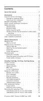 3
3 -
 4
4 -
 5
5 -
 6
6 -
 7
7 -
8
-
9
-
10
-
11
-
12
-
13
-
14
-
15
-
16
-
17
-
18
-
19
-
20
-
21
-
22
-
23
-
24
-
25
-
26
-
27
-
28
-
29
-
30
-
31
-
32
-
33
-
34
-
35
-
36
-
37
-
38
-
39
-
40
-
41
-
42
-
43
-
44
-
45
-
46
-
47
-
48
-
49
-
50
-
51
-
52
-
53
-
54
-
55
-
56
-
57
-
58
-
59
-
60
-
61
-
62
-
63
-
64
-
65
-
66
-
67
-
68
-
69
-
70
-
71
-
72
-
73
-
74
-
75
-
76
-
77
-
78
-
79
-
80
-
81
-
82
-
83
-
84
-
85
-
86
-
87
-
88
-
89
-
90
-
91
-
92
-
93
-
94
-
95
-
96
-
97
-
98
-
99
-
100
-
101
-
102
-
103
-
104
-
105
-
106
-
107
-
108
-
109
-
110
-
111
-
112
-
113
-
114
-
115
-
116
-
117
-
118
-
119
-
120
-
121
-
122
-
123
-
124
-
125
-
126
-
127
-
128
-
129
-
130
-
131
-
132
-
133
-
134
-
135
-
136
-
137
-
138
-
139
-
140
-
141
-
142
-
143
-
144
-
145
-
146
-
147
-
148
-
149
-
150
-
151
-
152
-
153
-
154
-
155
-
156
-
157
-
158
-
159
-
160
-
161
-
162
-
163
-
164
-
165
-
166
-
167
-
168
-
169
-
170
-
171
-
172
-
173
-
174
-
175
-
176
-
177
-
178
-
179
-
180
-
181
-
182
-
183
-
184
-
185
-
186
-
187
-
188
-
189
-
190
-
191
-
192
-
193
-
194
-
195
-
196
-
197
-
198
-
199
-
200
-
201
-
202
-
203
-
204
-
205
-
206
-
207
-
208
-
209
-
210
-
211
-
212
-
213
-
214
-
215
-
216
-
217
-
218
-
219
-
220
-
221
-
222
-
223
-
224
-
225
-
226
-
227
-
228
-
229
-
230
-
231
-
232
-
233
-
234
-
235
-
236
-
237
-
238
-
239
-
240
-
241
-
242
-
243
-
244
-
245
-
246
-
247
-
248
-
249
-
250
-
251
-
252
-
253
-
254
-
255
-
256
-
257
-
258
-
259
-
260
 |
 |

ThinkPad
Computer
Hardware
Maintenance
Manual
February 2006
This manual supports:
ThinkPad T40/T40p, T41/T41p, T42/T42p
ThinkPad
Dock II (MT 2877)
(MT 2373/2374/
/
)
2375 2376/2378/2379