IBM 84885BU User Manual - Page 127
Hot-swap, power-supply, errors
 |
View all IBM 84885BU manuals
Add to My Manuals
Save this manual to your list of manuals |
Page 127 highlights
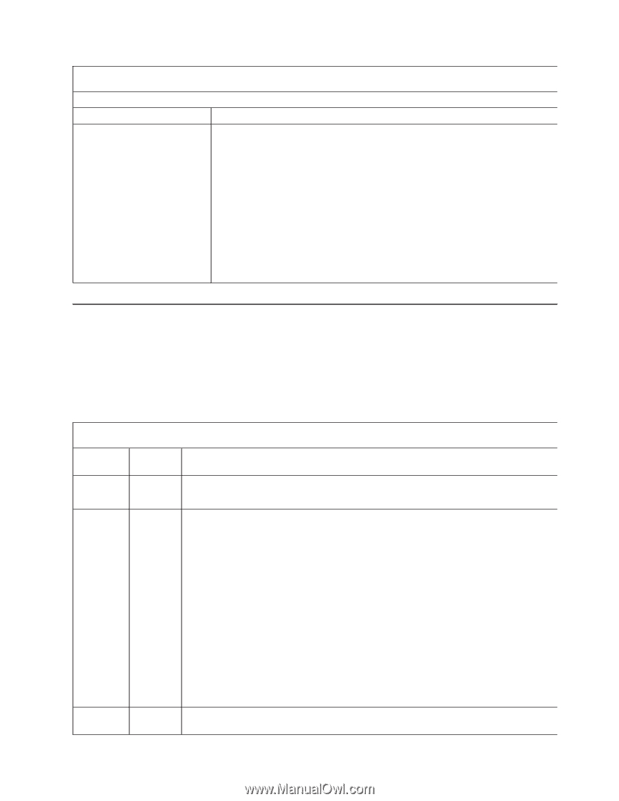
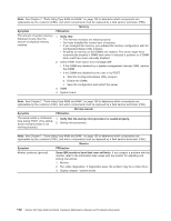
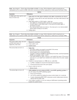
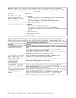
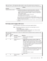
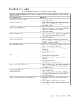
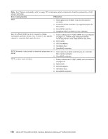
Note: See Chapter 7, "Parts listing Type 8488 and 8648," on page 129 to determine which components are replaceable by the customer (CRU), and which components must be replaced by a field service technician (FRU). Software Symptom FRU/action Suspected software problem. 1. To determine if problems are caused by the software, verify that: v The server has the minimum memory needed to use the software. For memory requirements, see the information that comes with the software. Note: If you have just installed an adapter or memory, you might have a memory address conflict. v The software is designed to operate on the server. v Other software works on the server. v The software that you are using works on another system. If you received any error messages when using the software program, see the information that comes with the software for a description of the messages and suggested solutions to the problem. 2. If you have verified these items and the problem remains, contact the place of purchase. Hot-swap power-supply LED errors Use the information in this section to solve power-supply problems. Note: The minimum configuration required for the dc good light to be lit is: v Power supply v Power cage assembly, if installed. v System board (press the power-control button; see "Server controls, connectors, LEDs, and power" on page 4). Note: See "System replaceable units" on page 131 to determine which components should be replaced by a field service technician. AC good LED DC good LED Description FRU/action Off Off No power to system or 1. Check ac power to the system. ac problem. 2. Power supply. On Off Standby mode or dc 1. Check system board cable connectors JPWR1 and problem. JPWR2. (See "System board internal connectors" on page 86.) Press the power-control button; see "Server controls, connectors, LEDs, and power" on page 4. If the dc good LED is lit, press Ctrl+Alt+Delete. Watch the screen for any POST errors. Check the system error log for any listed problems. If the system starts with no errors: a. Power switch assembly b. System board 2. Remove the adapters and disconnect the cables and power connectors to all internal and external devices. Turn on the system. If the dc good LED is lit, replace the adapters and devices one at a time until you isolate the problem. 3. Power supply. 4. Power cage assembly, if installed. 5. System board. On On Power is working N/A properly. Chapter 6. Symptom-to-FRU index 117
-
 1
1 -
2
-
3
-
4
-
5
-
6
-
7
-
8
-
9
-
10
-
11
-
12
-
13
-
14
-
15
-
16
-
17
-
18
-
19
-
20
-
21
-
22
-
23
-
24
-
25
-
26
-
27
-
28
-
29
-
30
-
31
-
32
-
33
-
34
-
35
-
36
-
37
-
38
-
39
-
40
-
41
-
42
-
43
-
44
-
45
-
46
-
47
-
48
-
49
-
50
-
51
-
52
-
53
-
54
-
55
-
56
-
57
-
58
-
59
-
60
-
61
-
62
-
63
-
64
-
65
-
66
-
67
-
68
-
69
-
70
-
71
-
72
-
73
-
74
-
75
-
76
-
77
-
78
-
79
-
80
-
81
-
82
-
83
-
84
-
85
-
86
-
87
-
88
-
89
-
90
-
91
-
92
-
93
-
94
-
95
-
96
-
97
-
98
-
99
-
100
-
101
-
102
-
103
-
104
-
105
-
106
-
107
-
108
-
109
-
110
-
111
-
112
-
113
-
114
-
115
-
116
-
117
-
118
-
119
-
120
-
121
-
 122
122 -
 123
123 -
 124
124 -
 125
125 -
 126
126 -
 127
127 -
 128
128 -
 129
129 -
 130
130 -
 131
131 -
 132
132 -
133
-
134
-
135
-
136
-
137
-
138
-
139
-
140
-
141
-
142
-
143
-
144
-
145
-
146
-
147
-
148
-
149
-
150
-
151
-
152
-
153
-
154
-
155
-
156
-
157
-
158
-
159
-
160
-
161
-
162
-
163
-
164
-
165
-
166
-
167
-
168
-
169
-
170
-
171
-
172
-
173
-
174
-
175
-
176
-
177
-
178
-
179
-
180
-
181
-
182
-
183
-
184
-
185
-
186
-
187
-
188
-
189
-
190
-
191
-
192
-
193
-
194
-
195
-
196
-
197
-
198
-
199
-
200
 |
 |