IBM 84885BU User Manual - Page 51
Attention
 |
View all IBM 84885BU manuals
Add to My Manuals
Save this manual to your list of manuals |
Page 51 highlights
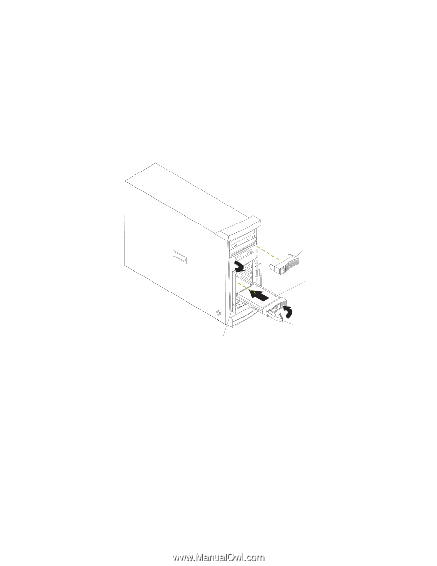
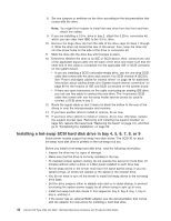
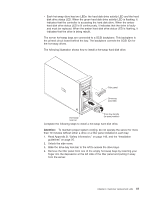
v Each hot-swap drive has two LEDs: the hard disk drive activity LED and the hard disk drive status LED. When the green hard disk drive activity LED is flashing, it indicates that the controller is accessing the hard disk drive. When the amber hard disk drive status LED is lit continuously, it indicates that the drive is faulty and must be replaced. When the amber hard disk drive status LED is flashing, it indicates that the drive is being rebuilt. The server hot-swap bays are connected to a SCSI backplane. This backplane is the printed circuit board behind the bay. The backplane controls the SCSI IDs for the hot-swap drives. The following illustration shows how to install a hot-swap hard disk drive. Filler panel Drive-tray assembly Hot-swap lock bar Drive tray-handle (in open position) Complete the following steps to install a hot-swap hard disk drive. Attention: To maintain proper system cooling, do not operate the server for more than 10 minutes without either a drive or a filler panel installed in each bay. 1. Read Appendix B, "Safety information," on page 143, and the "Installation guidelines" on page 25. 2. Unlock the side cover. 3. Slide the drive-bay lock bar to the left to access the drive bays. 4. Remove the filler panel from one of the empty hot-swap bays by inserting your finger into the depression at the left side of the filler panel and pulling it away from the server. Chapter 4. Customer replacement units 41
-
 1
1 -
2
-
3
-
4
-
5
-
6
-
7
-
8
-
9
-
10
-
11
-
12
-
13
-
14
-
15
-
16
-
17
-
18
-
19
-
20
-
21
-
22
-
23
-
24
-
25
-
26
-
27
-
28
-
29
-
30
-
31
-
32
-
33
-
34
-
35
-
36
-
37
-
38
-
39
-
40
-
41
-
42
-
43
-
44
-
45
-
 46
46 -
 47
47 -
 48
48 -
 49
49 -
 50
50 -
 51
51 -
 52
52 -
 53
53 -
 54
54 -
 55
55 -
 56
56 -
57
-
58
-
59
-
60
-
61
-
62
-
63
-
64
-
65
-
66
-
67
-
68
-
69
-
70
-
71
-
72
-
73
-
74
-
75
-
76
-
77
-
78
-
79
-
80
-
81
-
82
-
83
-
84
-
85
-
86
-
87
-
88
-
89
-
90
-
91
-
92
-
93
-
94
-
95
-
96
-
97
-
98
-
99
-
100
-
101
-
102
-
103
-
104
-
105
-
106
-
107
-
108
-
109
-
110
-
111
-
112
-
113
-
114
-
115
-
116
-
117
-
118
-
119
-
120
-
121
-
122
-
123
-
124
-
125
-
126
-
127
-
128
-
129
-
130
-
131
-
132
-
133
-
134
-
135
-
136
-
137
-
138
-
139
-
140
-
141
-
142
-
143
-
144
-
145
-
146
-
147
-
148
-
149
-
150
-
151
-
152
-
153
-
154
-
155
-
156
-
157
-
158
-
159
-
160
-
161
-
162
-
163
-
164
-
165
-
166
-
167
-
168
-
169
-
170
-
171
-
172
-
173
-
174
-
175
-
176
-
177
-
178
-
179
-
180
-
181
-
182
-
183
-
184
-
185
-
186
-
187
-
188
-
189
-
190
-
191
-
192
-
193
-
194
-
195
-
196
-
197
-
198
-
199
-
200
 |
 |