IBM 84885BU User Manual - Page 55
Installing, external, connector
 |
View all IBM 84885BU manuals
Add to My Manuals
Save this manual to your list of manuals |
Page 55 highlights
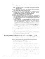
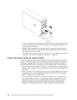
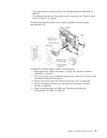
The following cables are provided: v Power cables: Four-wire power cables connect the drives to the power supply. At the end of these cables are plastic connectors that can be attached to different drives; these connectors vary in size. Use either a four-wire power cable or Serial ATA power cable with Serial ATA drives, but do not use both at the same time (use one or the other). For SCSI hot-swap drives, a special power cable connects the SCSI backplane to the power supply. v Signal cables: Signal cables are typically flat cables, also called ribbon cables, that connect parallel IDE, Serial ATA, SCSI, and diskette drives to the system board. Two or three types of signal cables come with the server: - IDE: The wider IDE signal cable has three connectors. One of these connectors is attached to the drive, one is a spare, and the third is attached to the primary IDE connector on the system board. The spare connector can be used to connect an additional IDE drive to the server. The CD-ROM drive is attached to an ATA 100 signal cable. ATA 100 signal cables are color-coded. The blue connector is attached to the system board. The black connector is attached to the master IDE device. The gray middle connector is attached to the subordinate IDE device. - Diskette drive: The narrower signal cable has two connectors. One is attached to the diskette drive, and the other is connected to the connector (FDD1) on the system board. - Serial ATA (SATA): The narrower, black signal cable has two connectors. One is connected to a simple-swap Serial ATA drive, and the other is attached to the connector on the system board. Each simple-swap Serial ATA drive comes with a cable. If you install an additional simple-swap Serial ATA drive, you will need an additional cable. If you install the optional ServeRAID-7t S-ATA controller to add a third and fourth SATA drive, all four SATA drives must then be connected to the ServeRAID-7t S-ATA controller instead of the system board. The optional ServeRAID-7t S-ATA controller comes with two cables that you can use to cable the third and fourth SATA drives. See the optional ServeRAID-7t S-ATA controller documentation for cabling instructions. - SCSI: A round SCSI cable connects the SCSI backplane to the SCSI channel B connector on the system board. The maximum cable length that supports Ultra320 SCSI hard disk drives is 61 cm (24 in.). Installing an external SCSI connector To install an external SCSI connector on the rear of the server, install an external SCSI interface option. For a list of supported external SCSI interface options for the server, go to http://www.ibm.com/pc/compat/. The external SCSI interface option contains a SCSI cable with a connector at one end and another connector on the other end. Complete the following steps to install and route the SCSI cable in the server: 1. Turn off the server and all peripheral devices. Disconnect all power cords; then, disconnect all external signal cables from the server. 2. Remove the server cover (see "Removing the side cover" on page 28). 3. Remove the support bracket (see "Removing and installing the support bracket" on page 32). Chapter 4. Customer replacement units 45
-
 1
1 -
2
-
3
-
4
-
5
-
6
-
7
-
8
-
9
-
10
-
11
-
12
-
13
-
14
-
15
-
16
-
17
-
18
-
19
-
20
-
21
-
22
-
23
-
24
-
25
-
26
-
27
-
28
-
29
-
30
-
31
-
32
-
33
-
34
-
35
-
36
-
37
-
38
-
39
-
40
-
41
-
42
-
43
-
44
-
45
-
46
-
47
-
48
-
49
-
 50
50 -
 51
51 -
 52
52 -
 53
53 -
 54
54 -
 55
55 -
 56
56 -
 57
57 -
 58
58 -
 59
59 -
 60
60 -
61
-
62
-
63
-
64
-
65
-
66
-
67
-
68
-
69
-
70
-
71
-
72
-
73
-
74
-
75
-
76
-
77
-
78
-
79
-
80
-
81
-
82
-
83
-
84
-
85
-
86
-
87
-
88
-
89
-
90
-
91
-
92
-
93
-
94
-
95
-
96
-
97
-
98
-
99
-
100
-
101
-
102
-
103
-
104
-
105
-
106
-
107
-
108
-
109
-
110
-
111
-
112
-
113
-
114
-
115
-
116
-
117
-
118
-
119
-
120
-
121
-
122
-
123
-
124
-
125
-
126
-
127
-
128
-
129
-
130
-
131
-
132
-
133
-
134
-
135
-
136
-
137
-
138
-
139
-
140
-
141
-
142
-
143
-
144
-
145
-
146
-
147
-
148
-
149
-
150
-
151
-
152
-
153
-
154
-
155
-
156
-
157
-
158
-
159
-
160
-
161
-
162
-
163
-
164
-
165
-
166
-
167
-
168
-
169
-
170
-
171
-
172
-
173
-
174
-
175
-
176
-
177
-
178
-
179
-
180
-
181
-
182
-
183
-
184
-
185
-
186
-
187
-
188
-
189
-
190
-
191
-
192
-
193
-
194
-
195
-
196
-
197
-
198
-
199
-
200
 |
 |