IBM 84885BU User Manual - Page 57
connectors
 |
View all IBM 84885BU manuals
Add to My Manuals
Save this manual to your list of manuals |
Page 57 highlights
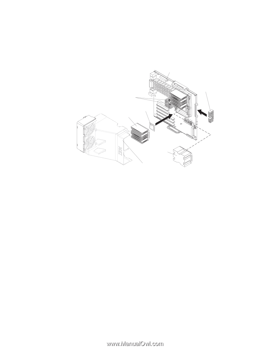
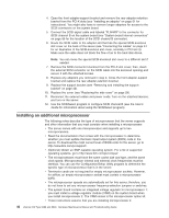
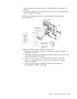
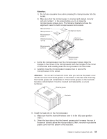
v If you must replace a microprocessor, see "Microprocessor and heat sink" on page 68. v For additional illustrations of the system-board components, see "System board option connectors" on page 85. The following illustration shows how to install an additional microprocessor (microprocessor 2). DIMMs Heat-sink release levers Microprocessor 2 Heat sink 2 VRM Microprocessor baffle assembly Microprocessor air baffle Complete the following steps to install a microprocessor: 1. Read Appendix B, "Safety information," on page 143, and the "Installation guidelines" on page 25. 2. Turn off the server and all peripheral devices; then, disconnect all power cords and external cables from the server. 3. Remove the server cover (see "Removing the side cover" on page 28). 4. Remove the support bracket (see "Removing and installing the support bracket" on page 32). 5. Open the microprocessor air baffle (see "Opening and closing the microprocessor air baffle" on page 33). Chapter 4. Customer replacement units 47
-
 1
1 -
2
-
3
-
4
-
5
-
6
-
7
-
8
-
9
-
10
-
11
-
12
-
13
-
14
-
15
-
16
-
17
-
18
-
19
-
20
-
21
-
22
-
23
-
24
-
25
-
26
-
27
-
28
-
29
-
30
-
31
-
32
-
33
-
34
-
35
-
36
-
37
-
38
-
39
-
40
-
41
-
42
-
43
-
44
-
45
-
46
-
47
-
48
-
49
-
50
-
51
-
 52
52 -
 53
53 -
 54
54 -
 55
55 -
 56
56 -
 57
57 -
 58
58 -
 59
59 -
 60
60 -
 61
61 -
 62
62 -
63
-
64
-
65
-
66
-
67
-
68
-
69
-
70
-
71
-
72
-
73
-
74
-
75
-
76
-
77
-
78
-
79
-
80
-
81
-
82
-
83
-
84
-
85
-
86
-
87
-
88
-
89
-
90
-
91
-
92
-
93
-
94
-
95
-
96
-
97
-
98
-
99
-
100
-
101
-
102
-
103
-
104
-
105
-
106
-
107
-
108
-
109
-
110
-
111
-
112
-
113
-
114
-
115
-
116
-
117
-
118
-
119
-
120
-
121
-
122
-
123
-
124
-
125
-
126
-
127
-
128
-
129
-
130
-
131
-
132
-
133
-
134
-
135
-
136
-
137
-
138
-
139
-
140
-
141
-
142
-
143
-
144
-
145
-
146
-
147
-
148
-
149
-
150
-
151
-
152
-
153
-
154
-
155
-
156
-
157
-
158
-
159
-
160
-
161
-
162
-
163
-
164
-
165
-
166
-
167
-
168
-
169
-
170
-
171
-
172
-
173
-
174
-
175
-
176
-
177
-
178
-
179
-
180
-
181
-
182
-
183
-
184
-
185
-
186
-
187
-
188
-
189
-
190
-
191
-
192
-
193
-
194
-
195
-
196
-
197
-
198
-
199
-
200
 |
 |