IBM 84885BU User Manual - Page 62
Notes
 |
View all IBM 84885BU manuals
Add to My Manuals
Save this manual to your list of manuals |
Page 62 highlights
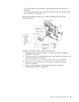
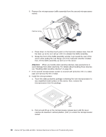
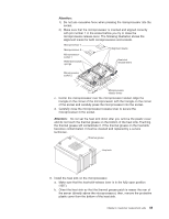
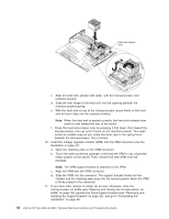
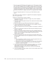
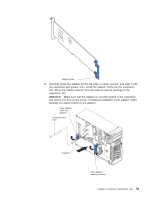
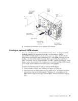
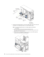
v The server scans the PCI Express x16 expansion slot 1, PCI expansion slots 2 and 3, and PCI-X expansion slots 4 through 6 to assign system resources. Then, the server starts the PCI devices in the following order, if you have not changed the default startup sequence: PCI Express x16 expansion slot 1; system-board integrated drive electronics (IDE), Serial ATA (SATA), or SCSI devices (including the optional ServeRAID 6i+ adapter); and then PCI-X expansion slots 4 through 6. v For a list of supported options for the server, go to http://www.ibm.com/pc/ support/. See "System board option connectors" on page 85 for the locations of expansion slots on the system board. Complete the following steps to install an adapter: 1. Read Appendix B, "Safety information," on page 143, and the "Installation guidelines" on page 25. 2. Turn off the server and peripheral devices; then, disconnect all external cables and power cords. 3. Remove the side cover (see "Removing the side cover" on page 28). 4. Follow the cabling instructions, if any, that come with the adapter. Route the adapter cables before you install the adapter. 5. Follow the instructions that come with the adapter to set jumpers or switches, if any. 6. Remove the frame-support bracket (see "Removing and installing the support bracket" on page 32). 7. Rotate the rear adapter-retention bracket to the open (unlocked) position and remove it from the server. Rotate the front adapter-support bracket to the open position. If you are installing a smaller adapter, remove only the rear adapter-retention bracket. 8. Remove the expansion-slot cover. From the rear of the server, press on the slot cover. Grasp it and pull it out of the expansion slot. Store it in a safe place for future use. Notes: a. If you are installing an adapter into slot 3, move the expansion-slot cover with the SCSI knockout to a vacant adapter slot. b. Expansion-slot covers must be installed on all vacant slots. This maintains the electronic emissions standards of the server and ensures proper ventilation of server components. 9. Touch the static-protective package containing the adapter to any unpainted metal surface on the server. Then, remove the adapter from the static-protective package. Avoid touching the components and gold-edge connectors on the adapter. 10. If you are installing a full-length adapter, remove the blue adapter guide (if any) from the end of the adapter. 52 xSeries 226 Type 8488 and 8648: Hardware Maintenance Manual and Troubleshooting Guide
-
 1
1 -
2
-
3
-
4
-
5
-
6
-
7
-
8
-
9
-
10
-
11
-
12
-
13
-
14
-
15
-
16
-
17
-
18
-
19
-
20
-
21
-
22
-
23
-
24
-
25
-
26
-
27
-
28
-
29
-
30
-
31
-
32
-
33
-
34
-
35
-
36
-
37
-
38
-
39
-
40
-
41
-
42
-
43
-
44
-
45
-
46
-
47
-
48
-
49
-
50
-
51
-
52
-
53
-
54
-
55
-
56
-
 57
57 -
 58
58 -
 59
59 -
 60
60 -
 61
61 -
 62
62 -
 63
63 -
 64
64 -
 65
65 -
 66
66 -
 67
67 -
68
-
69
-
70
-
71
-
72
-
73
-
74
-
75
-
76
-
77
-
78
-
79
-
80
-
81
-
82
-
83
-
84
-
85
-
86
-
87
-
88
-
89
-
90
-
91
-
92
-
93
-
94
-
95
-
96
-
97
-
98
-
99
-
100
-
101
-
102
-
103
-
104
-
105
-
106
-
107
-
108
-
109
-
110
-
111
-
112
-
113
-
114
-
115
-
116
-
117
-
118
-
119
-
120
-
121
-
122
-
123
-
124
-
125
-
126
-
127
-
128
-
129
-
130
-
131
-
132
-
133
-
134
-
135
-
136
-
137
-
138
-
139
-
140
-
141
-
142
-
143
-
144
-
145
-
146
-
147
-
148
-
149
-
150
-
151
-
152
-
153
-
154
-
155
-
156
-
157
-
158
-
159
-
160
-
161
-
162
-
163
-
164
-
165
-
166
-
167
-
168
-
169
-
170
-
171
-
172
-
173
-
174
-
175
-
176
-
177
-
178
-
179
-
180
-
181
-
182
-
183
-
184
-
185
-
186
-
187
-
188
-
189
-
190
-
191
-
192
-
193
-
194
-
195
-
196
-
197
-
198
-
199
-
200
 |
 |