IBM 84885BU User Manual - Page 67
Replacing, battery
 |
View all IBM 84885BU manuals
Add to My Manuals
Save this manual to your list of manuals |
Page 67 highlights
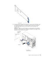
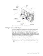
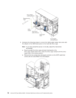
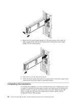
c. Thread the large connector into the small back-panel opening on the rear of a bay; then, orient the connector so that the blue signal cable is toward the front or outside of the server (see the preceding illustration) and gently pull the connector into place. d. Secure the connector with the two screws you removed in step 3b on page 56. e. Connect the power-cable drop to the connector. The connectors are keyed and can be inserted only one way. f. Repeat steps 3b on page 56 through 3e for the second SATA cable that comes with the ServeRAID-7t S-ATA adapter. g. Press in on the drive-cage release tab and rotate the drive cage partially back into the server. Press the drive-cage release latch and rotate the drive cage the rest of the way back into the server, allowing the release latch to spring back into position. h. Route the SATA cables through the upper slot in the front adapter-support-bracket assembly; then, connect the other end of the SATA cables to the ServeRAID-7t S-ATA adapter. 4. Complete the installation of the optional SATA adapter. Replacing the battery IBM has designed this product with your safety in mind. The lithium battery must be handled correctly to avoid possible danger. If you replace the battery, you must adhere to the following instructions. Note: In the U. S., call 1-800-IBM-4333 for information about battery disposal. If you replace the original lithium battery with a heavy-metal battery or a battery with heavy-metal components, be aware of the following environmental consideration. Batteries and accumulators that contain heavy metals must not be disposed of with normal domestic waste. They will be taken back free of charge by the manufacturer, distributor, or representative, to be recycled or disposed of in a proper manner. To order replacement batteries, call 1-800-426-7378 within the United States, and 1-800-465-7999 or 1-800-465-6666 within Canada. Outside the U.S. and Canada, call your IBM reseller or IBM marketing representative. Note: After you replace the battery, you must reconfigure the server and reset the system date and time. Chapter 4. Customer replacement units 57
-
 1
1 -
2
-
3
-
4
-
5
-
6
-
7
-
8
-
9
-
10
-
11
-
12
-
13
-
14
-
15
-
16
-
17
-
18
-
19
-
20
-
21
-
22
-
23
-
24
-
25
-
26
-
27
-
28
-
29
-
30
-
31
-
32
-
33
-
34
-
35
-
36
-
37
-
38
-
39
-
40
-
41
-
42
-
43
-
44
-
45
-
46
-
47
-
48
-
49
-
50
-
51
-
52
-
53
-
54
-
55
-
56
-
57
-
58
-
59
-
60
-
61
-
 62
62 -
 63
63 -
 64
64 -
 65
65 -
 66
66 -
 67
67 -
 68
68 -
 69
69 -
 70
70 -
 71
71 -
 72
72 -
73
-
74
-
75
-
76
-
77
-
78
-
79
-
80
-
81
-
82
-
83
-
84
-
85
-
86
-
87
-
88
-
89
-
90
-
91
-
92
-
93
-
94
-
95
-
96
-
97
-
98
-
99
-
100
-
101
-
102
-
103
-
104
-
105
-
106
-
107
-
108
-
109
-
110
-
111
-
112
-
113
-
114
-
115
-
116
-
117
-
118
-
119
-
120
-
121
-
122
-
123
-
124
-
125
-
126
-
127
-
128
-
129
-
130
-
131
-
132
-
133
-
134
-
135
-
136
-
137
-
138
-
139
-
140
-
141
-
142
-
143
-
144
-
145
-
146
-
147
-
148
-
149
-
150
-
151
-
152
-
153
-
154
-
155
-
156
-
157
-
158
-
159
-
160
-
161
-
162
-
163
-
164
-
165
-
166
-
167
-
168
-
169
-
170
-
171
-
172
-
173
-
174
-
175
-
176
-
177
-
178
-
179
-
180
-
181
-
182
-
183
-
184
-
185
-
186
-
187
-
188
-
189
-
190
-
191
-
192
-
193
-
194
-
195
-
196
-
197
-
198
-
199
-
200
 |
 |