IBM 84885BU User Manual - Page 76
Universal, Serial, connectors, Video, connector
 |
View all IBM 84885BU manuals
Add to My Manuals
Save this manual to your list of manuals |
Page 76 highlights
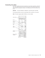
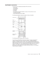
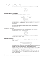
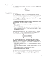
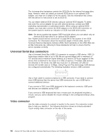
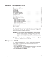
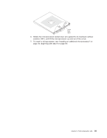
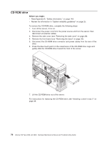
The hot-swap-drive backplane controls the SCSI IDs for the internal hot-swap drive bays. However, when you attach an external SCSI device to an optional SCSI adapter, you must set a unique ID for the device. See the information that comes with the device for instructions to set its SCSI ID. You can attach external SCSI devices using an optional SCSI adapter. To select and order the correct adapter for use with external devices, contact your IBM marketing representative or authorized reseller. When using an optional SCSI adapter, you must also connect the SCSI adapter to the SCSI LED connector on the system board to receive an indication of SCSI hard disk drive activity. Note: On server models that support SATA hard disk drives, you can attach only an external SCSI tape drive to an optional SCSI adapter. See "System board internal connectors" on page 86 for the location of the SCSI connectors. For information about the maximum length of SCSI cable, see the American National Standards Institute (ANSI) SCSI standards on the ANSI Web site at http://www.ansi.org/. Adhering to these standards will help to ensure that the server operates correctly. Universal Serial Bus connectors Use a Universal Serial Bus (USB) 2.0 connector to connect a USB device. USB 2.0 technology transfers data at up to 480 Mb per second (Mbps) with a maximum of 127 devices and a maximum signal distance of 5 meters (16 ft) per segment (if the device that is attached to the server is a USB 2.0 device). If multiple USB devices are attached to the server, the USB hub must be 2.0; otherwise, all USB 2.0 devices will transfer data at 12 Mbps. Using Plug and Play technology, USB devices are configured automatically. The following illustration shows a USB connector. 1 4 Use a 4-pin cable to connect a device to a USB connector. If you need to connect more USB devices than the server has USB connectors for, use a USB hub to connect additional devices. If you connect a PS/2 (non-USB) keyboard to the keyboard connector, USB ports and devices are disabled during POST. If you connect a USB keyboard that has a mouse port, the keyboard emulates a mouse, and you cannot disable the mouse settings in the Configuration/Setup Utility program. Video connector Use the video connector to connect a monitor to the server. The connector is dark blue to help you identify it. The following illustration shows an industry-standard 15-pin analog video connector on the rear of the server. 5 1 15 11 66 xSeries 226 Type 8488 and 8648: Hardware Maintenance Manual and Troubleshooting Guide
-
 1
1 -
2
-
3
-
4
-
5
-
6
-
7
-
8
-
9
-
10
-
11
-
12
-
13
-
14
-
15
-
16
-
17
-
18
-
19
-
20
-
21
-
22
-
23
-
24
-
25
-
26
-
27
-
28
-
29
-
30
-
31
-
32
-
33
-
34
-
35
-
36
-
37
-
38
-
39
-
40
-
41
-
42
-
43
-
44
-
45
-
46
-
47
-
48
-
49
-
50
-
51
-
52
-
53
-
54
-
55
-
56
-
57
-
58
-
59
-
60
-
61
-
62
-
63
-
64
-
65
-
66
-
67
-
68
-
69
-
70
-
 71
71 -
 72
72 -
 73
73 -
 74
74 -
 75
75 -
 76
76 -
 77
77 -
 78
78 -
 79
79 -
 80
80 -
 81
81 -
82
-
83
-
84
-
85
-
86
-
87
-
88
-
89
-
90
-
91
-
92
-
93
-
94
-
95
-
96
-
97
-
98
-
99
-
100
-
101
-
102
-
103
-
104
-
105
-
106
-
107
-
108
-
109
-
110
-
111
-
112
-
113
-
114
-
115
-
116
-
117
-
118
-
119
-
120
-
121
-
122
-
123
-
124
-
125
-
126
-
127
-
128
-
129
-
130
-
131
-
132
-
133
-
134
-
135
-
136
-
137
-
138
-
139
-
140
-
141
-
142
-
143
-
144
-
145
-
146
-
147
-
148
-
149
-
150
-
151
-
152
-
153
-
154
-
155
-
156
-
157
-
158
-
159
-
160
-
161
-
162
-
163
-
164
-
165
-
166
-
167
-
168
-
169
-
170
-
171
-
172
-
173
-
174
-
175
-
176
-
177
-
178
-
179
-
180
-
181
-
182
-
183
-
184
-
185
-
186
-
187
-
188
-
189
-
190
-
191
-
192
-
193
-
194
-
195
-
196
-
197
-
198
-
199
-
200
 |
 |