IBM 84885BU User Manual - Page 89
frame-support
 |
View all IBM 84885BU manuals
Add to My Manuals
Save this manual to your list of manuals |
Page 89 highlights
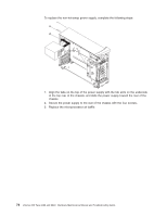
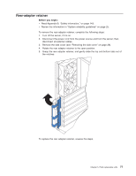
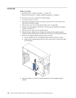
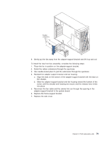
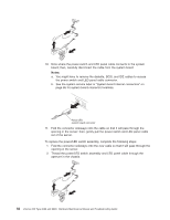
Rubber extensions 9. Gently pry the fan away from the adapter-support bracket and lift it up and out. To install the new front fan assembly, complete the following steps: 1. Place the fan in position on the adapter-support bracket. 2. Guide the rubber extensions through the apertures. 3. Use needle-nosed pliers to pull the extensions through the apertures. 4. Reinstall the adapter-support bracket and fan housing: a. Align the slots on the bottom of the adapter-support bracket with the tabs on the chassis. b. Slide the adapter-support bracket and fan housing toward the bottom of the server until the bracket and housing are secure and the release lever clicks into place. 5. Reconnect the fan cable and the cables that run through the opening in the adapter-support bracket to the system board. 6. Replace the frame-support bracket. 7. Replace the side cover. Chapter 5. Field replaceable units 79
-
 1
1 -
2
-
3
-
4
-
5
-
6
-
7
-
8
-
9
-
10
-
11
-
12
-
13
-
14
-
15
-
16
-
17
-
18
-
19
-
20
-
21
-
22
-
23
-
24
-
25
-
26
-
27
-
28
-
29
-
30
-
31
-
32
-
33
-
34
-
35
-
36
-
37
-
38
-
39
-
40
-
41
-
42
-
43
-
44
-
45
-
46
-
47
-
48
-
49
-
50
-
51
-
52
-
53
-
54
-
55
-
56
-
57
-
58
-
59
-
60
-
61
-
62
-
63
-
64
-
65
-
66
-
67
-
68
-
69
-
70
-
71
-
72
-
73
-
74
-
75
-
76
-
77
-
78
-
79
-
80
-
81
-
82
-
83
-
 84
84 -
 85
85 -
 86
86 -
 87
87 -
 88
88 -
 89
89 -
 90
90 -
 91
91 -
 92
92 -
 93
93 -
 94
94 -
95
-
96
-
97
-
98
-
99
-
100
-
101
-
102
-
103
-
104
-
105
-
106
-
107
-
108
-
109
-
110
-
111
-
112
-
113
-
114
-
115
-
116
-
117
-
118
-
119
-
120
-
121
-
122
-
123
-
124
-
125
-
126
-
127
-
128
-
129
-
130
-
131
-
132
-
133
-
134
-
135
-
136
-
137
-
138
-
139
-
140
-
141
-
142
-
143
-
144
-
145
-
146
-
147
-
148
-
149
-
150
-
151
-
152
-
153
-
154
-
155
-
156
-
157
-
158
-
159
-
160
-
161
-
162
-
163
-
164
-
165
-
166
-
167
-
168
-
169
-
170
-
171
-
172
-
173
-
174
-
175
-
176
-
177
-
178
-
179
-
180
-
181
-
182
-
183
-
184
-
185
-
186
-
187
-
188
-
189
-
190
-
191
-
192
-
193
-
194
-
195
-
196
-
197
-
198
-
199
-
200
 |
 |
