IBM 84885BU User Manual - Page 92
locations.
 |
View all IBM 84885BU manuals
Add to My Manuals
Save this manual to your list of manuals |
Page 92 highlights
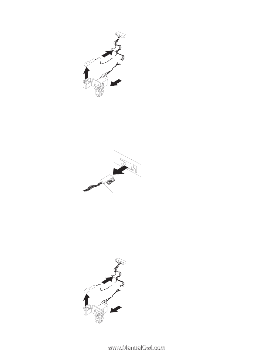
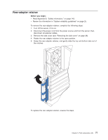
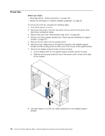
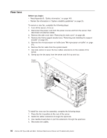
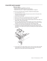
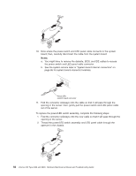
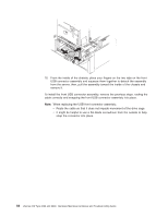
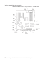
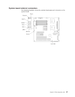
10. Note where the power-switch and LED panel cable connects to the system board; then, carefully disconnect the cable from the system board. Notes: a. You might have to remove the diskette, SCSI, and IDE cables to access the power switch and LED panel cable connector. b. See the system service label or "System board internal connectors" on page 86 for system board connector locations. Power/LED system board connector 11. Fold the connector sideways onto the cable so that it will pass through the opening in the server; then, gently pull the power-switch and LED panel cable out of the server. To replace the power/LED switch assembly, complete the following steps: 1. Fold the connector sideways onto the new cable so that it will pass through the opening in the server. 2. Thread the power/LED switch assembly and LED panel cable through the aperture in the chassis. 82 xSeries 226 Type 8488 and 8648: Hardware Maintenance Manual and Troubleshooting Guide
-
 1
1 -
2
-
3
-
4
-
5
-
6
-
7
-
8
-
9
-
10
-
11
-
12
-
13
-
14
-
15
-
16
-
17
-
18
-
19
-
20
-
21
-
22
-
23
-
24
-
25
-
26
-
27
-
28
-
29
-
30
-
31
-
32
-
33
-
34
-
35
-
36
-
37
-
38
-
39
-
40
-
41
-
42
-
43
-
44
-
45
-
46
-
47
-
48
-
49
-
50
-
51
-
52
-
53
-
54
-
55
-
56
-
57
-
58
-
59
-
60
-
61
-
62
-
63
-
64
-
65
-
66
-
67
-
68
-
69
-
70
-
71
-
72
-
73
-
74
-
75
-
76
-
77
-
78
-
79
-
80
-
81
-
82
-
83
-
84
-
85
-
86
-
 87
87 -
 88
88 -
 89
89 -
 90
90 -
 91
91 -
 92
92 -
 93
93 -
 94
94 -
 95
95 -
 96
96 -
 97
97 -
98
-
99
-
100
-
101
-
102
-
103
-
104
-
105
-
106
-
107
-
108
-
109
-
110
-
111
-
112
-
113
-
114
-
115
-
116
-
117
-
118
-
119
-
120
-
121
-
122
-
123
-
124
-
125
-
126
-
127
-
128
-
129
-
130
-
131
-
132
-
133
-
134
-
135
-
136
-
137
-
138
-
139
-
140
-
141
-
142
-
143
-
144
-
145
-
146
-
147
-
148
-
149
-
150
-
151
-
152
-
153
-
154
-
155
-
156
-
157
-
158
-
159
-
160
-
161
-
162
-
163
-
164
-
165
-
166
-
167
-
168
-
169
-
170
-
171
-
172
-
173
-
174
-
175
-
176
-
177
-
178
-
179
-
180
-
181
-
182
-
183
-
184
-
185
-
186
-
187
-
188
-
189
-
190
-
191
-
192
-
193
-
194
-
195
-
196
-
197
-
198
-
199
-
200
 |
 |