IBM 8837 User Guide - Page 22
connector, Power, Power-control, button, drive, activity, Location, Information, System-error,
 |
UPC - 000435421401
View all IBM 8837 manuals
Add to My Manuals
Save this manual to your list of manuals |
Page 22 highlights
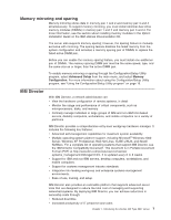
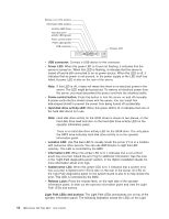
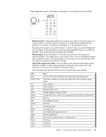
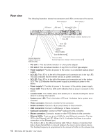
System-error LED (amber) Information LED (amber) Location LED (blue) Hard disk drive activity LED (green) Power control button Power LED (green) USB connector Release latch v USB connector: Connect a USB device to this connector. v Power LED: When this green LED is lit and not flashing, it indicates that the server is turned on. When this LED is flashing, it indicates that the server is turned off and is still connected to an ac power source. When this LED is off, it indicates that ac power is not present, or the power supply or the LED itself has failed. A power LED is also on the rear of the server. Note: If this LED is off, it does not mean that there is no electrical power in the server. The LED might be burned out. To remove all electrical power from the server, you must disconnect the power cord from the electrical outlet. v Power-control button: Press this button to turn the server on and off manually. A power-control-button shield comes with the server. You can install this disk-shaped shield to prevent the server from being turned off accidentally. v Hard disk drive activity LED: When this green LED is lit, it indicates that one of the hard disk drives is in use. Note: Hard disk drive activity for the SCSI drives is shown in two places, on the hard disk drive itself and also on the hard disk drive activity LED on the operator information panel. There is no hard disk drive activity LED for the SATA drive. The only place the SATA drive indicates hard disk drive activity is on the operator information panel. v Location LED: Use this blue LED to visually locate the server if it is in a location with numerous other servers. You can use IBM Director to light this LED remotely. This LED is controlled by the BMC. v Information LED: When this amber LED is lit, it indicates that a non-critical event has occurred. Check the error log for additional information. See the note in the "Light Path diagnostics panel" section, in the Option Installation Guide, for more information about error logs. v System-error LED: When this amber LED is lit, it indicates that a system error has occurred. A System-error LED is also on the rear of the server. An LED on the Light Path diagnostics panel on the system board is also lit to help isolate the error. This LED is controlled by the BMC. v Release Latch: Press the release latch, on the right side of the operator information panel, to slide out the operator information panel and view the Light Path LEDs and buttons. Light Path LEDs and buttons: The Light Path LEDs and buttons are on top of the operator information panel. The following illustration shows the LEDs on the Light 10 IBM xSeries 336 Type 8837: User's Guide
-
 1
1 -
2
-
3
-
4
-
5
-
6
-
7
-
8
-
9
-
10
-
11
-
12
-
13
-
14
-
15
-
16
-
 17
17 -
 18
18 -
 19
19 -
 20
20 -
 21
21 -
 22
22 -
 23
23 -
 24
24 -
 25
25 -
 26
26 -
 27
27 -
28
-
29
-
30
-
31
-
32
-
33
-
34
-
35
-
36
-
37
-
38
-
39
-
40
-
41
-
42
-
43
-
44
-
45
-
46
-
47
-
48
-
49
-
50
-
51
-
52
-
53
-
54
-
55
-
56
-
57
-
58
-
59
-
60
-
61
-
62
-
63
-
64
-
65
-
66
-
67
-
68
-
69
-
70
 |
 |