Icom IC-FR5000 Trunking/network Controller
Icom IC-FR5000 Manual
 |
View all Icom IC-FR5000 manuals
Add to My Manuals
Save this manual to your list of manuals |
Icom IC-FR5000 manual content summary:
- Icom IC-FR5000 | Trunking/network Controller - Page 1
slightly differs, depending on the Operating System version. INSTRUCTIONS TRUNKING/NETWORK CONTROLLER UC-FR5000 Thank you for choosing this Icom product. The controller is designed to be installed into the ICFR5000/IC-FR6000 series vhf /uhf fm repeaters and enables the on-line control and digital - Icom IC-FR5000 | Trunking/network Controller - Page 2
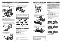
as that supplied with UC-FR5000 #03. Rear Bottom Icom, Icom Inc. and the Icom logo are registered trademarks of Icom Incorporated (Japan) in Japan, their original positions, and then connect the control cable of the repeater's front panel to the channel module. Channel module Control cable
-
 1
1 -
 2
2
 |
 |

INSTRUCTIONS
A-6691H-1EX-
u
Printed in Japan
© 2008–2016
Icom Inc.
1-1-32 Kamiminami, Hirano-ku, Osaka 547-0003, Japan
TRUNKING/NETWORK CONTROLLER
UC-FR5000
- 4 -
Thank you for choosing this Icom product.
The controller is designed to be installed into the IC-
FR5000/IC-FR6000 series
VHF
/
UHF
FM
REPEATERS
and
enables the on-line control and digital trunking operation
on the repeater.
READ ALL INSTRUCTIONS
carefully and completely
before using this product.
- 1 -
1.
Unscrew the seven screws from the top, and the two
screws on both sides of the repeater, then slide the top
cover off in the direction of the arrow.
P
0
P
1
P
2
P
3
P
4
Top cover
Repeater
2.
Disconnect the control cable from the channel module.
Then, unscrew the seven screws that affix the channel
module to the repeater chassis, and then remove it.
P
0
P
1
P
2
P
3
P
4
Control cable
Channel module
Front panel*
Repeater
* The front panel is removed in this illustration so the details are
easier to see. However, you can remove the channel module
without removing the front panel of the repeater.
3.
Unscrew the eight screws from the top, the nine screws
from bottom, and the three screws from rear of the
channel module. Then remove each cover from it.
Channel module
R
WARNING!
Turn OFF the repeater before installing the
controller. Otherwise a fire, electric shock may occur, or the
repeater could malfunction.
CAUTION: NEVER
expose the repeater or controller to
rain, snow or any liquids.
CAUTION: NEVER
let metal, wire or other objects touch
any internal part of the controller.
CAUTION:
Install the controller in only the specified repeater.
BE CAREFUL!
When you install the controller, wear gloves
to avoid cutting your hand on the sharp edges of the repeater.
PRECAUTIONS
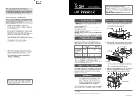
The controller enables the repeater to be used for the
following modes, depending on the configurations. (This
table is shown in controllers whose revision number is 3.5
or later. Ask your dealer for details.)
Single Site
Multi Site
Conventional
Trunking
Conventional
Trunking
UC-FR5000#01
✔
*
1
✔
✔
*
2
✔
*
3
UC-FR5000#02
(CF-FR5000MC is
supplied)
✔
✔
✔
✔
*
3
UC-FR5000#03
(CF-FR5000MT is
supplied)
✔
✔
✔
✔
UC-FR5000#04
✔
*
1
✔
✔
*
2
✔
*
3
*
1
When the optional RS-FS10 remote communicator is used, ei-
ther the CF-FR5000MC or CF-FR5000MT is required.
*
2
Either the optional CF-FR5000MC or CF-FR5000MT is required.
*
3
The optional CF-FR5000MT is required.
CONFIGURATIONS
The supplied or optional CF card must be inserted to enable
the Multi Site Conventional or Trunking mode use. Before
inserting a CF card to the controller’s card slot, carefully
read the card’s instructions.
ABOUT THE CF CARD
DISPOSAL
DISASSEMBLING THE UNITS
The crossed-out wheeled-bin symbol on your
product, literature, or packaging reminds you
that in the European Union, all electrical and
electronic products, batteries, and accumulators
(rechargeable batteries) must be taken to
designated collection locations at the end of their working
life. Do not dispose of these products as unsorted municipal
waste. Dispose of them according to the laws in your area.
NOTE:
Internet Explorer 6.0 or later is required to
correctly open the setting screen of the controller. The
following instructions are based on using Internet Explorer
7.0. JavaScript must be installed to open the side menu
and help window of the Setting screen.
D
Accessing the setting screen
NOTE:
You must wait to launch the web browser until the
controller system software startup is completed.It typically
takes 2 ~ 3 minutes for the controller to
startup the application.
1.
Connect a CAT-5 straight cable between the
controller’s [LAN] connector and a PC (p. 3) and then
turn ON the repeater.
2.
Before accessing the Setting screen, change the IP
address of the PC to 192.168.0.XXX* (A subnet mask
should be 255.255.255.0) in the Control Panel.
*
Replace XXX with any number between 1 and 254 (except 11).
L
Refer to the Operating System’s manual for details.
3.
Open your web browser, enter “http:// 192.168.0.11/”
(default IP address of the UC-FR5000) into the address
bar, and then push [Enter].
•
The Login Authentication screen is displayed.
L
Ask your system administrator for details.
4.
Enter “cbadmin” (default user name) and “ucfr5000”
(default password) in their respective input field in the
Login Authentication screen, and then click <OK>.
If you want the screen to remember not only the
user name but also the password, check the box,
“Remember my password”.
•
The Opening screen is displayed.
TIP:
You can change the user name and password
in the Setting screen. Refer the help window of the
Setting screen for details.
Enter
Enter
Check
Click
THE SETTING SCREEN OF THE UC-FR5000
D
Opening the help window
The Setting screen of the controller has a help window to
describe functions and settings.
If you don’t understand the meaning of an item, or how to
configure the controller, click a question mark icon on the
screen to open the help window.
Click to open the help window for
“General Settings,” for example.
D
Initialization
You can reset all set contents, including the network settings
of the controller, to the factory default from the PC.
1.
Connect the controller to the PC, and then turn ON the
repeater.
2.
Open your web browser, enter the initialize address into
the address bar, and then push [Enter].
•
The initialize screen is displayed.
L
Initialize address:
http://(IP address):8080/init.html
L
When the IP address of the controller is 192.168.0.11*, enter
“http://192.168.0.11:8080/init.html” as the initialize address.
* The IP address is an example only. Check the IP address
of the controller.
3.
After checking the box “Yes, I agree,” click <RESET>
to initialize the settings.
TIP:
If you use the UC-FR5000 #03, you can
select whether or not to reset the Network settings
as well as other settings. Refer to the help window
for details.
L
This screen slightly differs, depending on the Operating
System version.
Enter
Check
Click