Icom IC-R9500 Instruction Manual
Icom IC-R9500 Manual
 |
View all Icom IC-R9500 manuals
Add to My Manuals
Save this manual to your list of manuals |
Icom IC-R9500 manual content summary:
- Icom IC-R9500 | Instruction Manual - Page 1
COMMUNICATIONS RECEIVER iR9500 Instruction Manual A-6553H-1EX-q Printed in Japan © 2007 Icom Inc. - Icom IC-R9500 | Instruction Manual - Page 2
you agree with Icom's philosophy of "technology first." Many hours of research and development went into the design of your IC-R9500. D FEATURES ❍ Ultimate receiver performance: 109 dB wide dynamic range and third-order intercept (IP3) of +40 dBm (HF bands only) ❍ 7-inch wide color TFT LCD ❍ Built - Icom IC-R9500 | Instruction Manual - Page 3
receiver. DO NOT use chemical agents such as benzine or al- cohol when cleaning the IC-R9500, as they can damage the receiver's surfaces. AVOID using or storing the receiver This voice coding Technology is licensed solely for use within this communications equipment. The user of this technology is - Icom IC-R9500 | Instruction Manual - Page 4
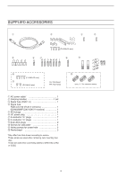
for side plate 4 !1 Hiding screws for screw hole 2 !2 Ferrite bead 3 *May differ from that shown according to version. †These screw are used when removing rack mounting han- dles. ‡These are used when connecting cables to [DATA IN], [LAN] or [USB]. !2 (see p. 2-7 for installation details) iii - Icom IC-R9500 | Instruction Manual - Page 5
adjustment 3-8 ■ Audio tone adjustment 3-9 D Treble level adjustment 3-9 D Bass level adjustment 3-9 ■ Meter indication selection 3-10 D Meter type selection 3-10 RECEIVE MODES ■ Operating FM 4-2 D Convenient functions for FM 4-2 ■ Duplex operation 4-3 D Offset frequency setting 4-3 iv - Icom IC-R9500 | Instruction Manual - Page 6
USA versions 4-20 D Convenient functions for TV operation 4-20 RECEIVE FUNCTIONS ■ Spectrum scope screen 5-2 D Center mode 5-2 D Fix mode 5-3 D Peak marker function 5-4 D Wide band-pass filter selection 5-5 D Wide band scope function 5-5 D Mini scope screen indication 5-6 D Scope set mode - Icom IC-R9500 | Instruction Manual - Page 7
RECORDER FUNCTIONS ■ About digital voice recorder 6-2 ■ Recording a received audio 6-3 D Regular recording 6-3 ■ Playing the recorded audio Memory channels 7-2 ■ Memory channel selection 7-3 D Using the [M-CH]/[BANK] selectors 7-3 D Using the keypad 7-3 ■ Memory channel programming 7-4 - Icom IC-R9500 | Instruction Manual - Page 8
11-22 ■ Formatting the CF card or USB-Memory 11-23 ■ Display set (Video) mode 11-24 ■ LCD set mode 11-26 Section 12 MAINTENANCE ■ Troubleshooting 12-2 D Receiver power 12-2 D Receiving 12-2 vii - Icom IC-R9500 | Instruction Manual - Page 9
D Data mode with filter width setting 13-11 Section 14 SPECIFICATIONS AND OPTIONS ■ Specifications 14-2 D General 14-2 D Receiver 14-3 ■ Options 14-4 Section 15 UPDATING THE FIRMWARE ■ General 15-2 ■ Caution 15-2 ■ Preparation 15-3 D Firmware and firm utility 15-3 D File downloading 15 - Icom IC-R9500 | Instruction Manual - Page 10
- Icom IC-R9500 | Instruction Manual - Page 11
PANEL DESCRIPTION Section 1 ■ Front panel 1-2 ■ Rear panel 1-10 ■ LCD display 1-12 ■ Screen menu arrangement 1-14 1-1 - Icom IC-R9500 | Instruction Manual - Page 12
Push for 1 sec. to turn the receiver power OFF. • The [POWER] indicator lights orange when the receiver is OFF when the internal power supply is The [PANEL LOCK] indicator above this switch lights green when the panel lock is in use. • The dial lock function is also available. ➥ Push and hold for 1 - Icom IC-R9500 | Instruction Manual - Page 13
AGC circuit time constant. • To use [AGC] control, push the appropriate band's [AGC VR/OFF] ([AGC VR " appear when manual notch is in use. ➥ Switches the manual notch characteristics between wide, middle and passband width to reject interference. This receiver uses the DSP circuit for the PBT - Icom IC-R9500 | Instruction Manual - Page 14
noise blanker 1, 2, or OFF when pushed. The noise blanker reduces pulse-type noise such as that generated by automobile ignition systems. This function cannot be used for FM, WFM, P25 modes or non-pulse-type noise. • The [NB] indicator above this switch lights green and " NB1 " or " NB2 " appears on - Icom IC-R9500 | Instruction Manual - Page 15
9-3) ➥ Selects one of 2 receive RF preamps or bypasses them. (p. 5-9) ● HF bands • "P. AMP1" activates 10 dB preamp. • "P. AMP2" activates high-gain preamp. ● Above 30 MHz bands • Only "P. AMP" is available to switch the voice squelch control function ON and OFF; useful for scanning. (p. 8-3) 1-5 - Icom IC-R9500 | Instruction Manual - Page 16
channel. ➥ Memory bank limit function ON or OFF when pushed and held for 1 sec. #1 REMOTE CONTROL INDICATOR [REMOTE] Lights yellow when a command is received from a PC via CI-V data. • When this indicator lights yellow, all dials, keys or switches other than [LOCAL] are disabled. • This indicator - Icom IC-R9500 | Instruction Manual - Page 17
or OFF in FM or WFM modes. • " AFC " appears when AFC function is in use. ➥ Turns the automatic tuning function ON or OFF in AM, SSB and CW modes. • IMPORTANT! When receiving a weak signal, or receiving a signal with interference, the automatic tuning function may tune the receiver to an undesired - Icom IC-R9500 | Instruction Manual - Page 18
1 sec. to enter the offset frequency set mode. $8 VOICE MEMORY RECORD SWITCH [REC] ➥ Short recording; Push momentarily to record the signal received for the preset time period before [REC] was pushed. (p.6-5) • Starts recording again automatically. ➥ Regular recording; Push and hold for 1 sec. to - Icom IC-R9500 | Instruction Manual - Page 19
MONITOR SWITCH [MONI] (pgs. 3-8, 4-4, 4-19) ➥ Push and hold to open the squelch manually. • The [MONI] indicator appears on the display. • While pushing and holding this switch, release any other receiving functions such as the noise blanker or ANF. • While in a duplex operation, monitor the shifted - Icom IC-R9500 | Instruction Manual - Page 20
external equipment such as an automatic antenna selector, a TNC for data communications, etc. • See p. 2-12 for socket information. r ANTENNA SELECTOR OUTPUT JACK [VIDEO OUT] Outputs video signals when TV frequencies with WFM mode are received. The NTSC M, PAL B/G, PAL I, PAL D and SECAM K system can - Icom IC-R9500 | Instruction Manual - Page 21
of the IC-R9500 without the optional CT-17, or the FSK decoded signal output. The [RS-232C] interface is wired as a modem (DCE). @8 CI-V REMOTE CONTROL JACK [REMOTE] (p. 2-6) ➥ Connects a PC via the optional CT-17 CI-V LEVEL CONVERTER for external control of the receiver. ➥ Used for transceive - Icom IC-R9500 | Instruction Manual - Page 22
FM, WFM or FSK modes. • FM/WFM modes • FSK mode • dBµ meter • dBµ (EMF) meter • dBm meter e MODE INDICATOR (p. 3-7) Shows the selected receive mode. r VFO/MEMORY INDICATOR (pgs. 3-3, 7-3) Indicates the selected VFO number (VFO-0 to VFO9) or memory mode. t IF FILTER INDICATOR (p. 5-12) Shows the - Icom IC-R9500 | Instruction Manual - Page 23
of the multifunction switches. !0 LCD FUNCTION SWITCH GUIDE Indicates the function of the LCD function switches MN1 " or " MN2 " appears when the manual notch filter function is in use. This function is available in AM, SSB, CW and FSK mode. @8 BAND WIDTH INDICATOR (p. 5-11) Shows the passband width - Icom IC-R9500 | Instruction Manual - Page 24
1 PANEL DESCRIPTION ■ Screen menu arrangement The following screens can be selected from the start up screen. Choose the desired screen using the following chart. Pushing [EXIT/SET] several times returns to the start up screen. See p. 11-3 for set mode arrangement. • Spectrum scope screen (p. - Icom IC-R9500 | Instruction Manual - Page 25
recording audio and frequency 2-9 ■ Monitor display connection 2-10 ■ Transceive function 2-10 ■ FSK and AFSK (SSTV) connections 2-11 ■ Accessory connector information 2-12 CAUTION!: The receiver weighs approx. 20 kg (44 lb). Always have two people available to carry, lift or turn over the - Icom IC-R9500 | Instruction Manual - Page 26
equipment included with the IC-R9500, see 'Supplied accessories' on p. iii of this manual. Select a location for the receiver that allows adequate air interference (TVI), broadcast interference (BCI) and other problems, ground the receiver through the GROUND terminal on the rear panel. For - Icom IC-R9500 | Instruction Manual - Page 27
receiver cannot give you the best performance. The IC-R9500 requires at least 2 antennas (ANT 1/HF ANT 3, ANT 2) for full coverage from 100 kHz to 3335 MHz. Select an antenna, such as a well matched 50 Ω antenna and feedline. When you wish to use a long wire antenna for short wave bands, use one - Icom IC-R9500 | Instruction Manual - Page 28
×16 mm FH: Flat head ■ Rack mounting handle detachment When removing the rack mounting handles, use the supplied screws for attach the side plates. q Remove the 6 screws from the rack mounting screw holes. If long screw is used, it is caused to damage the receiver's inside board. PH M4×8 mm 2-4 - Icom IC-R9500 | Instruction Manual - Page 29
signals come out from [VIDEO OUT] for USA versions. Ground (p. 2-2) Ground connection AC outlet R WARNING: Use the supplied AC power cable only. Antenna 1, 2 (p. 2-3) Connects the VHF, UHF wide band antennas. ANT1: 30-1150 MHz, ANT2: 1150-3335 MHz HF Antenna 1, 2, 3 (p. 2-3) [Example]: HF ANT1 - Icom IC-R9500 | Instruction Manual - Page 30
.5-15 V at least 10 A). Only regulated DC power may be connected. DATA socket (pgs.2-12) Antenna 1, 2 Connects a pre-amplifier, converter, etc. [REMOTE], [RS-232C] (p. 13-2) Used for computer control and transceive operation. The optional CT-17 is required when connecting a PC to [REMOTE]. 2-6 - Icom IC-R9500 | Instruction Manual - Page 31
signal data (48 kHz, 16bit) output. [USB] Connects a USB equipment such as memory, hub or keyboard. Ethernet connector (p. 15-6) Connects a PC via a LAN for CPU firmware update. For Ferrite bead installation (example: LAN cable) LAN socket 2-7 - Icom IC-R9500 | Instruction Manual - Page 32
. D Recording from the front panel or rear panel The [REC REMOTE] jack is grounded when a signal is received and squelch opens. If a tape recorder has a control terminal, this jack can be used for recording control. (2 A/DC max.) The [REC OUT] or [LINE OUT] jack has 350 mV rms/4.7 kΩ output - Icom IC-R9500 | Instruction Manual - Page 33
2 INSTALLATION AND CONNECTIONS D Separately recording audio and frequency When using a stereo tape recorder for recording, received audio and a frequency with a synthesized voice can be separately recorded. When recording this way, you can search ahead of the audio signal recorded in the - Icom IC-R9500 | Instruction Manual - Page 34
. TV set [VIDEO IN] or ■ Transceive function Icom CI-V transceivers or receivers can be connected via the [REMOTE] jack. The receivers, the connected radio's frequency/mode does not change. Connect [ACC] socket when the ICR9500 is connected with transceiver. This connection mutes the IC-R9500 - Icom IC-R9500 | Instruction Manual - Page 35
w Select FSK mode (or USB, CW modes for HF band data communications). e Set the receiver to the desired frequency as shown to the right. r Set the connected terminal unit to the appropriate settings. • Refer to the terminal unit's instructions. The narrow filter settings may not pass FSK signals. Be - Icom IC-R9500 | Instruction Manual - Page 36
signal output. (NTSC system only) 4 GND - 5 NC No connection 6 DATA - OUT 7, 8 NC No connection SPECIFICATIONS Output level : 1 V p-p ±0.2 V Output impedance : 75 Ω NOTE: If the beep level limit is in use, the beep tone decreases from the fixed level when the [AF] control is rotated above - Icom IC-R9500 | Instruction Manual - Page 37
BASIC OPERATIONS Section 3 ■ When first applying power (CPU resetting 3-2 ■ Initial settings 3-2 ■ Selecting VFO mode 3-3 ■ Selecting memory mode 3-3 ■ Frequency setting 3-4 D Direct frequency entry with the keypad 3-4 D Tuning with the main dial 3-5 D Selecting a tuning step 3-5 D Auto - Icom IC-R9500 | Instruction Manual - Page 38
) Before first applying power, make sure all connections required for your system are complete by referring to Section 2. Then, reset the receiver using the following procedure. Resetting CLEARS all programmed contents in memory channels and returns programmed values in set mode to default values - Icom IC-R9500 | Instruction Manual - Page 39
is commonly referred to as a main tuning function. Frequency, mode and other receiver settings are stored as a set of VFO data. The main dial is often called the "VFO knob." The IC-R9500 stores ten sets of VFO data. You can use the desired VFO to call up a frequency and operating mode for operation - Icom IC-R9500 | Instruction Manual - Page 40
ways to set a frequency: with the main dial or keypad. Use both in combination for quick tuning. • If the panel lock function function, push [LOCK]. D Direct frequency entry with the keypad Keypad [ENT] The receiver has a keypad for direct frequency entry as described below. q Input the desired - Icom IC-R9500 | Instruction Manual - Page 41
3 BASIC OPERATIONS D Tuning with the main dial [VFO] Number key TUNING STEP [DOWNZ]/[YUP] Main dial Rotate the main dial to change the frequency. • The frequency changes in increments determined by the selected tuning step (see below). q Push the desired VFO number (0 to 9) and [VFO]. • 10 - Icom IC-R9500 | Instruction Manual - Page 42
3 BASIC OPERATIONS • Setting the programmable tuning step Number key TUNING STEP [DOWNZ]/[YUP] D Auto tuning step function [F5•OTHERS] [F-7•SET] [F-1•Y] [F-2•Z] [EXIT/SET] q Push the numeral keys on the keypad that correspond to the tuning step you wish to program. • Programmable tuning steps can - Icom IC-R9500 | Instruction Manual - Page 43
-AM (S-AM(D)/SAM(U)/S-AM(L)), SSB (USB/LSB), CW, CW reverse (CW-R), FSK, FSK reverse (FSK-R) and DIGITAL (P25*) modes are available in the IC-R9500. Select the desired operation mode as follows. * P25 requires optional UT-122. To select a mode of operation, push the desired mode switch momentarily - Icom IC-R9500 | Instruction Manual - Page 44
(Recommended level; FM/AM mode only) The squelch disables output from the speaker (closed position) when no signal is received. ➥ When no signal is received, rotate [SQUELCH] control fully counterclockwise first, then rotate [SQUELCH] clockwise to the point that the noise just disappears. • Push - Icom IC-R9500 | Instruction Manual - Page 45
■ Audio tone adjustment D Treble level adjustment [TREBLE] Tone level decreases Tone level increases D Bass level adjustment [BASS] Tone level decreases Tone level increases 3 BASIC OPERATIONS NOTE: When [TREBLE] or [BASS] control is adjusted CCW, audio output decreases from [S/P DIF OUT], [ - Icom IC-R9500 | Instruction Manual - Page 46
selection D Meter type selection [F-3•DISPLAY] [F-7•SET] [F-1•Y] [F-2•Z] [EXIT/SET] A total of 4 meter types are available in the ICR9500- S-meter, dBµ, dBµ(EMF) and dBm meters. Follow the instructions below for the meter type selection. q Push [EXIT/SET] several times to return to normal screen - Icom IC-R9500 | Instruction Manual - Page 47
RECEIVE MODES Section 4 ■ Operating FM 4-2 D Convenient functions for FM 4-2 ■ Duplex operation 4-3 D Offset frequency setting 4-3 ■ Tone/DTCS squelch operation 4-4 ■ Operating WFM 4-5 D Convenient functions for WFM 4-5 ■ Operating AM 4-6 D - Icom IC-R9500 | Instruction Manual - Page 48
using the keypad. w Push [FM] to select FM. • " F M " indicator appears. e Rotate the main dial to tune the desired frequency. • [RX] indicator lights green and the S-meter indicates received signal strength when signal is received the attenuator in 6 dB steps for HF bands, or 10 dB step for 30-1150 - Icom IC-R9500 | Instruction Manual - Page 49
[FM] [DUP] [EXIT/SET] [MONI] Main dial Appears Duplex operation uses two different frequencies for transmitting and receiving. Generally, duplex is used in communication through a repeater, some utility communications, etc. During repeater operation, the transmit station frequency is shifted from - Icom IC-R9500 | Instruction Manual - Page 50
receiving a signal containing a matching subaudible tone or DTCS code. You can silently wait for calls from group members using the received signal's tone (or DTCS code) does not match, tone (DTCS) squelch does not open, however, the S-indicator shows signal strength. i To open the squelch manually - Icom IC-R9500 | Instruction Manual - Page 51
[RX] indicator Keypad [AF] [WFM] Appears Main dial 4 RECEIVE MODES q Edit the desired frequency using the keypad. w Push [WFM] to select WFM. • " ➥ Push [ATT] several times to set the attenuator in 6 dB steps for HF bands, or 10 dB step for 30-1150 MHz. Only 20 dB is available for 1150-3335 - Icom IC-R9500 | Instruction Manual - Page 52
using the keypad. w Push [AM] to select AM. • " A M " indicator appears. • After AM mode is selected, push and hold [AM] for 1 sec. to toggle between AM and S-AM modes. e Rotate the main dial to tune the desired frequency. • [RX] indicator lights green and the S-meter indicates received bands manual - Icom IC-R9500 | Instruction Manual - Page 53
Main dial Appears 4 RECEIVE MODES q Edit the desired frequency using the keypad. w Push times to set the attenuator in 6 dB steps for HF bands, or 10 dB step for 30-1150 MHz. Only 20 SLOW. ➥ Push [AGC VR] to turn the AGC time constant manual setting ON or OFF. • Rotate [AGC] control to adjust the - Icom IC-R9500 | Instruction Manual - Page 54
RECEIVE MODES ■ Operating CW [RX] indicator Keypad [AF] [SSB/CW] Main dial Appears q Edit the desired frequency using set the attenuator in 6 dB steps for HF bands, or 10 dB step for 30-1150 MHz. ➥ Push [AGC VR] to turn the AGC time constant manual setting ON or OFF. • Rotate [AGC] control to - Icom IC-R9500 | Instruction Manual - Page 55
(LSB side) BFO Interference Desired signal CW-R mode (USB side) CW-R (CW Reverse) mode uses the opposite side band to receive CW signals. Use when interfering signals are near a desired signal and you want to use CW-R to reduce the interference. ➥ During CW mode, push and hold [SSB/CW] for 1 sec - Icom IC-R9500 | Instruction Manual - Page 56
4 RECEIVE MODES ■ Operating FSK [RX] indicator Keypad [F-3•DECODE] [FSK] Appears Main dial A DSP-based high-quality Baudot FSK decoder is builtin to the IC-R9500. If you would rather use your FSK terminal or TNC, consult the manual that comes with the FSK terminal or TNC. q Edit the desired - Icom IC-R9500 | Instruction Manual - Page 57
to set the attenuator in 6 dB steps for HF bands, or 10 dB step for 30-1150 MHz. Only 20 above [NOTCH1] or [NOTCH2] switch) lights when either the manual notch is ON. • AGC (auto gain control) (p. 5-10 use. NOTE: When the twin peak filter is in use, the received audio output may increase. This is - Icom IC-R9500 | Instruction Manual - Page 58
MODES D Setting FSK tone frequency FSK RX Frequency Selects the FSK receive frequency from Mark/Space Center and Mark(Space). (default: Mark/Space Center) Select the FSK tone frequency and adjust the FSK shift width. q Select the - Icom IC-R9500 | Instruction Manual - Page 59
use. t Push [F-7•WIDE] to toggle the FSK decode screen size from normal and wide. y Push [EXIT/SET] to close the FSK decode screen. • Wide screen indication D Setting the decoder threshold level Adjust the FSK decoder threshold level if some characters are displayed when no signal is received - Icom IC-R9500 | Instruction Manual - Page 60
4 RECEIVE MODES D FSK decode set mode [F-1•Y] [F-2•Z] [F-3 F-7•WIDE] [F-4•DEF] [EXIT/SET] Main dial • FSK decode set mode screen This set mode is used to set the decode USOS function, time stamp setting, etc. • Setting contents q During FSK mode operation, push [F-3•DECODE] to select FSK decode - Icom IC-R9500 | Instruction Manual - Page 61
indication for time stamp usage. ON • ON : Displays the operating frequency. (default) • OFF : No operating frequency displays. FSK Font Color (Receive) Sets the text color for received characters. • The color is set in RGB format. • The set color is indicated in the box beside the RGB scale. 128 - Icom IC-R9500 | Instruction Manual - Page 62
desired data transfer rate. • 45 bps and 50 bps are available. D Time stamp function [F-4•TIME] Time stamp function is used to add the time or frequency information when receiving a signal. Frequency information can be turned OFF in FSK decode set mode. q Select the FSK decoder screen as described - Icom IC-R9500 | Instruction Manual - Page 63
4 RECEIVE MODES D Data saving [F-5•OPTION] [F-6•SAVE] [F-7•WIDE] [F-1•DIR/FILE] [F-4•EDIT] [EXIT/SET] Main dial • , Text and HTML, are available for storage of data to your PC. The contents of the received signal can be saved in the CF memory card. q In the FSK decode screen, push [F-1•] - Icom IC-R9500 | Instruction Manual - Page 64
using the keypad. w Push [DIGITAL] to select P25. • " P 2 5 " indicator appears. e Rotate the main dial to tune the desired frequency. • [RX] indicator lights green and the S-meter indicates re- ceived signal strength when signal is received attenuator in 6 dB steps for HF bands, or 10 dB step for 30 - Icom IC-R9500 | Instruction Manual - Page 65
the selected code. • Using the receiver's keypad, [0]-[9], can also enter nu- merals. • Multifunction switch guide changes to the additional received signal's code does not match, digital squelch does not open, however, the S-indicator shows signal strength. o To open the digital squelch manually - Icom IC-R9500 | Instruction Manual - Page 66
RECEIVE MODES ■ TV channel operation (except for USA versions) A TV tuner is built-in to the IC-R9500, and connects to the [VIDEO IN] and [VIDEO OUT] on the rear panel using a TV jumper cable to monitor the TV programs (except for USA version). If you would rather use steps for HF bands, or 10 dB - Icom IC-R9500 | Instruction Manual - Page 67
RECEIVE FUNCTIONS Section 5 ■ Spectrum scope screen 5-2 D Center mode 5-2 D Fix mode 5-3 D Peak marker function 5-4 D Wide band-pass filter selection 5-5 D Wide band scope function 5-5 D Mini scope screen indication 5-6 D Scope set mode 5-6 ■ Preamplifier 5-9 ■ Attenuator 5-9 ■ AGC - Icom IC-R9500 | Instruction Manual - Page 68
band, as well as relative strengths of signals. The IC-R9500 [F-2•SPAN] once. • Multifunction switch guide changes to the span setting guide. t Push [SPAN+] or [SPAN HOLD " appears while the function is in use. • The peak hold function can be If a strong signal is received, a ghost waveform may - Icom IC-R9500 | Instruction Manual - Page 69
background of the current spectrum in a different color until the receive frequency changes. This can be deactivated and the waveform color . • Multifunction switch guide changes to the resolution band width/speed setting guide. t Push [START] then edit the desired frequency using the keypad to set - Icom IC-R9500 | Instruction Manual - Page 70
of the current spectrum in a different color until the receive frequency changes. This can be deactivated and the waveform color center or fixed mode. r Push [F-7•PEAK] once. • Multifunction switch guide changes to the peak selection guide. t Push [PEAK] to place the marker on the first peak - Icom IC-R9500 | Instruction Manual - Page 71
wide band pass filter is automatically selected when wider than 500 kHz span is selected. e Push [EXIT/SET] to return to the previous screen. NOTE: The RF filter circuit is commonly used for the scope signal and received guide changes to the span selection guide. w Push [WIDE] to select the wide band - Icom IC-R9500 | Instruction Manual - Page 72
5 FUNCTIONS FOR RECEIVE D Mini scope screen indication [M.SCOPE] The mini scope mini scope indication ON and OFF. D Scope set mode [F-1•Y] [F-2•Z] [F-3 F-7•WIDE] [F-4•DEF] [EXIT/SET] Main dial This set mode is used to set the waveform color, center frequency indication for center mode, etc. - Icom IC-R9500 | Instruction Manual - Page 73
• The set color is indicated in the box beside the RGB scale. Marker Color (Peak) Set the marker color for the peak frequency of the receiving signals. 255 0 0 • The color is set in RGB format. • Push [F-3•Ω ≈] to select R (Red), G (Green) and B (Blue), and rotate the ratio from 0 to 255 range - Icom IC-R9500 | Instruction Manual - Page 74
5 RECEIVE FUNCTIONS D Scope set mode (continued) Peak Excursion Set the next peak excursion level from 0 to 80 dB in 1 dB steps. (default: 6 dB) If the difference - Icom IC-R9500 | Instruction Manual - Page 75
"P.AMP 1" or "P.AMP OFF" setting. The "P.AMP 2" is most effective when: • Used on bands above 24 MHz and when signals are weak. • Receive sensitivity is insufficient during low gain, or while using a narrow band antenna (such as small loop, a Beverage antenna or a short Yagi antenna). ■ Attenuator - Icom IC-R9500 | Instruction Manual - Page 76
VR] indicator [AGC] control [AGC VR/OFF] [AGC] The AGC (auto gain control) controls receiver gain to produce a constant audio output level even when the received signal strength varies greatly. The receiver has 3 preset AGC characteristics (time constant: fast, mid, slow) for non-FM, WFM or P25 - Icom IC-R9500 | Instruction Manual - Page 77
5 RECEIVE FUNCTIONS ■ Twin PBT operation [TWIN PBT] for lower [TWIN PBT] for higher [ width by shifting the IF frequency slightly outside of the IF filter passband, rejecting interference. The IC-R9500 uses DSP for the PBT function. Moving both [TWIN PBT] controls to the same position shifts the - Icom IC-R9500 | Instruction Manual - Page 78
■ IF filter selection [FIL] The receiver has 3 passband width IF filters for each mode. For FM mode, the passband width is fixed and 3 passband widths are available. For WFM and P25 - Icom IC-R9500 | Instruction Manual - Page 79
D DSP filter shape D Filter shape set mode 5 RECEIVE FUNCTIONS The IC-R9500 has 3, 6 15 and 50 kHz roofing filters at the shape for SSB mode in HF bands. CW ( - 500Hz) Select the filter shape for CW mode in HF bands. SOFT The set filter shape is automatically used only when the IF filter is set - Icom IC-R9500 | Instruction Manual - Page 80
the filter shape for SSB mode in VHF/UHF bands. CW ( - 500Hz) Select the filter shape for CW mode in VHF/UHF bands. CW (600Hz - ) Select the filter shape for CW mode in VHF/UHF bands. SHARP The set filter shape is automatically used only when the IF filter is set to 600 Hz - Icom IC-R9500 | Instruction Manual - Page 81
" NB1 " or " NB2 " appears on the display when either is ON. wRotate [NB] control to adjust the noise blanker threshold level. When using the noise blanker, received signals may be distorted if they are excessively strong or the noise type is other than pulsing. Turn the noise blanker OFF, or rotate - Icom IC-R9500 | Instruction Manual - Page 82
readability. This receiver has auto and manual notch functions. The auto notch function uses DSP to manual notch is in use. • Push and hold [NOTCH1] or [NOTCH2] for 1 sec. to select the notch filter width for manual notch from wide, middle and narrow. • Set to attenuate a frequency for manual - Icom IC-R9500 | Instruction Manual - Page 83
function [AFC•AUTOTUNE] The AFC stands for Automatic Frequency Control. The AFC function tunes the displayed frequency automatically when an off-center frequency is received. It activates in FM or WFM mode only. ➥ Push [AFC] to toggle the AFC function ON or OFF. • " AFC " appears when AFC function - Icom IC-R9500 | Instruction Manual - Page 84
- Icom IC-R9500 | Instruction Manual - Page 85
VOICE RECORDER FUNCTIONS Section 6 ■ About digital voice recording 6-2 ■ Recording received audio 6-3 D Regular recording 6-3 ■ Playing the recorded audio 6-4 D Regular playing 6-4 ■ Erasing the recorded contents 6-4 ■ Selecting the CF memory card or USB-Memory 6-4 ■ Short recording 6-5 D - Icom IC-R9500 | Instruction Manual - Page 86
6 VOICE RECORDER FUNCTIONS ■ About digital voice recording The IC-R9500 has two types of digital voice recorders. One is a regular voice recorder for which a continuous long recording is available. And the other is a short recorder - Icom IC-R9500 | Instruction Manual - Page 87
audio D Regular recording [F-2•VOICE] [REC] [EXIT/SET] Appear This voice recorder records not only the received audio, but also information such as operating frequency, mode, and the recording time for your future reference. q Push [EXIT/SET] several times to close a multifunction - Icom IC-R9500 | Instruction Manual - Page 88
6 VOICE RECORDER FUNCTIONS ■ Playing the recorded audio D Regular playing [F-1•Y] [F-2•Z] [F-3•PLAY] Appear Counts down q Push [EXIT/SET] several times to close a multifunction screen, if necessary. wPush [F-2•VOICE] to call up the voice recorder screen. • Push and hold [F-6•CF/USB] for 1 sec. - Icom IC-R9500 | Instruction Manual - Page 89
's power is ON and lost when power is removed. This short recording is useful when you miss hearing important information from the receiver, you can listen to the important information once more. This function can be used while you are recording into CF memory card or USB-Memory as regular recording - Icom IC-R9500 | Instruction Manual - Page 90
) can be set. (default: HQ1(16kHz)) Rec Remote Turns the recording control signal ON or OFF. (default: OFF) OFF • OFF • ON : Continues recording even when received signal disappears or squelch closes. (default) : Records only when received signal appears or squelch opens and stops recording when - Icom IC-R9500 | Instruction Manual - Page 91
. Speech Mix Level Sets the recording speech audio level from 0 to 100% in 1% steps. (default: 50%) 50% • 0% : Mutes the speech audio. ••• • 50% : Same level as receive audio. (default) ••• • 100% : Mutes the - Icom IC-R9500 | Instruction Manual - Page 92
- Icom IC-R9500 | Instruction Manual - Page 93
memory mode 7-5 ■ Memory names 7-6 D Editing (programming) memory names 7-6 ■ Memory clearing 7-6 ■ Memory list screen 7-7 D Selecting a memory channel using the memory list screen ...... 7-7 D Confirming programmed memory channels 7-7 D Memory bank set 7-8 D Editing memory channel 7-9 7-1 - Icom IC-R9500 | Instruction Manual - Page 94
7 MEMORY OPERATION ■ Memory channels The receiver has 1220 memory channels. Memory mode is very useful for quickly changing to often-used frequencies. All 1220 memory channels are tuneable which means the programmed frequency can be tuned temporarily with the main dial, etc. in memory mode.memory - Icom IC-R9500 | Instruction Manual - Page 95
limit function ON (default) or OFF. • "BANK" indicator appears or disappears. q Push [MEMO] to select memory mode. w Push the desired memory channel number using the keypad. • Enter 0 to 999 to select the regular memory channels. • Enter 1000 to 1099 to select the auto write memory channels A00 to - Icom IC-R9500 | Instruction Manual - Page 96
channel is a blank channel (and does not have contents). w Set the desired frequency and operating mode in memory mode. • To program a blank channel, use direct frequency entry with the keypad. e Push and hold [MW] for 1 sec. to program the displayed frequency and operating mode into the memory - Icom IC-R9500 | Instruction Manual - Page 97
: 21.320 MHz/USB (M-ch 16) Contents of M-ch 16 : 14.018 MHz/CW Beep Beep Push for 1 sec. Beep Programmed contents appear. This is useful for transferring frequency and operating mode while operating in memory mode. When you have changed the frequency or operating mode in the selected memory channel - Icom IC-R9500 | Instruction Manual - Page 98
and symbols. • Push [F-1•Ω] or [F-2•≈] for cursor movement. • Push [F-3•DEL] to delete the selected character. • Push [F-4•SPACE] to input a space. • Using the receiver's keypad, [0]-[9], can also enter nu- merals. y Push [EXIT/SET] to input and set the name. • The cursor disappears. u Repeat steps - Icom IC-R9500 | Instruction Manual - Page 99
memory list screen. You can select a desired memory channel from memory list screen. D Selecting a memory channel using the memory list screen [F-7•WIDE] Main dial q Push [EXIT/SET] several times to close a multifunc- tion screen, if necessary. w Push [F-4•MEMORY] to select memory list screen - Icom IC-R9500 | Instruction Manual - Page 100
and symbols. • Push [F-1•Ω] or [F-2•≈] for cursor movement. • Push [F-3•DEL] to delete the selected character. • Push [F-4•SPACE] to input a space. • Using the receiver's keypad, [0]-[9], can also enter numerals. r Push [EXIT/SET] to input and set the name. • The cursor disappears. t Repeat steps - Icom IC-R9500 | Instruction Manual - Page 101
z While pushing and holding [F-1•ROLL], rotate main dial to select the channel which you want to move the selected channels. • [M-CH] can also be used. x Push and hold [F-3•MOVE] for 1 sec. to move the the channels. • Copy channels: z While pushing and holding [F-1•ROLL], rotate main dial to select - Icom IC-R9500 | Instruction Manual - Page 102
- Icom IC-R9500 | Instruction Manual - Page 103
SCANS Section 8 ■ Scan types 8-2 ■ Preparation 8-3 ■ Voice squelch control function 8-3 ■ Scan set mode 8-4 ■ Priority scan 8-5 D Setting 8-5 D Priority scan operation 8-5 ■ Programmed scan 8-6 D Setting 8-6 D Program scan operation 8-7 ■ ∂F scan 8-8 D Setting 8-8 D ∂F scan operation - Icom IC-R9500 | Instruction Manual - Page 104
in memory mode. AUTO MEMORY WRITE SCAN Auto memory write scan operates in the same way as programmed scan. However, when a signal is received, the received frequency is automatically written into a memory channel in the auto write bank. Scan edge Mch A0 Mch A99 Scan edge PxA or PxB Program - Icom IC-R9500 | Instruction Manual - Page 105
OPEN The scan continues until it is stopped manually, and does not pause even if it detects useful when you don't want unmodulated signals pausing or cancelling a scan. When the voice squelch control function is activated, the receiver checks received signals for voice components. If a receiver - Icom IC-R9500 | Instruction Manual - Page 106
[F-2•Z] [F-4•DEF] [EXIT/SET] Main dial This set mode is used to set the skip scan setting, memory clear condition for auto pushing and holding [AUTO]. (default) • OFF : Auto memory channels must be cleared manually and auto memory write scan stops when 100 channels (A00 to A99) are wrote. Auto - Icom IC-R9500 | Instruction Manual - Page 107
Main dial [BANK] Priority scan monitors a specified frequency (the priority channel) once every 1-16 sec. (programmable) during any operation, such as receiving, scanning other channels, etc. A total of 10 priority channels can be programmed. q Push [EXIT/SET] several times to close a multifunction - Icom IC-R9500 | Instruction Manual - Page 108
8 SCANS ■ Programmed scan D Setting Keypad [F-2•PROG] [EXIT/SET] Main dial Programmed scan searches for signals within a specified frequency range, using the selected tuning step increments. The result is like 'automatically' rotating of the main dial. q Push [EXIT/SET] several times to close a - Icom IC-R9500 | Instruction Manual - Page 109
SCANS 8 D Programmed scan operation [SQUELCH] [EXIT/SET] [PROG] Scan indicator and Program scan number appear q Push [EXIT/SET] several times to close a multifunction screen, if necessary. w Select the desired VFO or memory channel. e Select the desired operating mode. • The operating mode can - Icom IC-R9500 | Instruction Manual - Page 110
around an operating frequency. ∂F scan center frequency can be set as specific frequency or as the operating frequency. q Push [EXIT/SET] several times fixed frequency or variable frequency. • Displayed frequency can be changed using the keypad. • When fixed frequency is selected, frequency appears. - Icom IC-R9500 | Instruction Manual - Page 111
SCANS 8 ■ Fine programmed scan/fine ∂F scan operation In fine scan (programmed or ∂F), the scan speed decreases when the squelch opens, but the receiver keeps scanning. The scanning tuning step shifts from 50 Hz to 10 Hz when the squelch opens. [SQUELCH] [EXIT/SET] [:F] [PROG] [FINE] q Push [ - Icom IC-R9500 | Instruction Manual - Page 112
scan operates in the same way as programmed scan. However, when a signal is received, the received frequency is automatically written into a memory channel in the auto write bank (A00-A99 pushing and holding [AUTO], or manually. See scan set mode (p. 8-4) for Auto MW SCAN Memory Clear details. 8-10 - Icom IC-R9500 | Instruction Manual - Page 113
SCANS 8 ■ Memory scan D Setting [F-4•MEMO] [EXIT/SET] Main dial [BANK] All memory channels (except skip channels) in the selected bank are scanned at up to 40 ch/sec. q Push [EXIT/SET] several times to close a multifunction screen, if necessary. w Push [F-5•SCAN] to select scan setting screen. e - Icom IC-R9500 | Instruction Manual - Page 114
ROLL] or [F-2•SET], rotate the main dial to select the desired memory channel. • [M-CH] (or [BANK]) control and direct keypad selection can be used. r Push and hold [F-3•SELECT] for 1 sec. to display the memory-select window. tRotate the main dial to select the desired select • Memory-select - Icom IC-R9500 | Instruction Manual - Page 115
SCANS 8 D Select memory scan operation [SQUELCH] [EXIT/SET] [SEL] Scan indicator and select memory group number appear Select memory scan allows you to increase scan efficiency by searching for specified channels group only. q Push [EXIT/SET] several times to close a multifunction screen, if - Icom IC-R9500 | Instruction Manual - Page 116
8 SCANS D Mode select memory scan operation [SQUELCH] [EXIT/SET] [MODE] Scan indicator appears To operate memory scan in a specific mode (ignoring other modes), the mode select memory scan is available. q Push [EXIT/SET] several times to close a multifunction screen, if necessary. w Set the [ - Icom IC-R9500 | Instruction Manual - Page 117
main dial to select the memory channel to be specified as a skip channel. • [M-CH] (or [BANK]) control and direct keypad selection can be used. r Push [F-5•SKIP] to select the skip setting ON. • " SKIP " indicator appears. • Push [F-5•SKIP] again to select the skip setting OFF. t Repeat steps e to - Icom IC-R9500 | Instruction Manual - Page 118
[TONE] [FM] [EXIT/SET] The receiver can detect subaudible tones or the DTCS code in a received signal. By monitoring a signal that is being channel to store the tone frequency permanently. • The decoded tone frequency is used for the tone squelch frequency or DTCS squelch code. u To stop the scan - Icom IC-R9500 | Instruction Manual - Page 119
for setting scan delay.) • Scan resume indicator above this switch lights green. • Scan delay time can be set 2 to 20 sec. Signal no signal receiving a signal no signal Scan pausing scanning delay time scanning • Scan cancel Scan is cancelled when a signal is found during scan. ➥ Push [∞] to set - Icom IC-R9500 | Instruction Manual - Page 120
8 SCANS ■ Scan speed ➥ Rotate [SPEED] to adjust the scan speed. [SPEED] ■ Scan delay ➥ Rotate [DELAY] to adjust the scan pause time when the scan resume setting is set to 'DELAY.' • Scan delay time can be set 2 to 20 sec. [DELAY] 8-18 - Icom IC-R9500 | Instruction Manual - Page 121
OTHER FUNCTIONS Section 9 ■ Voice synthesizer operation 9-2 ■ Lock function 9-2 D Dial lock function 9-2 D Panel lock function 9-2 ■ Dial click function 9-3 ■ Antenna selection 9-3 D Antenna type selection 10-3 D Temporary memory 10-4 D Antenna selection mode 10-4 ■ Antenna tuner operation - Icom IC-R9500 | Instruction Manual - Page 122
can be adjusted in level set mode. (p. 11-6) ■ Lock function The IC-R9500 has two kinds of lock functions: dial lock and panel lock. The dial or OFF. • The [PANEL LOCK] indicator lights green when the panel lock function is in use. ➥ Push and hold [PANEL LOCK] for 1 sec. to turn the panel lock with - Icom IC-R9500 | Instruction Manual - Page 123
manually. • "CLICK" appears. [1/4] ■ Antenna selection HF ANT3 1150-3335MHz 30-1150MHz HF ANT2 HF ANT1 IC-R9500 • Antenna selection [ANT] The IC-R9500 has 3 antenna connectors for bands using external preamplifier or antenna selector. For each operating band the IC-R9500 covers, there is a band - Icom IC-R9500 | Instruction Manual - Page 124
- Icom IC-R9500 | Instruction Manual - Page 125
CLOCK AND TIMERS Section 10 ■ Time set mode 10-2 ■ Daily timer setting 10-3 ■ Setting sleep timer 10-4 ■ Timer operation 10-4 10-1 - Icom IC-R9500 | Instruction Manual - Page 126
[F-1•Y] [F-2•Z] [F-3 EXIT/SET] Main dial Date Sets the date. The IC-R9500 has a built-in calendar and 24-hour clock with daily power ON/ the selected character. • Push [F-4•SPACE] to input a space. • Using the receiver's keypad, [0]-[9], can also enter numerals. c Push [EXIT/SET] to set the - Icom IC-R9500 | Instruction Manual - Page 127
(repeats) • OFF : The timer does not repeat. u Push [F-2•≈] to select the "ON" cell, then rotate the main dial to set the desired receiver power ON time. • When using power OFF timer only, push [F-4•CLR] for 1 sec. to select "- - -." i Push [F-2•≈] to select the "OFF" cell, then rotate the main dial - Icom IC-R9500 | Instruction Manual - Page 128
SLEEP] to select the sleep timer set con- dition blinks. r Set the desired time period using the main dial. • "TIMER-set Push [SET]" blinks. • Push [F-4•CLR] to select . y Push [EXIT/SET] to exit timer set screen. u The receiver emits 10 beeps and turns OFF after the sleep timer period elapses. • - Icom IC-R9500 | Instruction Manual - Page 129
SET MODE Section 11 ■ Set mode description 11-2 D Set mode operation 11-2 D Screen arrangement 11-3 ■ Level set mode 11-4 ■ ACC set mode 11-7 ■ Display set mode 11-8 ■ Others set mode 11-10 ■ CF card/USB-Memory set menu 11-16 D CF/USB-Memory set screen arrangement 11-16 D Load option set - Icom IC-R9500 | Instruction Manual - Page 130
/SET] Main dial Set mode is used for programming infrequently changed values or conditions of functions. The ICR9500 has a level set mode, display r For level, accessory, display and others set mode, push [F-7•WIDE] to toggle wide and normal screen. t Push [F-1•Y] or [F-2•Z] to select the desired - Icom IC-R9500 | Instruction Manual - Page 131
D Screen arrangement SET MODE 11 • Display set mode (p. 11-8) • Set mode menu screen (p. 11-2) • Time set mode (p. 10-2) • Level set mode (p. 11-4) • ACC set mode (p. 11-7) • Others set mode (p. 11-10) • CF/USB-Memory set menu (p. 11-16) 11-3 - Icom IC-R9500 | Instruction Manual - Page 132
FM mode from -15 to +15. (default: 0) FM Tone (Treble) 0 Sets the treble level of the receive audio in FM mode from -15 to +15. (default: 0) WFM Tone (Bass) 0 Sets the bass level of the receive audio in WFM mode from -15 to +15. (default: 0) WFM Tone (Treble) 0 Sets the treble level - Icom IC-R9500 | Instruction Manual - Page 133
default: 0) FSK Tone (Treble) Sets the treble level of the receive audio in FSK mode from -15 to +15. (default: 0) De-Emphasis (FM 50k) De-emphasis is the use of an amplitude-frequency characteristic complimentary to the one used for preemphasis prior to transmission. Sets the de-emphasis circuit ON - Icom IC-R9500 | Instruction Manual - Page 134
11 SET MODE ■ Level set mode (continued) (AM) Turns the AF high cut filter circuit ON and OFF in AM mode. (default: OFF) (SSB) Turns the AF high cut filter circuit ON and OFF in SSB mode. (default: ON) (CW) Turns the AF high cut filter circuit ON and OFF in CW mode. (default: ON) (FSK) Turns the AF - Icom IC-R9500 | Instruction Manual - Page 135
/Or ULTevel Selects the receiver's reference signal condition from IN, OFF and OUT. OFF 50% • IN : Use an external reference signal for the ICR9500. • OFF : No input or output of the reference signal. (default) • OUT : Outputs the IC-R9500 reference signal to externally connected - Icom IC-R9500 | Instruction Manual - Page 136
function ON or OFF. (default: ON) This function is used for the bar meter only. Memory Name Sets the memory name received ID in P25 mode ON and OFF. (default: ON) ON (Dec) • ON (Hex): The received ID code (hexadecimal indication) is displayed when an ID code is received. • ON (Dec): The received - Icom IC-R9500 | Instruction Manual - Page 137
, small letters, numerals, some symbols (- / . @) and spaces can be used. z Push [F-5•EDIT] to select the comment edit condition. • The cursor under selected character. • Push [F-4•SPACE] to input a space. • Using the receiver's keypad, [0]-[9], can also enter numerals. c Push [EXIT/SET] to - Icom IC-R9500 | Instruction Manual - Page 138
used for a simple frequency check of the receiver. (default: OFF) See p. 12-5 for calibration procedure. NOTE: Turn the calibration marker OFF after checking the frequency of the receiver (default: HIGH) High SPEECH S-Level ON The IC-R9500 speech processor has frequency, mode and signal level - Icom IC-R9500 | Instruction Manual - Page 139
SET MODE 11 ■ Others set mode (continued) SPEECH [MODE] SWITCH Selects the operating mode speech capability when a mode switch is pushed; ON or OFF. (default: OFF) When "ON" is selected, the selected operating mode is announced when a mode switch is pushed. OFF REC SPEECH Selects the frequency - Icom IC-R9500 | Instruction Manual - Page 140
Auto • Auto : Selection can not be changed, set the previous item to "Manual" in advance. (default) • ON : The dial click function is ON, "CLICK . AFC Limit The AFC function automatically compensates the tuning when a received frequency drifts or goes off frequency. This item sets the AFC limit - Icom IC-R9500 | Instruction Manual - Page 141
shifts when the operating mode is changed between SSB and CW. • OFF : The displayed frequency does not shift. CW Normal Side Selects the side band used to receive CW in CW normal mode. (default: LSB) LSB APF Type Sets audio filter shape for APF from SOFT and SHARP. (default : SOFT). SOFT • SOFT - Icom IC-R9500 | Instruction Manual - Page 142
rate of connected controller. Auto CI-V Address To distinguish equipment, each CI-V transceiver or receiver has its own Icom standard address in hexadecimal code. The IC-R9500's address is 72h. When 2 or more IC-R9500's are connected to an optional CT-17 CI-V LEVEL CONVERTER, rotate the main dial - Icom IC-R9500 | Instruction Manual - Page 143
See p. 15-7 for details. Subnet Mask (Valid after Reboot) Sets subnet mask for the IC-R9500 when connecting to your PC or LAN (Local Area Network) through the Ethernet connector. 255.255.255. 0 (24bit) Turn the receiver power OFF then ON to make the setting effective. See p. 15-7 for details. 11 - Icom IC-R9500 | Instruction Manual - Page 144
. If you make a mistake, the IC-R9500 may not operate properly, and repair at Icom Inc, (Japan) may be the only way to fix it. You undertake the updating of the firmware at your own risk and responsibility. Please refer to the firmware download homepage and/or the instruction manual for the correct - Icom IC-R9500 | Instruction Manual - Page 145
and subnet mask setting loading condition YES and NO. (default: NO). NO • YES • NO : Loads and sets the IP address and subnet mask setting. : Use the original IP address and subnet mask setting. CI-V Address Selects the CI-V address setting loading condition YES and NO. (default: NO). NO • YES - Icom IC-R9500 | Instruction Manual - Page 146
11 SET MODE ■ File saving [F-4•EDIT] [F-7•WIDE]/[F-7•CANCEL] [F-1•DIR/FILE] [F-6•SAVE]/[F-6•OK] [EXIT/SET] Main dial Memory channel contents, set mode settings, etc. can be saved into the CF (Compact Flash) memory - Icom IC-R9500 | Instruction Manual - Page 147
the desired setting file. y Push [F-4•LOAD]. • Confirmation screen appears. u Push [F-6•OK] to starts loading. • After the loading is completed, the message dialog, "Re- boot the IC-R9500," appears. i Turn the receiver power OFF then ON to make the setting effective. 11-19 - Icom IC-R9500 | Instruction Manual - Page 148
] [F-7•WIDE] [F-1•DIR/FILE] [F-2•Y] [F-3•Z] [EXIT/SET] The file name, saved in the CF memory card or USBmemory, can be re-named from the receiver as a character and push [F-4•SPACE] to insert a space. • Using the receiver's keypad, [0]-[9], can also enter numerals. y Push [EXIT/SET] to set - Icom IC-R9500 | Instruction Manual - Page 149
SET MODE 11 ■ File copying [F-4•EDIT] [F-4•COPY] [F-7•WIDE] [F-1•DIR/FILE] [F-6•SAVE] [EXIT/SET] Main dial Memory channel contents, set mode settings, etc. in CF card or USB-Memory can be copied between memory - Icom IC-R9500 | Instruction Manual - Page 150
11 SET MODE ■ Deleting a file ■ Unmount an USB-Memory RECOMMENDATION! Deleting the setting file is irreversible. Confirm the contents before deleting a setting file! q During setting save screen display, push [F-1•DIR/FILE] to select tree view screen. • Push [F-2•Y] or [F-3•Z] to select the desired - Icom IC-R9500 | Instruction Manual - Page 151
SET MODE 11 ■ Formatting the CF card or USB-Memory Saved data in the CF card or USB-Memory can be erased. IMPORTANT! Formatting erases all saved data in the CF card/USB-Memory. Backing up your memory device on your PC is recommended. q During CF/USB-Memory set menu display, push and hold [F-4•FORMAT - Icom IC-R9500 | Instruction Manual - Page 152
and hold [DISPLAY] for 1 sec. to select the display set (Video) mode. e Push [F-1•Y] or [F-2•Z] to select the desired set item. r Set the desired condition using the main dial. • Push and hold [F-4•DEF] for 1 sec. to select a default condition or value. t Push [EXIT/SET] to exit from set mode. NOTE - Icom IC-R9500 | Instruction Manual - Page 153
signal. ON : Cuts the frame area (each 4% width of upper, bottom, left and right areas) and expands the rest of area. VIDEO IN Wide (Full) ON Selects the wide screen capability ON and OFF. NOTE: This setting is effective for the full screen only. VIDEO (DATA IN) Output Selects the output video - Icom IC-R9500 | Instruction Manual - Page 154
Push [DIMMER] once or twice to select the dimmer function ON or OFF. e Push [F-1•Y] or [F-2•Z] to select the desired set item. r Set the desired condition using the main dial. • Push and hold [F-4•DEF] for 1 sec. to select a default condition or value. • Push and hold [DIMMER] for 3 sec. to reset to - Icom IC-R9500 | Instruction Manual - Page 155
12 ■ Troubleshooting 12-2 D Receiver power 12-2 D Receiving 12-2 D Scanning 12-3 D Display 12-3 D Voice recorder 12-3 D Format memory media 12-3 ■ Screen type selection 12-4 ■ Main dial brake adjustment 12-4 ■ Frequency calibration (approximate 12-5 ■ Opening the receiver's case 12 - Icom IC-R9500 | Instruction Manual - Page 156
Troubleshooting The following chart is designed to help you correct problems which are not equipment malfunctions. If you are unable to locate the cause of a problem or solve it through the use of this chart, contact you nearest Icom Dealer or Service Center. D Receiver power PROBLEM HF band is - Icom IC-R9500 | Instruction Manual - Page 157
scan. p. 8-8 programmed. (Auto memory write scan) • Auto write bank is full. • Clear the memory channels of auto write bank. pgs. 7-7, 8-4 D Display PROBLEM POSSIBLE CAUSE SOLUTION REF. No indication appears on • The LCD settings are wrong in the LCD set • Set LCD settings properly in the - Icom IC-R9500 | Instruction Manual - Page 158
type selection • Screen image example- type A (default) (Blue display) • Screen image example- type B 2 types of screen images are available in the ICR9500. q Push [EXIT/SET] several times to close multifunction screen, if necessary. w Push [F-7•SET] to select set mode menu screen. e Push [F-3•DISP - Icom IC-R9500 | Instruction Manual - Page 159
receiver. However, a rough check may be performed by receiving radio station WWV, WWVH, or other standard frequency signals. CAUTION: The IC-R9500 set the operating frequency for 14.99900 MHz. • Other standard frequencies can be used. r Push [EXIT/SET] several times to close a multi- function screen - Icom IC-R9500 | Instruction Manual - Page 160
from the sides, then lift up the top cover. CAUTION: NEVER HOLD THE MAIN DIAL OR ANY OTHER KNOBS when lifting the receiver. This may damage the receiver. Follow the case opening procedures shown here when you want to replace the internal fuse or optional UT122 installation. q Remove the 9 screws - Icom IC-R9500 | Instruction Manual - Page 161
position. ■ Clock backup battery replacement The IC-R9500 has a lithium backup battery (CR2032) inside for clock and timer functions. The usual life of the backup battery is approximately 2 years. When the backup battery is drained, the receiver receives normally but cannot retain the current time - Icom IC-R9500 | Instruction Manual - Page 162
replacement D AC power input fuse IC-R9500 has two fuses for receiver protection. AC power input : 4 A (for 100/120 V AC versions) 2 A (for 230/240 V AC versions) DC output jack : 1 A If the fuse blows or the receiver stops functioning, find the sources of the problem, if possible, and replace the - Icom IC-R9500 | Instruction Manual - Page 163
12 q Turn the main power switch on the rear panel ON. • Make sure the receiver power is still OFF. w While pushing and holding [CE] and [M-CL], push [POWER [F-3•DISP] [F-4•DEF] [F-7•SET]/[F-7•WIDE] [F-1•Y] [F-2•Z] [F-5•PREVIEW] [EXIT/SET] Main dial The IC-R9500 has a screen saver function to - Icom IC-R9500 | Instruction Manual - Page 164
- Icom IC-R9500 | Instruction Manual - Page 165
CONTROL COMMAND Section 13 ■ Remote interface (CI-V) information 13-2 D CI-V connection example 13-2 D Data format 13-2 D Command table 13-3 D To send/read memory contents 13-10 D Codes for memory name, bank name, opening message, and clock 2 name contents 13-10 D Offset frequency setting 13- - Icom IC-R9500 | Instruction Manual - Page 166
. The Icom Communications Interface-V (CI-V) controls the receiver. Personal computer Up to 4 Icom CI-V transceivers or receivers can be connected to a PC equipped with an RS-232C port. See p. 11-14 for configuring the CI-V using set mode. mini-plug cable D Data format Controller to IC-R9500 - Icom IC-R9500 | Instruction Manual - Page 167
/read the antenna below 01 30 MHz. (00=HF ANT1, 02 01=HF ANT2, 02=HF ANT3) 00 Announce with voice synthesizer 01 (00=all data; 01=frequency and 02 S-meter level; 02=receive mode) 01 + Level data 02 + Level data 03 + Level data 06 + Level data 07 + Level data 08 + Level data 09 + Level - Icom IC-R9500 | Instruction Manual - Page 168
CW) 15 01 Read squelch status 02 Read signal (S-meter) level 03 WIDE, 2=MID, 3=NAR) 40 Noise reduction (0=OFF; 1=ON) 41 Auto notch (0=OFF; 1=ON) 43 Tone squelch (0=OFF; 1=ON) 48 Manual Manual notch2 (0=OFF; 1=ON) 52 P25 Digital squelch (0=OFF; 1=NAC, 2=SEL) 19 00 Read the receiver - Icom IC-R9500 | Instruction Manual - Page 169
050042 Send/read P25 received ID pop- up set (0=Manual, 1=Auto) 050065 Send/read main dial click function set (When above is Manual; 02=United Kingdom, 03=French, 04=French (Canadian), 05=German, 06=Portuguese [VIDEO IN]. (0=OFF, 1=ON) Send/read the wide screen set. (0=OFF, 1=ON) Send/read the - Icom IC-R9500 | Instruction Manual - Page 170
Mix set (0=OFF, 1=Operation, 2=All) Send/read speech mix level (0=0% (Receive audio only) to 255=100% (Speech audio only)) Send/read memory bank limit , 1=Clock 2) Send/read frequency stamp (0=OFF, 1=ON) Send/read FSK received text font color (see p. 13-11 for details) Send/read time stamp text - Icom IC-R9500 | Instruction Manual - Page 171
CONTROL COMMAND 13 D Command table (continued) Command 1A Sub command 050147 050148 050149 050150 050151 050152 050153 050154 050155 050156 050157 050158 050159 050160 050161 050162 050163 050164 050165 050166 050167 050168 Description Send/read TS (2.5 kHz) as selectable tuning step for FM (0= - Icom IC-R9500 | Instruction Manual - Page 172
13 CONTROL COMMAND D Command table (continued) Command 1A Sub command 050191 050192 050193 050194 050195 050196 050197 050198 050199 050200 050201 050202 050203 050204 050205 050206 050207 050208 050209 050210 050211 050212 Description Send/read TS (1 kHz) as selectable tuning step for SSB (0= - Icom IC-R9500 | Instruction Manual - Page 173
, 1=Mid., 2=Nar.) 0B Send/read manual notch2 width (0=Wide, 1=Mid., 2=Nar.) Command 1B 1D Sub command Description 01 Set/read TSQL tone frequency. (see p. 13-10 for details) 02 Set/read DTCS squelch code (see p. 13-10 for details) 03 Set/read NAC squelch code (see p. 13-11 for details - Icom IC-R9500 | Instruction Manual - Page 174
code 23 25 5C 22 60 2B 2A 2E 3A 3D 3E 29 5D 7D 5F 40 D Offset frequency setting The following data sequence is used when sending or reading the offset frequency setting. q w e r X 0 X XX X 0 X 1 kHz digit: 0-9 100 Hz digit: 0 (fixed) 100 kHz digit: 0-9 10 kHz digit: 0-9 10 MHz digit - Icom IC-R9500 | Instruction Manual - Page 175
0X 0 X 0 X D Color setting The following data sequence is used when sending or reading the color setting. qwerty 0XXX0XXX0XXX Fixed digit: 0 : 0 0 0 0 - F F F F • UNIT ID setting The following data sequence is used when sending or reading the UNIT ID code setting. q w e r t y 0X 0X 0 - Icom IC-R9500 | Instruction Manual - Page 176
- Icom IC-R9500 | Instruction Manual - Page 177
SPECIFICATIONS AND OPTIONS Section 14 ■ Specifications 14-2 D General 14-2 D Receiver 14-3 ■ Options 14-4 14-1 - Icom IC-R9500 | Instruction Manual - Page 178
requirement : 100 V, 120 V, 230 V, 240 V AC • Power consumption : Receive Stand-by Less than 100 VA Max. audio Less than 100 VA • Dimensions ( PHONES connector : 3-conductor 3.5 (d) mm (1⁄8″) All stated specifications are typical and subject to change without notice or obligation. 14 - Icom IC-R9500 | Instruction Manual - Page 179
14 SPECIFICATIONS AND OPTIONS D Receiver • Sensitivity : SSB, CW, FSK (BW (SSB, FSK)=2.4 kHz, (CW)=500 Hz, 10 dB S/N) 0.100-1.799 MHz 0.5 µV (pre-amp 1 ON) 1.800-29.999 MHz 0.2 µV (pre-amp 1 - Icom IC-R9500 | Instruction Manual - Page 180
14 SPECIFICATIONS AND OPTIONS ■ Options • CT-17 CI-V LEVEL CONVERTER For remote receivers control using a PC. You can change frequencies, operating mode, memory channels, etc. (software is not included) • SP-20 EXTERNAL SPEAKER 4 audio filters; headphone jack; can connect to 2 receivers. • Input - Icom IC-R9500 | Instruction Manual - Page 181
UPDATING THE FIRMWARE Section 15 ■ General 15-2 ■ Caution 15-2 ■ Preparation 15-3 D Firmware and firm utility 15-3 D File downloading 15-3 ■ Firmware update- USB-Memory 15-4 ■ Firmware update- PC 15-6 D Connections 15-6 D IP address setting 15-7 D Updating from the PC 15-8 15-1 - Icom IC-R9500 | Instruction Manual - Page 182
supplied by Icom. Ask your PC dealer about a USB hub and an Ethernet card/board for details. The IC-R9500's firmware can be updated if desired. By updating the firmware, new function(s) can be added and performance parameters improved. 2 methods of firmware update are available; one uses the USB - Icom IC-R9500 | Instruction Manual - Page 183
file. • The firmware and the firm utility are compressed in "zip" format, respectively. • When updating the receiver using with the USB-Memory, copy the extracted firmware (e.g. 9500xxxx.dat) to the USB-Memory IC-R9500 folder. • The USB-Memory must have been formatted by the ICR9500 (p. 11-23). 15 - Icom IC-R9500 | Instruction Manual - Page 184
OK] /[F-7•CANCEL] [F-1•Y]/[F-1•DIR/FILE] [F-4•FIRM UP] [EXIT/SET] [F-2•Z]/[F-2•Y] q Copy the downloaded firmware data into the USB- Memory ("IC-R9500" folder). • The USB-Memory must have been formatted by the IC- R9500. w Insert the USB-Memory into the USB connector. e Push [EXIT/SET] several times - Icom IC-R9500 | Instruction Manual - Page 185
starts the update automatically and the dialog at left is displayed. RWARNING!: NEVER turn the IC-R9500 power OFF at this stage. The receiver firmware will be damaged. !4 When the dialog disappears, the precaution as at left is displayed. !5 Read the precaution carefully, and then push [F-6•OK - Icom IC-R9500 | Instruction Manual - Page 186
15 UPDATING THE FIRMWARE ■ Firmware update- PC D Connections IC-R9500 (192.168.100.13) Connect the IC-R9500 and the PC through Internet network to crossover port *Purchased separately • IP address setting example PC1 PC2 IC-R9500 IP address 192.168.100.11 192.168.100.12 192.168.100.13 - Icom IC-R9500 | Instruction Manual - Page 187
FIRMWARE When updating the firmware from the USB-Memory, setting the IP address is not necessary. IMPORTANT!: A fixed (static) IP address is used for the IC-R9500. When you connect the IC-R9500 POWER] to turn the receiver power OFF, then ON to accept the new IP address and subnet mask settings. 15-7 - Icom IC-R9500 | Instruction Manual - Page 188
of the above? Click to continue IC-R9500 Firm Utility iR9500 COMMUNICATIONS RECEIVER Firmware File Name Click [...] to seleVcetrtshioen 1fi.r0m0 ware file. (C) 2006 Icom Inc. IC-R9500 IP Address Type the IC-R9500's IP address here. Turn the IC-R9500 power ON. When the normal operational screen - Icom IC-R9500 | Instruction Manual - Page 189
15 UPDATING THE FIRMWARE IC-R9500 Firm Utility iR9500 COMMUNICATIONS RECEIVER Firmware File Name IC-R9500 IP Address Connecting to the IC-R9500. Connected to the IC-R9500. Transfer in progress... Transfer successful. Start update. Please wait a while. Version 1.00 (C) 2006 Icom Inc. Firmware up - Icom IC-R9500 | Instruction Manual - Page 190
Test Suite measurements have been performed. Kind of equipment: COMMUNICATIONS RECEIVER Type-designation: iR9500 Version (where applicable): This compliance is based on conformity with the following harmonised standards, specifications or documents: i) Article 3.1a ii) Article 3.1b iii) Article - Icom IC-R9500 | Instruction Manual - Page 191
MEMO - Icom IC-R9500 | Instruction Manual - Page 192
MEMO - Icom IC-R9500 | Instruction Manual - Page 193
Please record the serial number of your IC-R9500 receiver below for future servicing reference: Serial Number : Date of purchase : Place where purchased : - Icom IC-R9500 | Instruction Manual - Page 194
> ■ GER ■ FRA ■ ESP ■ SWE ■ AUT ■ NED ■ POR ■ DEN ■ GBR ■ BEL ■ ITA ■ FIN ■ IRL ■ LUX ■ GRE ■ SUI ■ NOR IC-R9500 #05 (United Kingdom) ■ GER ■ FRA ■ ESP ■ SWE ■ AUT ■ NED ■ POR ■ DEN ■ GBR ■ BEL ■ ITA ■ FIN ■ IRL ■ LUX ■ GRE ■ SUI ■ NOR 1-1-32 Kamiminami, Hirano-ku, Osaka
-
 1
1 -
 2
2 -
 3
3 -
 4
4 -
 5
5 -
 6
6 -
 7
7 -
8
-
9
-
10
-
11
-
12
-
13
-
14
-
15
-
16
-
17
-
18
-
19
-
20
-
21
-
22
-
23
-
24
-
25
-
26
-
27
-
28
-
29
-
30
-
31
-
32
-
33
-
34
-
35
-
36
-
37
-
38
-
39
-
40
-
41
-
42
-
43
-
44
-
45
-
46
-
47
-
48
-
49
-
50
-
51
-
52
-
53
-
54
-
55
-
56
-
57
-
58
-
59
-
60
-
61
-
62
-
63
-
64
-
65
-
66
-
67
-
68
-
69
-
70
-
71
-
72
-
73
-
74
-
75
-
76
-
77
-
78
-
79
-
80
-
81
-
82
-
83
-
84
-
85
-
86
-
87
-
88
-
89
-
90
-
91
-
92
-
93
-
94
-
95
-
96
-
97
-
98
-
99
-
100
-
101
-
102
-
103
-
104
-
105
-
106
-
107
-
108
-
109
-
110
-
111
-
112
-
113
-
114
-
115
-
116
-
117
-
118
-
119
-
120
-
121
-
122
-
123
-
124
-
125
-
126
-
127
-
128
-
129
-
130
-
131
-
132
-
133
-
134
-
135
-
136
-
137
-
138
-
139
-
140
-
141
-
142
-
143
-
144
-
145
-
146
-
147
-
148
-
149
-
150
-
151
-
152
-
153
-
154
-
155
-
156
-
157
-
158
-
159
-
160
-
161
-
162
-
163
-
164
-
165
-
166
-
167
-
168
-
169
-
170
-
171
-
172
-
173
-
174
-
175
-
176
-
177
-
178
-
179
-
180
-
181
-
182
-
183
-
184
-
185
-
186
-
187
-
188
-
189
-
190
-
191
-
192
-
193
-
194
 |
 |

COMMUNICATIONS RECEIVER
iR9500
Instruction Manual
A-6553H-1EX-
q
Printed in Japan
© 2007 Icom Inc.