Icom IC-V3500 Basic Manual
Icom IC-V3500 Manual
 |
View all Icom IC-V3500 manuals
Add to My Manuals
Save this manual to your list of manuals |
Icom IC-V3500 manual content summary:
- Icom IC-V3500 | Basic Manual - Page 1
THESE INSTRUCTIONS- This instruction manual contains basic operating instructions for the IC-V3500. For advanced operating instructions, see the ADVANCED MANUAL on the Icom website. The Advanced manual can be downloaded from the following internet address: https://www.icomjapan.com/support/ This - Icom IC-V3500 | Basic Manual - Page 2
is turned ON. (Set "0" to use it as the OneTouch Mute function) D Monitor function This function is used to listen to weak signals, or to manually open the squelch. You can use it without disturbing the squelch setting, even when the Mute functions such as the Tone squelch are in use
-
 1
1 -
 2
2
 |
 |
BASIC MANUAL
°
Important
SAVE THESE INSTRUCTIONS
— This instruction manual
contains basic operating instructions for the IC-V3500.
For advanced operating instructions, see the
ADVANCED
MANUAL
on the Icom website.
The Advanced manual can be downloaded from the
following internet address:
This instruction sheet includes some functions that are usable
only when they are preset by your dealer. The transceiver
may have other functions and operations that are not
described in this instruction sheet. Ask your dealer for details.
°
Explicit definitions
WORD
DEFINITION
R
DANGER!
Personal death, serious injury or an
explosion may occur.
R
WARNING!
Personal injury, fire hazard or electric
shock may occur.
CAUTION
Equipment damage may occur.
NOTE
If disregarded, inconvenience only.
No risk of personal injury, fire or
electric shock.
Icom is not responsible for the destruction, damage to, or
performance of any Icom or non-Icom equipment, if the
malfunction is because of:
•
Force majeure, including, but not limited to, fires,
earthquakes, storms, floods, lightning, other natural
disasters, disturbances, riots, war, or radioactive
contamination.
•
The use of Icom transceivers with any equipment that
is not manufactured or approved by Icom.
°
Precautions
R
DANGER HIGH RF VOLTAGE! NEVER
touch an
antenna or antenna connector while transmitting. This could
cause an electrical shock or burn.
R
DANGER! NEVER
operate the transceiver near
unshielded electrical blasting caps or in an explosive
atmosphere. This could cause an explosion and death.
R
DANGER! NEVER
place the transceiver where airbag
deployment may be obstructed during mobile operations.
R
WARNING RF EXPOSURE!
This transceiver emits
Radio Frequency (RF) energy. Extreme caution should be
observed when operating this transceiver. If you have any
questions regarding RF exposure and safety standards,
please refer to the Federal Communications Commission
Offi
ce of Engineering and Technology’s report on Evaluating
Compliance with FCC Guidelines for Human Radio
Frequency Electromagnetic Fields (OET Bulletin 65).
R
WARNING! NEVER
connect the transceiver to an AC outlet.
This may pose a fire hazard and/or result in an electric shock.
R
WARNING! NEVER
operate the transceiver during a
lightning storm. It may result in an electric shock, cause a
fire or damage the transceiver. Always disconnect the power
source and antenna before a storm.
R
WARNING! NEVER
cut the DC power cable between the
DC plug and fuse holder. If an incorrect connection is made
after cutting, the transceiver may be damaged.
R
WARNING! NEVER
connect the transceiver to a power
source of more than 16 V DC, such as a 24 V battery. This
could damage the transceiver.
R
WARNING! NEVER
operate or touch the transceiver with
wet hands. This could cause an electric shock or damage
the transceiver.
R
WARNING! NEVER
place the transceiver where the
vehicle’s normal operation may be hindered or where it
could cause bodily injury.
R
WARNING! NEVER
let metal, wire, or other objects
contact the transceiver inside or make incorrect contact with
connectors on the rear panel. This could cause an electric
shock or damage the transceiver.
R
WARNING! NEVER
operate the equipment if you notice
an abnormal odor, sound, or smoke. Immediately turn OFF
the power and the DC power cable. Contact your Icom
dealer or distributor for advice.
CAUTION: DO NOT
operate the transceiver while driving a
vehicle. Safe driving requires your full attention—anything
less may result in an accident.
CAUTION DO NOT
reverse the DC power cable polarity.
This could damage the transceiver.
CAUTION: DO NOT
expose the transceiver to rain, snow, or
any liquids. They could damage the transceiver.
CAUTION: DO NOT
operate the transceiver without running
the vehicle’s engine. The vehicle’s battery will quickly run out
when the transceiver is used while the vehicle’s engine is OFF.
CAUTION: DO NOT
install or place the transceiver in a
place without adequate ventilation or block any cooling vents
on the top, rear, sides, or bottom of the transceiver. Heat
dissipation may be reduced and damage the transceiver.
D
Rear panel
1
ANTENNA CONNECTOR [ANT]
Connects to a 50 Ω antenna through a 50 Ω PL-259
coaxial cable.
2
POWER RECEPTACLE [DC13.8V]
Connect a 13.8 V DC ±15% power source with the
supplied DC power cable.
NOTE: DO NOT
use a cigarette lighter socket as a
power source when operating in a vehicle. The plug
may cause voltage drops, and ignition noise may be
superimposed onto the transmit or receive audio.
3
SPEAKER JACK [SP]
Connects to a 4 Ω speaker.
Audio output power is more than 3.5 W.
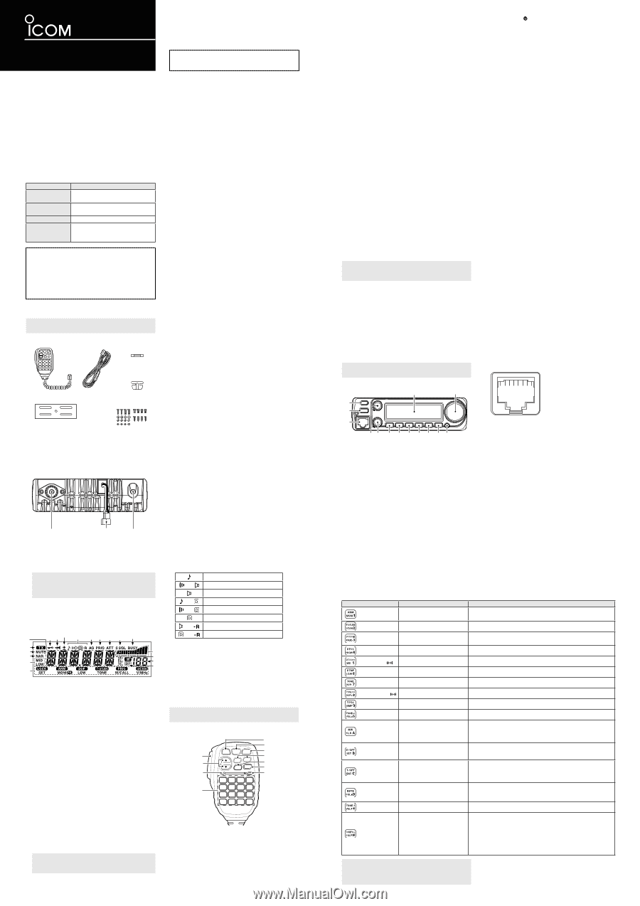
1
+8 V DC output
(Maximum 35 mA)
2
Channel up/down
3
8 V control IN
4
PTT
5
GND (microphone ground)
6
MIC (microphone input)
7
GND
8
Data IN
D
Microphone connector information
D
HM-133V Keypad
KEY
FUNCTION
SECONDARY FUNCTION ([FUNC]+key)
[MONI 1 ANM]
Opens or closes the squelch.
In the Memory mode, turns the channel names or number display
ON or OFF.
[SCAN 2 T-SCAN]
Starts or stops scanning.
Starts and stops a Tone scan.
[PRIO 3 PTT-M]
Starts or stops a Priority
Watch.
Turns the One-Touch PTT function ON or OFF.
See the Advanced manual for details.
[HIGH 4 DTCS]
Selects the high output power.
Turns ON the DTCS Squelch function.
[MID 5 DTCS
]
Selects the middle output power.
Turns ON the DTCS Pocket Beep function.
[LOW 6 DTMF]
Selects the low output power.
Turns ON the DTMF Memory encoder.
[DUP- 7 TONE]
Selects the minus Duplex mode.
Turns ON the subaudible tone encoder.
[DUP+ 8 TSQL
]
Selects the plus Duplex mode.
Turns ON the CTCSS Pocket Beep function.
[SIMP 9 TSQL]
Selects the Simplex mode.
Turns ON the Tone Squelch function.
[VOL▲ 0 TONE-2]
Turns up the audio level.
Sends a 1750 Hz tone while holding down.
[CLR A MW]
•
Cancels frequency entry.
•
Cancels a scan or a Priority
Watch.
•
Exits the Set mode.
•
Selects the Memory Channel Programming mode.
•
Advances the Memory channel number when continuously
pushed after programming is completed.
[SET B D-OFF]
•
Enters the Set mode.
•
Selects the next item in the
Set mode.
Turns OFF the DTMF Memory mode.
[ENT C T-OFF]
•
Sets the keypad for numeral
input.
•
Selects the previous item in
the Set mode.
Turns OFF the DTCS/Tone squelch function, DTCS/CTCSS pocket
beep function, or subaudible tone encoder.
[SQL▲ D MUTE]
Turns up the squelch level.
Turn the Audio Mute function ON or OFF.
When the function is ON, “
MUTE
” is displayed.
If any operation is performed, the function is turned OFF.
[VOL▼
TONE-1]
Turns down the audio level.
Sends a 1750 Hz tone for 1 second.
[SQL▼ # 16KEY-L]
Turns down the squelch level.
Turn the Microphone Keypad Lock function ON or OFF.
When the function is ON, the activity indicator lights orange and
the digit keys on the keypad (including the [A] to [D], [
], and [#]
keys) are locked.
Other keys and all keys on the transceiver can be used.
If the transceiver is turned OFF with this function ON, the function
will remain ON even after the transceiver is turned ON again.
1
2
3
1 2 3 4
8
7
6
5
#
S/RF INDICATOR
Displays the relative signal strength while receiving signals.
Displays the output power level while transmitting.
.
BUSY ICON
Displayed while receiving a signal or the squelch is open.
Blinks when the Monitor function is ON.
,
S-METER SQUELCH ICON
Displayed when the S-meter Squelch function is ON.
D
SQUELCH ATTENUATOR ICON
Displayed when the Squelch Attenuator function is ON.
F
PRIORITY WATCH ICON
Displayed during a Priority Watch.
G
AUTO POWER OFF ICON
Displayed when the Auto Power OFF function is ON.
H
TONE ICONS
Displayed when the Tone function is ON.
Push [TONE T-SCAN] to select the tone function.
Subaudible tone encoder (TX only)
and
CTCSS Pocket Beep function
CTCSS Squelch function
and
DTCS encoder (only TX)
and
DTCS Pocket Beep function
DTCS Squelch function
and
Reverse CTCSS Squelch function
and
Reverse DTCS Squelch function
I
DUPLEX ICONS
A “
+
” is displayed when in the plus Duplex mode.
A “
–
” is displayed when in the minus Duplex mode.
J
FOGHORN ICON
Displayed when the Foghorn function is ON.
K
LOCK ICON
Displayed when the Lock function is ON.
1
PTT SWITCH
Hold down to transmit, release to receive.
Push to switch between transmission and reception
when the One-Touch PTT function is ON.
2
UP/DOWN KEYS [▲] or [▼]
Push to select the operating frequency, Memory
channel, mode setting, and so on.
Hold down either key for 1 second to start scanning.
The scanning direction follows the direction of the
key’s arrow.
1
3
2
5
6
7
8
9
#
.
4
3
ACTIVITY INDICATOR
Lights red when any key other than [FUNC] or
[DTMF-S] is pushed, or while transmitting.
Lights orange when the Microphone Keypad Lock
function is ON.
Lights green when the One-Touch PTT function is ON.
4
KEYPAD
Push the keys to activate various functions.
5
FUNCTION INDICATOR
Lights orange when [FUNC] is activated—indicating
the secondary function of keys can be used.
Lights green when [DTMF-S] is activated—DTMF
signals can be transmitted using the keypad.
6
FUNCTION KEY [FUNC]
Push this key and then push the keypad to turn the
secondary function ON or OFF.
7
DTMF MEMORY SELECT KEY [DTMF-S]
Push to turn ON the DTMF direct selection.
See the table below for details.
D
Function display
1
FREQUENCY READOUT
Displays the operating frequency, channel name, Set
mode contents, and so on.
The frequency decimal point blinks during a scan.
In the DTMF Memory mode, “d” is displayed in the 100
MHz digits.
2
TRANSMIT ICON
Displayed while transmitting.
Blinks while transmitting when the One-Touch PTT
function is ON.
3
AUDIO MUTE ICON
Displayed when the Audio Mute function is ON.
4
NARROW MODE ICON
Displayed when “Narrow” is selected in the Wide/Narrow
setting.
5
OUTPUT POWER ICONS
Displays the selected output power level.
If no output power icon is displayed, the level is set to
“High.”
6
KEY ICONS
Displays the functions of the keys directly below the
function display.
7
SKIP ICON
Displayed when the selected Memory channel is set as a
Skip channel.
8
Memory channel NUMBER READOUT
Displays the selected Memory channel number.
A “C” is displayed when the Call channel is selected.
NOTE:
When the VFO mode is selected from the Call
Channel mode, a small “c” is displayed instead of the
Memory channel number.
9
MEMORY ICON
Displayed when the Memory mode is selected.
D
HM-133V
°
Supplied accessories
NOTE:
Some accessories may not be supplied, or the
shape may differ, depending on the transceiver version.
Microphone
Spare Fuse
(125 V 15 A)
DC Power Cable (3 m)
Mobile mounting bracket
Mounting screws, nuts,
and washers
Microphone
hanger
1
3
2
5
6 7 8 9 #
.
,
4
D
Function display
°
Microphone
NOTE:
The supplied microphone is different,
depending on the transceiver version.
8
FUNCTION KEYS [F-1] and [F-2]
Push to activate the assigned settings.
9
BANK/OPTION KEY [BANK/OPTION]
In the Memory mode, push to select the memory bank
option.
In the Marine Channel mode, hold down for 1 second
to select the Marine Set mode.
In the Marine Set mode, push to select the next item.
Hold down for 1 second to select the Option Set mode.
When the Emergency Call function or the Temporary
Volume function is assigned, each function is turned
ON.
#
MEMORY/CALL KEY [MR/CALL]
Push to select the Memory mode.
Hold down for 1 second to select the Call channel.
In the Marine Set mode, push to select the previous item.
.
VFO/LOCK KEY [VFO/LOCK]
Push to select the VFO mode.
Hold down for 1 second to turn the Lock function ON
or OFF.
NOTE:
After pushing [DTMF-S], transmits the appropriate
DTMF code. When the DTMF Memory encoder is turned
ON, push [A] to [D], [
], [#], or [0] to [9] to transmit the
appropriate DTMF Memory contents.
When the audio level or the squelch level is changed from
the HM-133V, the level will be displayed in the Memory
channel number readout and the S/RF indicator. See the
Advanced manual for details.
The output level cannot be changed from the HM-133V
while transmitting.
8
9
.
,
D
F
G
J
K
2
3
4
5
6
H
I
#
1
7
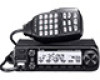
Thank you for choosing this Icom product.
READ ALL INSTRUCTIONS
carefully and completely
before using this product.
CAUTION: DO NOT
use harsh solvents such as Benzine or
alcohol when cleaning. This could damage the equipment
surfaces. If the surface becomes dusty or dirty, wipe it clean
with a soft, dry cloth.
CAUTION: DO NOT
use or leave the transceiver in areas
with temperatures below −10°C or above +60°C, or in areas
exposed to direct sunlight, such as the dashboard.
CAUTION: DO NOT
use or leave the transceiver in excessively
dusty environments. This could damage the transceiver.
CAUTION: DO NOT
use the non-specified microphone.
Other microphones have different pin assignments and may
damage the transceiver.
NEVER
place the transceiver in an insecure place to avoid
inadvertent use by unauthorized persons.
DO NOT
push PTT unless you actually intend to transmit.
DO NOT
place the transceiver where hot or cold air blows
directly onto it, during mobile operation.
NOTE:
During maritime mobile operation, keep the transceiver
and microphone as far away as possible from the magnetic
navigation compass to prevent erroneous indications.
°
FCC information
This equipment has been tested and found to comply with
the limits for a Class B digital device, pursuant to part 15
of the FCC Rules. These limits are designed to provide
reasonable protection against harmful interference in a
residential installation. This equipment generates, uses, and
can radiate radio frequency energy and, if not installed and
used in accordance with the instructions, may cause harmful
interference to radio communications. However, there is
no guarantee that interference will not occur in a particular
installation. If this equipment does cause harmful interference
to radio or television reception, which can be determined by
turning the equipment off
and on, the user is encouraged to try
to correct the interference by several of the following measures:
•
Reorient or relocate the receiving antenna.
•
Increase the separation between the equipment and receiver.
•
Connect the equipment into an outlet on a circuit different
from that to which the receiver is connected.
•
Consult the dealer or an experienced radio/TV technician
for help.
CAUTION:
Changes or modifications to this transceiver,
not expressly approved by Icom Inc., could void your
authority to operate this transceiver under FCC regulations.
This device complies with part 15 of the FCC Rules.
Operation is subject to the condition that this device does
not cause harmful interference.
°
Canada information
This device complies with Industry Canada license-exempt
RSS standard(s). Operation is subject to the following two
conditions: (1) this device may not cause interference, and (2)
this device must accept any interference, including interference
that may cause undesired operation of the device.
°
Panel description
NOTE:
The Marine and Weather Channel mode may
not be used, depending on the transceiver version.
1
POWER KEY [
]
Hold down for 1 second to turn the transceiver ON or OFF.
2
MEMORY WRITE KEY [S.MW MW]
Push to enter the Memory Write mode.
Hold down for 1 second to set the selected Memory
channel.
Continue to hold down the key to automatically
increment the Memory channels.
3
MICROPHONE CONNECTOR
Connects to the supplied microphone.
4
VOLUME CONTROL [VOL]
Rotate to adjust the audio level.
5
SQUELCH CONTROL [SQL]
Rotate to adjust the squelch level.
The S-meter squelch or attenuator squelch is activated
when rotating [SQL] right from the 12 o’clock position.
6
SET•LOCK KEY [SET LOCK]
Push to enter to the Set mode.
Hold down for 1 second to turn the Lock function ON
or OFF.
7
MONITOR•CHANNEL NAME•PA KEY [MONI ANM PA]
Push to turn the monitor function ON or OFF.
In the Memory or Call Channel mode, hold down for 1
second to turn the channel name or number ON or OFF.
In the Marine Channel mode, hold down for 1 second
to turn the Public Address function ON or OFF.
8
OUTPUT POWER•DUPLEX KEY [LOW DUP]
Push to select the output power.
Hold down for 1 second to select the minus Duplex,
plus Duplex, or Simplex mode.
9
TONE•TONE SCAN KEY [TONE T-SCAN]
Push to select the Tone function.
Hold down for 1 second to start a Tone scan.
#
MEMORY/CALL•PRIORITY KEY [M/CALL PRIO]
Push to select the Memory, Call, Marine, or Weather
Channel mode.
Hold down for 1 second to start a Priority Watch.
.
VFO/MHz TUNING•SCAN KEY [V/MHz SCAN]
Push to select the VFO mode.
In the VFO mode, push to select the
10 MHz or 1 MHz
tuning step.
Hold down for 1 second to start a scan.
Push to cancel a scan.
,
BANK•OPTION KEY [BANK OPT]
In the Memory mode, push to select a memory bank.
Hold down for 1 second to enter the Option Set mode.
In the Marine Channel mode, hold down for 1 second
to enter the Marine Set mode.
You can assign the Emergency Call function or the
Temporary Volume function to this key. See the
Advanced manual for details.
D
TUNING DIAL [DIAL]
Select the operating frequency or Memory channel.
Select an option in the Set mode.
Change the scanning direction.
D
Front panel
|V3500
FM TRANSCEIVER