Icom VE-PG3 Installation Guide
Icom VE-PG3 Manual
 |
View all Icom VE-PG3 manuals
Add to My Manuals
Save this manual to your list of manuals |
Icom VE-PG3 manual content summary:
- Icom VE-PG3 | Installation Guide - Page 1
RoIP GATEWAY INSTALLATION 1 Continued from the separate leaflet "PREPARATION." Step 3 Configure the network Read the "PRECAUTIONS" leaflet first, if you have not done so. Thank you for purchasing the VE-PG3. The VE-PG3 is a network converter that allows you to connect Icom radios or repeaters to a - Icom VE-PG3 | Installation Guide - Page 2
related settings are returned to their default. • See the VE-PG3 instruction manual for details. When using in the Bridge mode Area A Area B w Verify !1 Configure the VE-PG3 in area B, by following the same procedure. When using in the Converter mode Area A Extension number 301 2012 Icom Inc.
-
 1
1 -
 2
2
 |
 |
(Continued on the back side.)
Î
Step 3
Configure the network
Step 3
Configure the network (continued)
RoIP GATEWAY
INSTALLATION 1
Thank you for purchasing the VE-PG3. The VE-PG3 is a
network converter that allows you to connect Icom radios
or repeaters to a VoIP network.
This guide describes the basic settings to operate the VE-PG3.
READ ALL INSTRUCTIONS carefully and completely be-
fore using.
HUB
To the [DC] jack
To the [LAN] port
To the ground terminal
LAN cable**
(Purchase separately)
Ground wire
(Purchase
separately)
AC adaptor
(Supplied with the VE-PG3)
AC outlet
PC
(Example of the IP address;
192.168.0.100)
Ground
terminal
e
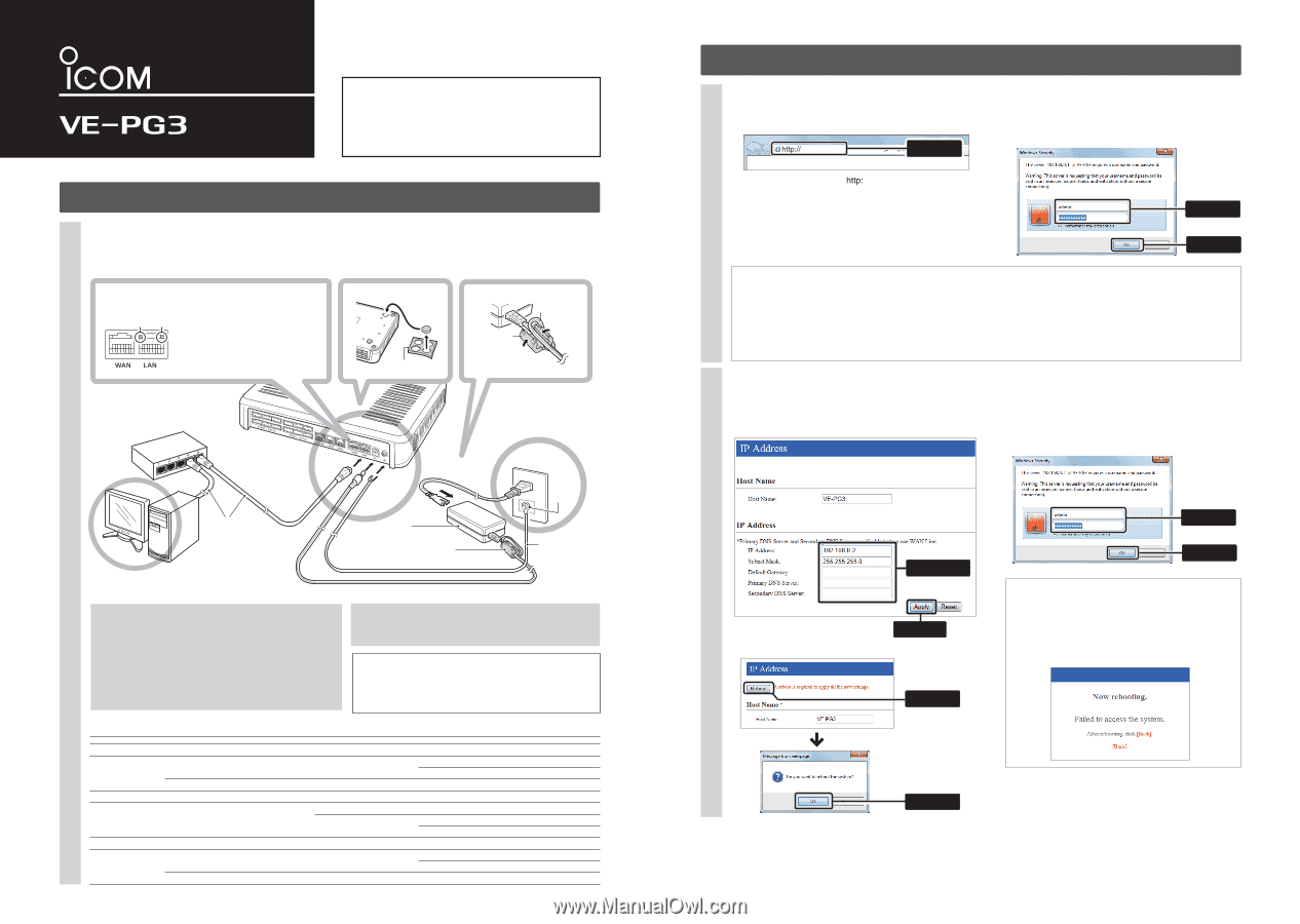
Connect the cables
Connect the power supply
r
Boot the PC
t
The [PWR/MSG] LED on the front
panel lights*.
*The indication may differ, depending on the setting.
**Category 5 or higher.
Verify that the LEDs light
y
When the [LAN] LEDs on the rear don’t light, verify that the LAN
cable is securely connected.
Attach the cushions
q
Cushion Sheet
(Supplied with the VE-PG3)
Attach the ferrite EMI filter
w
q
w
LED indication:
q
Lights: Full duplex
Doesn’t light: Half duplex
w
Lights: Connected to the network
Blinks: While the line is communicating
Ferrite EMI filter
(Supplied with the VE-PG3)
Ferrite EMI filter
(Supplied with
the VE-PG3)
Wrap the cable once around
the ferrite EMI filter.
Power cable
R
WARNING!
To prevent electrical shock, television interference (TVI),
broadcast interference (BCI) and other problems, ground the
VE-PG3 through the ground terminal.
For best results, connect a heavy gauge wire or strap to a ground
terminal of an AC outlet or a long ground rod. Make the distance
between the ground terminal and ground as short as possible.
NEVER connect the ground terminal to a gas or electric pipe.
This may result in an electrical shock or cause a fire.
Setting the PC IP address
Set the static PC IP address (example: 192.168.0.100).
See the PC's instruction manual for the setting details.
Set the static VE-PG3 IP address assigned by the network
administrator.
Connect the devices to the VE-PG3 in order of
q
to
y
.
• Do not connect to the IP network before the configuration is finished.
• A HUB which supports 100BASE-TX or better is recommended. Otherwise, an unexpected failure of communication may be caused.
• The VE-PG3 can be directly connected to the PC using a MDI-X (crossover) type Ethernet cable.
The following procedures (
q
to
e
) describe how to access the VE-PG3 setting screen using a web browser.
Following the procedure below, set the VE-PG3 IP address according to your network environment.
• Do not set the IP address to one that is already used for another network device.
1
2
3
q
Open your web browser, then enter the IP address of
the VE-PG3 into the address bar.
*The default IP address is “
//192.168.0.1/.”
w
Push the [ENTER] key.
• The Login Authentication screen will appear.
e
Enter “admin” (fixed username) and “admin” (default
password) in their respective input fields on the Login
Authentication screen, and then click [OK].
q
Click the [Network] menu, and then click [IP Address].
w
Enter the VE-PG3 IP address, and then click <Apply>.
e
Click <Reboot> to reboot the VE-PG3.
r
After rebooting, enter “admin” (fixed username) and
“admin” (default password) in their respective input
fields on the Login Authentication screen, and then
click [OK].
To prevent unauthorized access
You must be careful when choosing your password, and
change it occasionally.
See the VE-PG3 instruction manual for the password setting.
• Choose one that is not easy to guess.
• Use numbers, characters and letters (both lower and upper case).
About web browsers
Only Microsoft Internet Explorer 9 or later must be used
with the VE-PG3.
Activate the JavaScript and set to allow Cookies on your
web browser to correctly display the setting screen.
If other browsers are used, the screen may not be correctly
displayed.
Menu Item
Setting Screen
Setting Item
Item Name
Value
Network
IP Address
IP Address
IP Address
192.168.0.1
Subnet Mask
255.255.255.0
DHCP Server
DHCP Server
DHCP Server
Disable
Router
WAN
Connection Type
Connection Type
No Connection
Operating Mode
Operating Mode
Operating Mode
Operating Mode
Bridge
EXT I/O Port Mode
Connection Unit
EXT I/O Unit
EXT I/O Port Mode
Separate
Port Settings
Transceiver 1 (TRX1)/Transceiver 2 (TRX2)
Transceiver Model
Transceiver Model
IC-F5060/F6060
Management
Administrator
Administrator
Username
admin (fixed)
Current Password:
admin (lower case)
Firmware Update
Automatic Update
Automatic Update
Enable
Network and System default settings
About the IP address
If the network part of the PC IP address is different from
that of the VE-PG3, you cannot access the VE-PG3
setting screen.
If the following message is displayed on the screen after
the rebooting, change the PC IP address according to
your network environment, and then click [Back].
Continued from the separate leaflet “PREPARATION.”
192.168.0.1/
Enter
Read the “PRECAUTIONS” leaflet first, if you have not done so.
q
Click
w
Click
R
WARNING!
NEVER
use other than the specified AC adapter. This may result
in an electrical shock, cause a fire or damage the VE-PG3.
q
Enter
w
Click
q
Enter
w
Click
q
Configure
w
Click