Image Fitness 8.25 Elliptical English Manual - Page 6
Tighten the two M10 Nylon Locknuts
 |
View all Image Fitness 8.25 Elliptical manuals
Add to My Manuals
Save this manual to your list of manuals |
Page 6 highlights
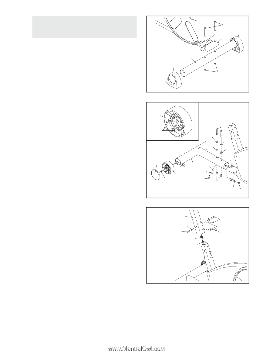
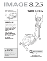
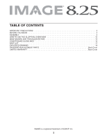
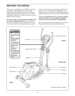
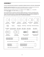
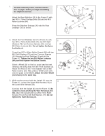
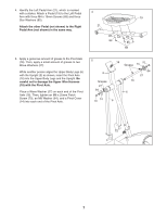
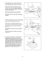
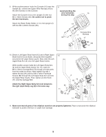
1. To make assembly easier, read the informa- 1 tion on page 5 before you begin assembling the elliptical exerciser. Attach the Rear Stabilizer (35) to the Frame (1) with two M10 x 75mm Carriage Bolts (58) and two M10 Nylon Locknuts (84). Press the Stabilizer Endcaps (36) onto the Rear Stabilizer (35) as shown. 35 36 58 36 1 84 2. Attach the Front Stabilizer (3) to the Frame (1) with two M10 x 76mm Button Bolts (74), two M10 Split Washers (78), two Concave Spacers (65), and two M10 Nylon Locknuts (84). Do not tighten the Nylon Locknuts yet. Thread two M10 x 60mm Button Screws (66) with two M10 Split Washers (78) and two Concave Spacers (65) through the Front Stabilizer (3) and into the Frame (1). Tighten the two M10 Nylon Locknuts (84), and then tighten the Button Screws. Orient a Wheel (28) so the four posts (see the inset drawing) are facing away from the Front Stabilizer (3). Attach the Wheel to the Front Stabilizer with an M8 Nylon Locknut (59). Next, press a Wheel Cover (29) onto the posts on the Wheel. Attach the other Wheel (not shown) in the same way. 2 28 Posts 29 28 59 74 78 78 65 65 1 3 65 78 66 84 65 78 66 3. While another person holds the Upright (2) near the 3 Frame (1), connect the Upper Wire Harness (18) to the Lower Wire Harness (38). Carefully slide the Upright (2) onto the Frame (1). Be careful to avoid pinching the Wire Harnesses (18, 38). Attach the Upright with four M8 x 19mm Patch Screws (73) and four M8 Split Washers (79). Do not tighten the Patch Screws yet. 2 79 79 73 18 38 73 79 73 1 6
-
 1
1 -
 2
2 -
 3
3 -
 4
4 -
 5
5 -
 6
6 -
 7
7 -
 8
8 -
 9
9 -
 10
10 -
 11
11 -
 12
12 -
13
-
14
-
15
-
16
-
17
-
18
-
19
-
20
 |
 |