Intel 925 Data Sheet - Page 125
INTRLINE1-Interrupt Line D1:F0, INTRPIN1-Interrupt Pin D1:F0
 |
UPC - 683728067724
View all Intel 925 manuals
Add to My Manuals
Save this manual to your list of manuals |
Page 125 highlights
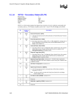
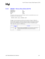
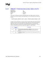
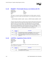
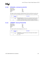
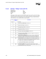
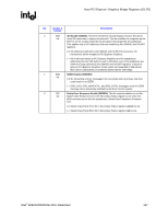
Host-PCI Express* Graphics Bridge Registers (D1:F0) R 8.1.20 INTRLINE1-Interrupt Line (D1:F0) PCI Device: Address Offset: Default Value: Access: Size: 1 3Ch 00h R/W 8 bits This register contains interrupt line routing information. The device itself does not use this value; rather device drivers and operating systems use it to determine priority and vector information. Bit Access & Default Description 7:0 R/W Interrupt Connection: This field is used to communicate interrupt line routing 00h information. POST software writes the routing information into this register as it initializes and configures the system. The value in this register indicates which input of the system interrupt controller this device's interrupt pin is connected to. 8.1.21 INTRPIN1-Interrupt Pin (D1:F0) PCI Device: Address Offset: Default Value: Access: Size: 1 3Dh 00h RO 8 bits This register specifies which interrupt pin this device uses. Bit Access & Default Description 7:0 RO Interrupt Pin: As a single function device, the PCI Express* device specifies 01h INTA as its interrupt pin. 01h = INTA Intel® 82925X/82925XE MCH Datasheet 125
-
 1
1 -
2
-
3
-
4
-
5
-
6
-
7
-
8
-
9
-
10
-
11
-
12
-
13
-
14
-
15
-
16
-
17
-
18
-
19
-
20
-
21
-
22
-
23
-
24
-
25
-
26
-
27
-
28
-
29
-
30
-
31
-
32
-
33
-
34
-
35
-
36
-
37
-
38
-
39
-
40
-
41
-
42
-
43
-
44
-
45
-
46
-
47
-
48
-
49
-
50
-
51
-
52
-
53
-
54
-
55
-
56
-
57
-
58
-
59
-
60
-
61
-
62
-
63
-
64
-
65
-
66
-
67
-
68
-
69
-
70
-
71
-
72
-
73
-
74
-
75
-
76
-
77
-
78
-
79
-
80
-
81
-
82
-
83
-
84
-
85
-
86
-
87
-
88
-
89
-
90
-
91
-
92
-
93
-
94
-
95
-
96
-
97
-
98
-
99
-
100
-
101
-
102
-
103
-
104
-
105
-
106
-
107
-
108
-
109
-
110
-
111
-
112
-
113
-
114
-
115
-
116
-
117
-
118
-
119
-
 120
120 -
 121
121 -
 122
122 -
 123
123 -
 124
124 -
 125
125 -
 126
126 -
 127
127 -
 128
128 -
 129
129 -
 130
130 -
131
-
132
-
133
-
134
-
135
-
136
-
137
-
138
-
139
-
140
-
141
-
142
-
143
-
144
-
145
-
146
-
147
-
148
-
149
-
150
-
151
-
152
-
153
-
154
-
155
-
156
-
157
-
158
-
159
-
160
-
161
-
162
-
163
-
164
-
165
-
166
-
167
-
168
-
169
-
170
-
171
-
172
-
173
-
174
-
175
-
176
-
177
-
178
-
179
-
180
-
181
-
182
-
183
-
184
-
185
-
186
-
187
-
188
-
189
-
190
-
191
-
192
-
193
-
194
-
195
-
196
-
197
-
198
-
199
-
200
-
201
-
202
-
203
-
204
-
205
-
206
-
207
-
208
-
209
-
210
-
211
-
212
-
213
-
214
-
215
-
216
-
217
-
218
-
219
-
220
-
221
-
222
-
223
-
224
-
225
-
226
-
227
-
228
-
229
-
230
-
231
-
232
-
233
-
234
-
235
-
236
-
237
-
238
-
239
-
240
-
241
-
242
 |
 |