Intel 925 Data Sheet - Page 141
SLOTCAP-Slot Capabilities D1:F0
 |
UPC - 683728067724
View all Intel 925 manuals
Add to My Manuals
Save this manual to your list of manuals |
Page 141 highlights
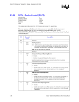
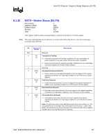
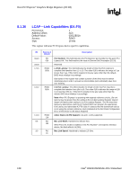
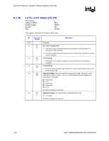
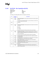
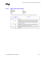
Host-PCI Express* Graphics Bridge Registers (D1:F0) R 8.1.39 SLOTCAP-Slot Capabilities (D1:F0) PCI Device: Address Offset: Default Value: Access: Size: 1 B4h 00000000h R/WO 32 bits PCI Express slot-related registers allow for the support of Hot-Plug. Bit 31:19 18:17 Access & Default R/WO 0000h Description Physical Slot Number: This field indicates the physical slot number attached to this Port. This field must be initialized by BIOS to a value that assigns a slot number that is globally unique within the chassis. Reserved 16:15 14:7 6 5 4 3 2:1 0 R/WO 00b R/WO 00h R/WO 0b R/WO 0b R/WO 0b R/WO 0b R/WO 0b Slot Power Limit Scale: This field specifies the scale used for the Slot Power Limit Value. 00 = 1.0x 01 = 0.1x 10 = 0.01x 11 = 0.001x If this field is written, the link sends a Set_Slot_Power_Limit message. Slot Power Limit Value: In combination with the Slot Power Limit Scale value, this field specifies the upper limit on power supplied by slot. Power limit (in Watts) is calculated by multiplying the value in this field by the value in the Slot Power Limit Scale field. If this field is written, the link sends a Set_Slot_Power_Limit message. Hot-plug Capable: This field indicates that this slot is capable of supporting Hot-plug operations. Hot-plug Surprise: This field indicates that a device present in this slot might be removed from the system without any prior notification. Power Indicator Present: This field indicates that a Power Indicator is implemented on the chassis for this slot. Attention Indicator Present: This field indicates that an Attention Indicator is implemented on the chassis for this slot. Reserved Attention Button Present: This field indicates that an Attention Button is implemented on the chassis for this slot. The Attention Button allows the user to request hot-plug operations. Intel® 82925X/82925XE MCH Datasheet 141
-
 1
1 -
2
-
3
-
4
-
5
-
6
-
7
-
8
-
9
-
10
-
11
-
12
-
13
-
14
-
15
-
16
-
17
-
18
-
19
-
20
-
21
-
22
-
23
-
24
-
25
-
26
-
27
-
28
-
29
-
30
-
31
-
32
-
33
-
34
-
35
-
36
-
37
-
38
-
39
-
40
-
41
-
42
-
43
-
44
-
45
-
46
-
47
-
48
-
49
-
50
-
51
-
52
-
53
-
54
-
55
-
56
-
57
-
58
-
59
-
60
-
61
-
62
-
63
-
64
-
65
-
66
-
67
-
68
-
69
-
70
-
71
-
72
-
73
-
74
-
75
-
76
-
77
-
78
-
79
-
80
-
81
-
82
-
83
-
84
-
85
-
86
-
87
-
88
-
89
-
90
-
91
-
92
-
93
-
94
-
95
-
96
-
97
-
98
-
99
-
100
-
101
-
102
-
103
-
104
-
105
-
106
-
107
-
108
-
109
-
110
-
111
-
112
-
113
-
114
-
115
-
116
-
117
-
118
-
119
-
120
-
121
-
122
-
123
-
124
-
125
-
126
-
127
-
128
-
129
-
130
-
131
-
132
-
133
-
134
-
135
-
 136
136 -
 137
137 -
 138
138 -
 139
139 -
 140
140 -
 141
141 -
 142
142 -
 143
143 -
 144
144 -
 145
145 -
 146
146 -
147
-
148
-
149
-
150
-
151
-
152
-
153
-
154
-
155
-
156
-
157
-
158
-
159
-
160
-
161
-
162
-
163
-
164
-
165
-
166
-
167
-
168
-
169
-
170
-
171
-
172
-
173
-
174
-
175
-
176
-
177
-
178
-
179
-
180
-
181
-
182
-
183
-
184
-
185
-
186
-
187
-
188
-
189
-
190
-
191
-
192
-
193
-
194
-
195
-
196
-
197
-
198
-
199
-
200
-
201
-
202
-
203
-
204
-
205
-
206
-
207
-
208
-
209
-
210
-
211
-
212
-
213
-
214
-
215
-
216
-
217
-
218
-
219
-
220
-
221
-
222
-
223
-
224
-
225
-
226
-
227
-
228
-
229
-
230
-
231
-
232
-
233
-
234
-
235
-
236
-
237
-
238
-
239
-
240
-
241
-
242
 |
 |
