Intel 925 Data Sheet - Page 152
VC1RSTS-VC1 Resource Status D1:F0, RCLDECH-Root Complex Link Declaration Enhanced
 |
UPC - 683728067724
View all Intel 925 manuals
Add to My Manuals
Save this manual to your list of manuals |
Page 152 highlights
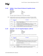
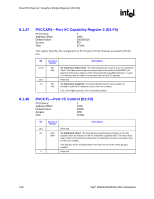
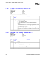
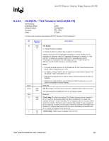
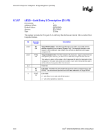
Host-PCI Express* Graphics Bridge Registers (D1:F0) R 8.1.54 VC1RSTS-VC1 Resource Status (D1:F0) PCI Device: Address Offset: Default Value: Access: Size: 1 126h 0000h RO 16 bits This register reports the Virtual Channel specific status. Bit Access & Default Description 15:2 Reserved 1 RO VC1 Negotiation Pending 1b 0 = The VC negotiation is complete. 1 = The VC resource is still in the process of negotiation (initialization or disabling). This bit indicates the status of the process of Flow Control initialization. It is set by default on Reset, as well as when the corresponding Virtual Channel is Disabled or the Link is in the DL_Down state. It is cleared when the link successfully exits the FC_INIT2 state Before using a Virtual Channel, software must check whether the VC Negotiation Pending fields for that Virtual Channel are cleared in both Components on a Link. 0 Reserved 8.1.55 RCLDECH-Root Complex Link Declaration Enhanced Capability Header (D1:F0) PCI Device: Address Offset: Default Value: Access: Size: 1 140h 00010005h RO 32 bits This capability declares links from this element (PCI Express* x16 Graphics Interface) to other elements of the root complex component to which it belongs. See the PCI Express specification for link/topology declaration requirements. Bit 31:20 19:16 15:0 Access & Default Description RO 000h RO 1h RO 0005h Pointer to Next Capability: This is the last capability in the PCI Express* extended capabilities list. Link Declaration Capability Version: Hardwired to 1 to indicate compliances with the 1.0a version of the PCI Express specification. Extended Capability ID: Value of 0005h identifies this linked list item (capability structure) as being for PCI Express Link Declaration Capability. Note: See corresponding Egress Port Link Declaration Capability registers for diagram of Link Declaration Topology. 152 Intel® 82925X/82925XE MCH Datasheet
-
 1
1 -
2
-
3
-
4
-
5
-
6
-
7
-
8
-
9
-
10
-
11
-
12
-
13
-
14
-
15
-
16
-
17
-
18
-
19
-
20
-
21
-
22
-
23
-
24
-
25
-
26
-
27
-
28
-
29
-
30
-
31
-
32
-
33
-
34
-
35
-
36
-
37
-
38
-
39
-
40
-
41
-
42
-
43
-
44
-
45
-
46
-
47
-
48
-
49
-
50
-
51
-
52
-
53
-
54
-
55
-
56
-
57
-
58
-
59
-
60
-
61
-
62
-
63
-
64
-
65
-
66
-
67
-
68
-
69
-
70
-
71
-
72
-
73
-
74
-
75
-
76
-
77
-
78
-
79
-
80
-
81
-
82
-
83
-
84
-
85
-
86
-
87
-
88
-
89
-
90
-
91
-
92
-
93
-
94
-
95
-
96
-
97
-
98
-
99
-
100
-
101
-
102
-
103
-
104
-
105
-
106
-
107
-
108
-
109
-
110
-
111
-
112
-
113
-
114
-
115
-
116
-
117
-
118
-
119
-
120
-
121
-
122
-
123
-
124
-
125
-
126
-
127
-
128
-
129
-
130
-
131
-
132
-
133
-
134
-
135
-
136
-
137
-
138
-
139
-
140
-
141
-
142
-
143
-
144
-
145
-
146
-
 147
147 -
 148
148 -
 149
149 -
 150
150 -
 151
151 -
 152
152 -
 153
153 -
 154
154 -
 155
155 -
 156
156 -
 157
157 -
158
-
159
-
160
-
161
-
162
-
163
-
164
-
165
-
166
-
167
-
168
-
169
-
170
-
171
-
172
-
173
-
174
-
175
-
176
-
177
-
178
-
179
-
180
-
181
-
182
-
183
-
184
-
185
-
186
-
187
-
188
-
189
-
190
-
191
-
192
-
193
-
194
-
195
-
196
-
197
-
198
-
199
-
200
-
201
-
202
-
203
-
204
-
205
-
206
-
207
-
208
-
209
-
210
-
211
-
212
-
213
-
214
-
215
-
216
-
217
-
218
-
219
-
220
-
221
-
222
-
223
-
224
-
225
-
226
-
227
-
228
-
229
-
230
-
231
-
232
-
233
-
234
-
235
-
236
-
237
-
238
-
239
-
240
-
241
-
242
 |
 |