Intel 925 Data Sheet - Page 174
System Memory Controller, APIC Cluster Mode Support, Memory Organization Modes
 |
UPC - 683728067724
View all Intel 925 manuals
Add to My Manuals
Save this manual to your list of manuals |
Page 174 highlights
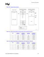
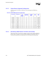
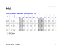
Functional Description R 10.1.3 10.2 10.2.1 the MCH receives data, it monitors HDINV[3:0]# to determine if the corresponding data segment should be inverted. APIC Cluster Mode Support This is required for backwards compatibility with existing software, including various operating systems. As one example, beginning with Microsoft Windows 2000 there is a mode (boot.ini) that allows an end user to enable the use of cluster addressing support of the APIC. The MCH supports three types of interrupt re-direction: • Physical • Flat-Logical • Clustered-Logical System Memory Controller This section describes the MCH system memory interface for DDR2 memory. The MCH supports DDR2 memory and either one or two DIMMs per channel. Memory Organization Modes The system memory controller supports two styles of memory organization (Interleaved and Asymmetric). Rules for populating DIMM slots are included in this chapter. Interleaved Mode This mode provides maximum performance on real applications. Addresses are ping-ponged between the channels, and the switch happens after each cache line (64 byte boundary). If two consecutive cache lines are requested, both may be retrieved simultaneously, since they are guaranteed to be on opposite channels. The drawbacks of Interleaved Mode are that the system designer must populate both channels of memory such that they have equal capacity, but the technology and device width may vary from one channel to the other. Refer to Figure 10-1 for further clarification. Asymmetric Mode This mode trades performance for system design flexibility. Unlike the previous mode, addresses start in channel A and stay there until the end of the highest rank in channel A; then, addresses continue from the bottom of channel B to the top. Real world applications are unlikely to make requests that alternate between addresses that sit on opposite channels with this memory organization, so in most cases, bandwidth will be limited to that of a single channel. The system designer is free to populate or not to populate any rank on either channel, including either degenerate single channel case. Refer to Figure 10-1 for further clarification. 174 Intel® 82925X/82925XE MCH Datasheet
-
 1
1 -
2
-
3
-
4
-
5
-
6
-
7
-
8
-
9
-
10
-
11
-
12
-
13
-
14
-
15
-
16
-
17
-
18
-
19
-
20
-
21
-
22
-
23
-
24
-
25
-
26
-
27
-
28
-
29
-
30
-
31
-
32
-
33
-
34
-
35
-
36
-
37
-
38
-
39
-
40
-
41
-
42
-
43
-
44
-
45
-
46
-
47
-
48
-
49
-
50
-
51
-
52
-
53
-
54
-
55
-
56
-
57
-
58
-
59
-
60
-
61
-
62
-
63
-
64
-
65
-
66
-
67
-
68
-
69
-
70
-
71
-
72
-
73
-
74
-
75
-
76
-
77
-
78
-
79
-
80
-
81
-
82
-
83
-
84
-
85
-
86
-
87
-
88
-
89
-
90
-
91
-
92
-
93
-
94
-
95
-
96
-
97
-
98
-
99
-
100
-
101
-
102
-
103
-
104
-
105
-
106
-
107
-
108
-
109
-
110
-
111
-
112
-
113
-
114
-
115
-
116
-
117
-
118
-
119
-
120
-
121
-
122
-
123
-
124
-
125
-
126
-
127
-
128
-
129
-
130
-
131
-
132
-
133
-
134
-
135
-
136
-
137
-
138
-
139
-
140
-
141
-
142
-
143
-
144
-
145
-
146
-
147
-
148
-
149
-
150
-
151
-
152
-
153
-
154
-
155
-
156
-
157
-
158
-
159
-
160
-
161
-
162
-
163
-
164
-
165
-
166
-
167
-
168
-
 169
169 -
 170
170 -
 171
171 -
 172
172 -
 173
173 -
 174
174 -
 175
175 -
 176
176 -
 177
177 -
 178
178 -
 179
179 -
180
-
181
-
182
-
183
-
184
-
185
-
186
-
187
-
188
-
189
-
190
-
191
-
192
-
193
-
194
-
195
-
196
-
197
-
198
-
199
-
200
-
201
-
202
-
203
-
204
-
205
-
206
-
207
-
208
-
209
-
210
-
211
-
212
-
213
-
214
-
215
-
216
-
217
-
218
-
219
-
220
-
221
-
222
-
223
-
224
-
225
-
226
-
227
-
228
-
229
-
230
-
231
-
232
-
233
-
234
-
235
-
236
-
237
-
238
-
239
-
240
-
241
-
242
 |
 |