Intel 925 Data Sheet - Page 185
Electrical Characteristics, Absolute Maximum Ratings
 |
UPC - 683728067724
View all Intel 925 manuals
Add to My Manuals
Save this manual to your list of manuals |
Page 185 highlights
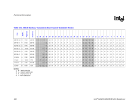
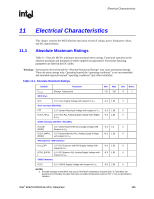
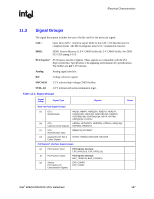
Electrical Characteristics R 11 Electrical Characteristics This chapter contains the MCH absolute maximum electrical ratings, power dissipation values, and DC characteristics. 11.1 Absolute Maximum Ratings Table 11-1 lists the MCH's maximum environmental stress ratings. Functional operation at the absolute maximum and minimum is neither implied nor guaranteed. Functional operating parameters are listed in the DC tables. Warning: Stressing the device beyond the "Absolute Maximum Ratings" may cause permanent damage. These are stress ratings only. Operating beyond the "operating conditions" is not recommended and extended exposure beyond "operating conditions" may affect reliability. Table 11-1. Absolute Maximum Ratings Symbol Parameter Min Max Unit Notes Tstorage MCH Core Storage Temperature -55 150 °C 1 VCC 1.5 V Core Supply Voltage with respect to VSS Host Interface (800 MHz) -0.3 1.65 V VTT 1.2 V System Bus Input Voltage with respect to VSS -0.3 1.65 V VCCA_HPLL 1.5 V Host PLL Analog Supply Voltage with respect -0.3 1.65 V to VSS DDR2 Interface (400 MHz / 533 MHz) VCCSM (DDR2) 1.8 V DDR2 System Memory Supply Voltage with -0.3 4.0 V Respect to VSS VCCA_SMPLL 1.5 V System Memory PLL Analog Supply Voltage -0.3 1.65 V (DDR2) with respect to VSS PCI Express* / DMI Interface VCC_EXP 1.5 V PCI Express* and DMI Supply Voltage with -0.3 1.65 V respect to VSS VCCA_EXPPL 1.5 V PCI Express PLL Analog Supply Voltage with -0.3 1.65 V L respect to VSS CMOS Interface VCC2 2.5 V CMOS Supply Voltage with respect to VSS -0.3 2.65 V NOTES: 1. Possible damage to the MCH may occur if the MCH temperature exceeds 150 °C. Intel does not guarantee functionality for parts that have exceeded temperatures above 150 °C due to specification violation. Intel® 82925X/82925XE MCH Datasheet 185
-
 1
1 -
2
-
3
-
4
-
5
-
6
-
7
-
8
-
9
-
10
-
11
-
12
-
13
-
14
-
15
-
16
-
17
-
18
-
19
-
20
-
21
-
22
-
23
-
24
-
25
-
26
-
27
-
28
-
29
-
30
-
31
-
32
-
33
-
34
-
35
-
36
-
37
-
38
-
39
-
40
-
41
-
42
-
43
-
44
-
45
-
46
-
47
-
48
-
49
-
50
-
51
-
52
-
53
-
54
-
55
-
56
-
57
-
58
-
59
-
60
-
61
-
62
-
63
-
64
-
65
-
66
-
67
-
68
-
69
-
70
-
71
-
72
-
73
-
74
-
75
-
76
-
77
-
78
-
79
-
80
-
81
-
82
-
83
-
84
-
85
-
86
-
87
-
88
-
89
-
90
-
91
-
92
-
93
-
94
-
95
-
96
-
97
-
98
-
99
-
100
-
101
-
102
-
103
-
104
-
105
-
106
-
107
-
108
-
109
-
110
-
111
-
112
-
113
-
114
-
115
-
116
-
117
-
118
-
119
-
120
-
121
-
122
-
123
-
124
-
125
-
126
-
127
-
128
-
129
-
130
-
131
-
132
-
133
-
134
-
135
-
136
-
137
-
138
-
139
-
140
-
141
-
142
-
143
-
144
-
145
-
146
-
147
-
148
-
149
-
150
-
151
-
152
-
153
-
154
-
155
-
156
-
157
-
158
-
159
-
160
-
161
-
162
-
163
-
164
-
165
-
166
-
167
-
168
-
169
-
170
-
171
-
172
-
173
-
174
-
175
-
176
-
177
-
178
-
179
-
 180
180 -
 181
181 -
 182
182 -
 183
183 -
 184
184 -
 185
185 -
 186
186 -
 187
187 -
 188
188 -
 189
189 -
 190
190 -
191
-
192
-
193
-
194
-
195
-
196
-
197
-
198
-
199
-
200
-
201
-
202
-
203
-
204
-
205
-
206
-
207
-
208
-
209
-
210
-
211
-
212
-
213
-
214
-
215
-
216
-
217
-
218
-
219
-
220
-
221
-
222
-
223
-
224
-
225
-
226
-
227
-
228
-
229
-
230
-
231
-
232
-
233
-
234
-
235
-
236
-
237
-
238
-
239
-
240
-
241
-
242
 |
 |