Intel BLKDG33FBC Product Specification
Intel BLKDG33FBC Manual
 |
View all Intel BLKDG33FBC manuals
Add to My Manuals
Save this manual to your list of manuals |
Intel BLKDG33FBC manual content summary:
- Intel BLKDG33FBC | Product Specification - Page 1
May 2007 Order Number: D88105-001US The Intel® Desktop Board DG33FB may contain design defects or errors known as errata that may cause the product to deviate from published specifications. Current characterized errata are documented in the Intel Desktop Board DG33FB Specification Update. - Intel BLKDG33FBC | Product Specification - Page 2
Intel® Desktop Board DG33FB with BIOS identifier DPP3510A.86A. Changes to this specification will be published in the Intel Desktop Board features or instructions marked "reserved" or "undefined." Intel . Intel, the Intel logo, Pentium, Core, and Celeron are registered trademarks of Intel Corporation - Intel BLKDG33FBC | Product Specification - Page 3
the board layout, components, connectors, power and environmental requirements, and the BIOS for the Intel® Desktop Board DG33FB. the hardware used on the board A map of the resources of the board The features supported by the BIOS Setup program A description of the BIOS error messages, beep codes - Intel BLKDG33FBC | Product Specification - Page 4
Intel Desktop Board DG33FB Technical Product Specification Other Common Notation # GB GB/sec Gbit KB Kbit kbits/sec MB MB/sec Mbit Mbit/sec xxh x.x V * Used after a signal - Intel BLKDG33FBC | Product Specification - Page 5
1.1.1 Feature Summary 10 1.1.2 Board Layout 12 1.1.3 Block Diagram 14 1.2 Legacy Considerations 15 1.3 Online Support 15 1.4 Processor 15 1.5 System Memory 16 1.5.1 Memory Configurations 17 1.6 Intel® G33 Express Chipset 19 1.6.1 Intel G33 Graphics Subsystem 19 1.6.2 Intel® Viiv™ Processor - Intel BLKDG33FBC | Product Specification - Page 6
2.5.3 Add-in Board Considerations 53 2.6 Thermal Considerations 54 2.7 Reliability 56 2.8 Environmental 57 3 Overview of BIOS Features 3.1 Introduction 59 3.2 BIOS Flash Memory Organization 60 3.3 Resource Configuration 60 3.3.1 PCI* Autoconfiguration 60 3.3.2 PCI IDE Support 61 3.4 System - Intel BLKDG33FBC | Product Specification - Page 7
49 13. Location of the Jumper Block 50 14. Board Dimensions 51 15. Localized High Temperature Zones 55 Tables 1. Feature Summary 10 2. Board Components Shown in Figure 1 13 3. Supported Memory Configurations 16 4. Audio Jack Support 24 5. LAN Connector LED States 27 6. Effects of Pressing - Intel BLKDG33FBC | Product Specification - Page 8
Intel Desktop Board DG33FB Technical Product Specification 19. Main Power Connector 46 20. Front Panel Header 47 21. States for a One-Color Power LED 48 22. States for a Two-Color Power LED 48 23. Auxiliary Front Panel Power LED Header 48 24. BIOS Setup Configuration Jumper Settings 50 25. - Intel BLKDG33FBC | Product Specification - Page 9
1 Product Description What This Chapter Contains 1.1 Overview 10 1.2 Legacy Considerations 15 1.3 Online Support 15 1.4 Processor 15 1.5 System Memory 16 1.6 Intel® G33 Express Chipset 19 1.7 Parallel IDE Controller 22 1.8 Real-Time Clock Subsystem 22 1.9 Legacy I/O Controller 23 1.10 Audio - Intel BLKDG33FBC | Product Specification - Page 10
1. Feature Summary Form Factor Processor Memory Chipset Video Audio Legacy I/O Control Peripheral Interfaces LAN Support BIOS Instantly Available PC Technology ATX (11.60 inches by 9.60 inches [294.64 millimeters by 243.84 millimeters]) Support for the following: • Intel® Core™2 Quad processor in - Intel BLKDG33FBC | Product Specification - Page 11
Table 1. Feature Summary (continued) Expansion Capabilities Hardware Monitor Subsystem • Three PCI Conventional bus connectors • Three PCI Express x1 bus add-in card connector • One PCI Express x16 bus add-in card connector • Intel® Quiet System Technology implemented through the Intel® Management - Intel BLKDG33FBC | Product Specification - Page 12
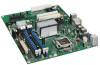
Intel Desktop Board DG33FB Technical Product Specification 1.1.2 Board Layout Figure 1 shows the location of the major components. Figure 1. Major Board Components Table 2 lists the components identified in Figure 1. 12 - Intel BLKDG33FBC | Product Specification - Page 13
x16 connector K Back panel connectors L Processor core power connector (2 X 2) M Rear chassis fan header N LGA775 processor socket O Intel 82G33 GMCH P Processor fan header Q DIMM Channel A sockets R Serial port header S DIMM Channel B sockets T Main Power connector (2 X 12 - Intel BLKDG33FBC | Product Specification - Page 14
Intel Desktop Board DG33FB Technical Product Specification 1.1.3 Block Diagram Figure 2 is a block diagram of the major functional areas. Figure 2. Block Diagram 14 - Intel BLKDG33FBC | Product Specification - Page 15
.htm http://downloadcenter.intel.com http://support.intel.com/support/motherboards/desktop/sb/CS025414.htm 1.4 Processor The board is designed to support the following processors: • Intel Core 2 Quad processor in an LGA775 socket with a 1066 MHz system bus • Intel Core 2 Duo processor in an LGA775 - Intel BLKDG33FBC | Product Specification - Page 16
Intel Desktop Board DG33FB Technical Product Specification 1.5 System Memory The board has four DIMM sockets and supports the following memory features: • 1.8 V GB 4 GB 8 GB For information about... Tested Memory Refer to: http://support.intel.com/support/motherboards/desktop/sb/CS025414.htm 16 - Intel BLKDG33FBC | Product Specification - Page 17
results in multiple zones of dual and single channel operation across the whole of DRAM memory. To use flex mode, it is necessary to populate both channels. For information about... Memory Configuration Examples Refer to: http://support.intel.com/support/motherboards/desktop/sb/CS025414.htm 17 - Intel BLKDG33FBC | Product Specification - Page 18
Intel Desktop Board DG33FB Technical Product Specification Figure 3 illustrates the memory channel and DIMM configuration. NOTE The DIMM 0 sockets of both channels are blue. The DIMM 1 sockets of both channels are black. Figure 3. Memory Channel Configuration and DIMM Configuration # INTEGRATOR'S - Intel BLKDG33FBC | Product Specification - Page 19
. The ICH9DH is a centralized controller for the board's I/O paths. The chipset supports the following features: • Onboard Graphics • Dynamic Video Memory Technology • USB • Serial ATA • Parallel IDE For information about The Intel G33 Express chipset Resources used by the chipset Refer to - Intel BLKDG33FBC | Product Specification - Page 20
memory (as set in the BIOS Setup program) for compatibility drivers allocate additional system memory to the graphics buffer as needed for performing graphics functions. NOTE The use of DVMT requires operating system driver support. 1.6.1.3 Configuration Modes The video modes supported by this board - Intel BLKDG33FBC | Product Specification - Page 21
branding as well as all the features supported by Intel Viiv processor technology, refer to: http://www.intel.com/products/viiv/index.htm 1.6.3 USB The board supports up to 12 USB 2.0 ports, supports UHCI and EHCI, and uses UHCIand EHCI-compatible drivers. The ICH9DH provides the USB controller - Intel BLKDG33FBC | Product Specification - Page 22
Intel Desktop Board DG33FB Technical Product Specification 1.7 Parallel IDE Controller The Parallel ATA IDE controller has one bus-mastering Parallel ATA IDE interface. The Parallel ATA IDE interface supports the following modes: • Programmed I/O (PIO): processor controls data transfer. • 8237- - Intel BLKDG33FBC | Product Specification - Page 23
features: • One serial port header • One parallel port with Extended Capabilities Port (ECP) and Enhanced Parallel Port (EPP) support • Serial IRQ interface compatible with serialized IRQ support the board. The serial port supports data transfers at speeds up to 115.2 kbits/sec with BIOS support. - Intel BLKDG33FBC | Product Specification - Page 24
• Realtek ALC888 audio codec • Back panel audio connectors • Component-side audio headers: ⎯ Intel® High Definition Audio front panel header ⎯ HD audio link header The audio subsystem supports the following features: • A signal-to-noise (S/N) ratio of 95 dB • Independent 5.1 audio playback from back - Intel BLKDG33FBC | Product Specification - Page 25
of the board. The front panel audio header provides mic in and line out signals for the front panel. Microphone bias is supported for both the front and back panel microphone connectors. The front/back panel audio connectors are configurable through the audio device drivers. - Intel BLKDG33FBC | Product Specification - Page 26
The Intel 82566DC Gigabit Ethernet Controller supports the following features: • PCI Express link • 10/100/1000 IEEE 802.3 compliant • Compliant to IEEE 802.3x flow control support • 802.1p and 802.1q • TCP, IP, UDP checksum offload (for IPv4 and IPv6) • Full device driver compatibility • PCI - Intel BLKDG33FBC | Product Specification - Page 27
LAN software and drivers are available from Intel's World Wide Web site. For information about Obtaining LAN software and drivers Refer to Section 5. LAN Connector LED Locations Table 5 describes the LED states when the board is powered up and the LAN subsystem is operating. Table 5. LAN - Intel BLKDG33FBC | Product Specification - Page 28
Intel Desktop Board DG33FB Technical Product Specification 1.12 Hardware Management Subsystem The hardware management features enable the board to be compatible with the Wired for Management (WfM) specification. The board has several hardware management features, including the following: • Fan - Intel BLKDG33FBC | Product Specification - Page 29
sensors and fan headers. Item A B C D E F G Description Auxiliary rear chassis fan Rear chassis fan Thermal diode, located on processor die Thermal diode, located on the GMCH die Processor fan Front chassis fan Thermal diode, located on the ICH9DH die Figure 6. Thermal Sensors and Fan Headers - Intel BLKDG33FBC | Product Specification - Page 30
an operating system that provides full ACPI support. ACPI features include: • Plug and Play (including bus and device enumeration) • Power management control of individual devices, add-in boards (some add-in boards may require an ACPI-aware driver), video displays, and hard disk drives • Methods - Intel BLKDG33FBC | Product Specification - Page 31
lists the power states supported by the board along with the associated power > 30 W G1 - sleeping state S1 - Processor stopped C1 - stop grant G1 - sleeping state G1 Service can be performed safely. Notes: 1. Total system power is dependent on the system configuration, including add-in boards - Intel BLKDG33FBC | Product Specification - Page 32
Intel has worked directly with these two governmental agencies to define the new requirements. Currently Intel Desktop Boards S5 is disabled by default in the BIOS Setup program. Setting this option to support. In addition, software, drivers, and peripherals must fully support ACPI wake events. 32 - Intel BLKDG33FBC | Product Specification - Page 33
on the wake devices supported and manufacturing options. The board provides several power management hardware features, including: • Power ). The computer's response can be set using the Last Power State feature in the BIOS Setup program's Boot menu. For information about The location of the main - Intel BLKDG33FBC | Product Specification - Page 34
are off when the board is off or in the S3, S4, or S5 state. • The processor and Auxiliary fan headers are wired to a fan tachometer input and the Front and Rear fan headers share the tachometer input of the hardware monitoring and fan control device. All fan headers support closed-loop fan - Intel BLKDG33FBC | Product Specification - Page 35
boards that also support this specification can participate in power management and can be used to wake the computer. The use of Instantly Available PC technology requires operating system support and PCI 2.3 compliant add-in cards and drivers in BIOS). 1.13.2.8 WAKE# Signal Wake-up Support When - Intel BLKDG33FBC | Product Specification - Page 36
Intel Desktop Board DG33FB Technical Product Specification 1.13.2.9 +5 V Standby Power Indicator LED The +5 cord before installing or removing any devices connected to the board. Failure to do so could damage the board and any attached devices. Figure 7. Location of the Standby Power Indicator LED - Intel BLKDG33FBC | Product Specification - Page 37
space (256 MB) • GMCH base address registers, internal graphics ranges, PCI Express ports (up to 512 MB) • Memory-mapped I/O that is dynamically allocated for PCI Conventional and PCI Express add-in cards • Intel Management Engine support (6 MB) • Base graphics memory support (1 MB or 8 MB) 37 - Intel BLKDG33FBC | Product Specification - Page 38
Intel Desktop Board DG33FB Technical Product Specification The amount of installed memory that can be used will vary based on add-in cards and BIOS settings. Figure 8 shows a schematic of the system memory map. All installed system memory DOS Compatibility Memory Top of usable DRAM (memory visible - Intel BLKDG33FBC | Product Specification - Page 39
160 KB 1 KB 127 KB 512 KB Description Extended memory Runtime BIOS Reserved Potential available high DOS memory (open to the PCI bus). Dependent on video adapter used. Video memory and BIOS Extended BIOS data (movable by memory manager software) Extended conventional memory Conventional memory 39 - Intel BLKDG33FBC | Product Specification - Page 40
Intel Desktop Board DG33FB Technical Product Specification 2.2 Connectors and Headers CAUTION cable. Use shielded cable that meets the requirements for full-speed devices. This section describes the board's connectors and headers. The connectors and headers can be divided into these groups: • Back - Intel BLKDG33FBC | Product Specification - Page 41
Technical Reference 2.2.1 Back Panel Connectors Figure 9 shows the locations of the back panel connectors. Item A B C D E F G H I J K Description PS/2 mouse port PS/2 keyboard port VGA port IEEE 1394a port USB ports [2] USB ports [2] LAN USB ports [2] Line in Mic in Line out Figure 9. Back Panel - Intel BLKDG33FBC | Product Specification - Page 42
Intel Desktop Board DG33FB Technical Product Specification 2.2.2 Component-side Connectors and Headers Figure 10 shows the locations of the component-side connectors and headers. Figure 10. Component-side Connectors and Headers 42 - Intel BLKDG33FBC | Product Specification - Page 43
G PCI Conventional bus add-in card connector H PCI Express x1 connector I PCI Express x16 connector J Processor core power connector (2 X 2) K Rear chassis fan header L Processor fan header M Serial port header N Main power connector (2 X 12) O Diskette drive connector P Chassis - Intel BLKDG33FBC | Product Specification - Page 44
Intel Desktop Board DG33FB Technical Product Specification 2.2.2.1 Signal Tables for the Connectors and Headers Table 11. Rear Chassis Fan Headers Pin Signal Name 1 Control 2 +12 V 3 Tach Table 15. Processor Fan Header Pin Signal Name 1 Ground 2 +12 V 3 FAN_TACH 4 FAN_CONTROL 44 - Intel BLKDG33FBC | Product Specification - Page 45
bus master capable. • SMBus signals are routed to all PCI Conventional bus connectors. This enables PCI Conventional bus add-in boards with SMBus support to access sensor data on the board. The specific SMBus signals are as follows: ⎯ The SMBus clock line is connected to pin A40. ⎯ The SMBus data - Intel BLKDG33FBC | Product Specification - Page 46
12 connector. This connector is compatible with 2 x 10 connectors previously used on Intel Desktop boards. The board supports the use of ATX12V power supplies be used. Failure to do so will prevent the board from booting. Table 18. Processor Core Power Connector Pin Signal Name Pin Signal Name 1 - Intel BLKDG33FBC | Product Specification - Page 47
Technical Reference 2.2.2.5 Front Panel Header This section describes the functions of the front panel header. Table 20 lists the signal names of the front panel header. Figure 11 is a connection diagram for the front panel header. Table 20. Front Panel Header In/ Pin Signal Out Description - Intel BLKDG33FBC | Product Specification - Page 48
Intel Desktop Board DG33FB Technical Product Specification 2.2.2.5.2 Reset Switch Header Pins 5 and 7 can be connected to a momentary single pole, single throw (SPST) type switch that is normally open. When the switch is closed, the board resets and runs the POST. 2.2.2.5.3 Power/Sleep LED - Intel BLKDG33FBC | Product Specification - Page 49
Technical Reference 2.2.2.7 Front Panel USB Headers Figure 12 is a connection diagram for the front panel USB headers. # INTEGRATOR'S NOTES • The +5 V DC power on the front panel USB headers is fused. • Use only a front panel USB connector that conforms to the USB 2.0 specification for high-speed - Intel BLKDG33FBC | Product Specification - Page 50
settings for the three modes: normal, configure, and recovery. When the jumper is set to configure mode and the computer is powered-up, the BIOS compares the processor version and the microcode version in the BIOS and reports if the two match. Figure 13. Location of the Jumper Block Table 24 - Intel BLKDG33FBC | Product Specification - Page 51
Technical Reference 2.4 Mechanical Considerations 2.4.1 Form Factor The board is designed to fit into an ATX-form-factor chassis. Figure 14 illustrates the mechanical form factor of the board. Dimensions are given in inches [millimeters]. The outer dimensions are 11.60 inches by 9.60 inches [292 - Intel BLKDG33FBC | Product Specification - Page 52
supported 65 W processor (see Section 1.4 on page 15 for a list of supported processors), 1 GB DDR2 RAM, one hard disk drive, one optical drive, and all board information about Selecting an appropriate power supply Refer to http://support.intel.com/support/motherboards/desktop/s b/CS-026472.htm 52 - Intel BLKDG33FBC | Product Specification - Page 53
the fan headers. Table 26. Fan Header Current Capability Fan Header Maximum Available Current Processor fan Front chassis fan Rear chassis fan Auxiliary fan 2.0 A 1.5 A 1.5 A 2.0 A 2.5.3 Add-in Board Considerations The board is designed to provide 2 A (average) of +5 V current for each add-in - Intel BLKDG33FBC | Product Specification - Page 54
in reduced performance of both the processor and/or voltage regulator or, in some instances, damage to the board. For a list of chassis that have been tested with Intel desktop boards please refer to the following website: http://developer.intel.com/design/motherbd/cooling.htm All responsibility - Intel BLKDG33FBC | Product Specification - Page 55
Technical Reference Figure 15 shows the locations of the localized high temperature zones. Item A B C D Description Processor voltage regulator area Processor Intel 82G33 GMCH Intel 82801IH (ICH9DH) Figure 15. Localized High Temperature Zones 55 - Intel BLKDG33FBC | Product Specification - Page 56
considering proper airflow to cool the board. Table 27. Thermal Considerations for Components Component Maximum Case Temperature Processor For processor case temperature, see processor datasheets and processor specification updates Intel 82G33 GMCH Intel 82801IH (ICH9DH) 97 oC (under bias - Intel BLKDG33FBC | Product Specification - Page 57
Technical Reference 2.8 Environmental Table 28 lists the environmental specifications for the board. Table 28. Desktop Board DG33FB Environmental Specifications Parameter Specification Temperature Non-Operating Operating -40 °C to +70 °C 0 °C to +55 °C Shock Unpackaged 50 g trapezoidal - Intel BLKDG33FBC | Product Specification - Page 58
Intel Desktop Board DG33FB Technical Product Specification 58 - Intel BLKDG33FBC | Product Specification - Page 59
(SMBIOS 61 3.5 Legacy USB Support 62 3.6 BIOS Updates 63 3.7 BIOS Recovery 64 3.8 Boot Options 65 3.9 Adjusting Boot Speed 66 3.10 BIOS Security Features 67 3.1 Introduction The board uses an Intel BIOS that is stored in the Serial Peripheral Interface Flash Memory (SPI Flash) and can be - Intel BLKDG33FBC | Product Specification - Page 60
Intel Desktop Board DG33FB Technical Product Specification Table 29 lists the BIOS Setup program menu features. Table 29. BIOS Setup Program Menu Bar Maintenance Main Advanced Security Clears passwords and displays processor information Displays processor and memory configuration Configures - Intel BLKDG33FBC | Product Specification - Page 61
auto-configuration options by specifying manual configuration in the BIOS Setup program. To use ATA-66/100/133 features the following items are required: • An ATA-66/100/133 peripheral device • An ATA-66/100/133 compatible cable • ATA-66/100/133 operating system device drivers NOTE Do not connect an - Intel BLKDG33FBC | Product Specification - Page 62
BIOS is no longer used. 7. Additional USB legacy feature options can be access by using Intel Integrator Toolkit. To install an operating system that supports USB, verify that Legacy USB support in the BIOS Setup program is set to Enabled and follow the operating system's installation instructions - Intel BLKDG33FBC | Product Specification - Page 63
an incompatible BIOS. NOTE Review the instructions distributed with the upgrade utility before attempting a BIOS update. For information about BIOS update utilities Refer to http://support.intel.com/support/motherboards/desktop/s b/CS-022312.htm 3.6.1 Language Support The BIOS Setup program - Intel BLKDG33FBC | Product Specification - Page 64
diskette) No USB hard disk drive No Legacy diskette drive (with a 1.44 MB diskette) connected to the No legacy diskette drive interface For information about BIOS recovery Refer to http://support.intel.com/support/motherboards/desktop 64 - Intel BLKDG33FBC | Product Specification - Page 65
Overview of BIOS Features 3.8 Boot Options In the BIOS Setup program, the user can choose to boot from a 3.8.1 CD-ROM Boot Booting from CD-ROM is supported in compliance to the El Torito bootable CD-ROM format specification. Under the Boot menu in the BIOS Setup program, ATAPI CDROM is listed as a - Intel BLKDG33FBC | Product Specification - Page 66
Intel Desktop Board DG33FB Technical Product Specification 3.9 Adjusting Boot Speed These factors affect system boot speed: • Selecting and configuring peripherals properly • Optimized BIOS -in adapter features, such as logo displays, screen repaints, or mode changes in POST. These features may add - Intel BLKDG33FBC | Product Specification - Page 67
Overview of BIOS Features 3.10 BIOS Security Features The BIOS includes security features that restrict access to the BIOS Setup program and who can boot the computer. A supervisor password and a user password can be set for the BIOS Setup program and for booting the computer, with the following - Intel BLKDG33FBC | Product Specification - Page 68
Intel Desktop Board DG33FB Technical Product Specification 68 - Intel BLKDG33FBC | Product Specification - Page 69
4.2 BIOS Beep Codes 69 4.3 BIOS Error Messages 69 4.4 Port 80h POST Codes 70 4.1 Speaker The board-mounted BIOS Beep Codes Whenever a recoverable error occurs during POST, the BIOS displays an error message describing the problem (see Table 34). Table 34. Beep Codes Type Pattern Memory - Intel BLKDG33FBC | Product Specification - Page 70
Intel Desktop Board DG33FB Technical Product Specification 4.4 Port 80h POST Codes During the POST, the BIOS generates diagnostic by any PEIM/driver for debug. Host Processors: 1F is an unrecoverable CPU error. 20 - 2F Memory/Chipset: 2F is no memory detected or no useful memory detected. 30 - - Intel BLKDG33FBC | Product Specification - Page 71
host processor (Boot Strap Processor) 11 Host processor Cache initialization (including APs) 12 Starting Application processor initialization 13 SMM initialization Chipset 21 Initializing a chipset component Memory 22 Reading SPD from memory DIMMs 23 Detecting presence of memory DIMMs - Intel BLKDG33FBC | Product Specification - Page 72
Intel Desktop Board DG33FB Core E0 Started dispatching PEIMs (emitted on first report of EFI_SW_PC_INIT_BEGIN EFI_SW_PEI_PC_HANDOFF_TO_NEXT) E2 Permanent memory found E1, E3 Reserved for PEI/PEIMs DXE Core E4 Entered DXE phase E5 Started dispatching drivers E6 Started connecting drivers - Intel BLKDG33FBC | Product Specification - Page 73
Code Description of POST Operation DXE Drivers E7 Waiting for user input E8 Checking password E9 Entering BIOS setup EB Calling Legacy Option service ExitBootServices ( ) has been called F9 EFI runtime service SetVirtualAddressMap ( ) has been called FA EFI runtime service ResetSystem - Intel BLKDG33FBC | Product Specification - Page 74
Intel Desktop Board DG33FB Technical Product Specification Table 38. Typical Port 80h POST Sequence POST Code Description 21 Initializing a chipset component 22 Reading SPD from memory DIMMs 23 Detecting presence of memory DIMMs 25 Configuring memory 28 Testing memory 34 Loading - Intel BLKDG33FBC | Product Specification - Page 75
: • Safety standards • European Union Declaration of Conformity statement • Product Ecology statements • Electromagnetic Compatibility (EMC) standards • Product certification markings 5.1.1 Safety Standards Desktop Board DG33FB complies with the safety standards stated in Table 39 when correctly - Intel BLKDG33FBC | Product Specification - Page 76
DG33FB Technical Product Specification 5.1.2 European Union Declaration of Conformity Statement We, Intel Corporation, declare under our sole responsibility that the product Intel® Desktop Board DG33FB is in conformity with all applicable essential requirements necessary for CE marking, following - Intel BLKDG33FBC | Product Specification - Page 77
Regulatory Compliance and Battery Disposal Information Polski Niniejszy produkt jest zgodny z postanowieniami Dyrektyw Unii Europejskiej 2004/108/EC i 73/23/EWG. Portuguese Este produto cumpre com as normas da Diretiva Européia 2004/108/EC & 2006/95/EC. Español Este producto cumple con las normas - Intel BLKDG33FBC | Product Specification - Page 78
of this program, including the scope of covered products, available locations, shipping instructions, terms and conditions, etc Intel Product Recycling Program http://www.intel.com/intel/other/ehs/product_ecology Deutsch Als Teil von Intels Engagement für den Umweltschutz hat das Unternehmen das - Intel BLKDG33FBC | Product Specification - Page 79
pour en savoir plus sur ce programme, à savoir les produits concernés, les adresses disponibles, les instructions d'expédition, les conditions générales, etc http://www.intel.com/intel /other/ehs/product_ecology Malay Sebagai sebahagian daripada komitmennya terhadap tanggungjawab persekitaran - Intel BLKDG33FBC | Product Specification - Page 80
kayıtlar ve şartlar v.s dahil bütün ayrıntılarını ögrenmek için lütfen http://www.intel.com/intel/other/ehs/product_ecology Web sayfasına gidin. 5.1.3.3 Lead Free Desktop Board This Desktop Board is a European Union Restriction of Hazardous Substances (EU RoHS Directive 2002/95/EC) compliant product - Intel BLKDG33FBC | Product Specification - Page 81
40 shows the various forms of the "Lead-Free 2nd Level Interconnect" mark as it appears on the board and accompanying collateral. Table 40. Lead-Free Board Markings Description Mark Lead-Free 2nd Level Interconnect: This symbol is used to identify electrical and electronic assemblies and - Intel BLKDG33FBC | Product Specification - Page 82
Intel Desktop Board DG33FB Technical Product Specification 5.1.4 EMC Regulations Desktop Board DG33FB complies with the EMC regulations stated in Table 41 when correctly installed in a compatible host system. Table 41. EMC Regulations Regulation Title FCC 47 CFR Part 15, Subpart B Title 47 of - Intel BLKDG33FBC | Product Specification - Page 83
near a radio or television receiver in a domestic environment, it may cause radio interference. Install and use the equipment according to the instruction manual. Korean Class B statement translation: this is household equipment that is certified to comply with EMC requirements. You may use this - Intel BLKDG33FBC | Product Specification - Page 84
UL joint US/Canada Recognized Component mark. Includes adjacent UL file number for Intel desktop boards: E210882. support.intel.com/support/motherboards/desktop/ Taiwan BSMI (Bureau of Standards, Metrology and Inspections) mark. Includes adjacent Intel company number, D33025. Printed wiring board - Intel BLKDG33FBC | Product Specification - Page 85
Regulatory Compliance and Battery Disposal Information 5.2 Battery Disposal Information CAUTION Risk of explosion if the battery is replaced with an incorrect type. Batteries should be recycled where possible. Disposal of used batteries must be in accordance with local environmental regulations. - Intel BLKDG33FBC | Product Specification - Page 86
Intel Desktop Board DG33FB Technical Product Specification PRECAUCIÓN Existe peligro de explosión si la pila no se cambia de forma adecuada. Utilice solamente pilas iguales o del mismo tipo - Intel BLKDG33FBC | Product Specification - Page 87
Regulatory Compliance and Battery Disposal Information AWAS Risiko letupan wujud jika bateri digantikan dengan jenis yang tidak betul. Bateri sepatutnya dikitar semula jika boleh. Pelupusan bateri terpakai mestilah mematuhi peraturan alam sekitar tempatan. OSTRZEŻENIE Istnieje niebezpieczeństwo - Intel BLKDG33FBC | Product Specification - Page 88
Intel Desktop Board DG33FB Technical Product Specification 88
-
 1
1 -
 2
2 -
 3
3 -
 4
4 -
 5
5 -
 6
6 -
 7
7 -
8
-
9
-
10
-
11
-
12
-
13
-
14
-
15
-
16
-
17
-
18
-
19
-
20
-
21
-
22
-
23
-
24
-
25
-
26
-
27
-
28
-
29
-
30
-
31
-
32
-
33
-
34
-
35
-
36
-
37
-
38
-
39
-
40
-
41
-
42
-
43
-
44
-
45
-
46
-
47
-
48
-
49
-
50
-
51
-
52
-
53
-
54
-
55
-
56
-
57
-
58
-
59
-
60
-
61
-
62
-
63
-
64
-
65
-
66
-
67
-
68
-
69
-
70
-
71
-
72
-
73
-
74
-
75
-
76
-
77
-
78
-
79
-
80
-
81
-
82
-
83
-
84
-
85
-
86
-
87
-
88
 |
 |

May 2007
Order Number:
D88105-001US
The Intel
®
Desktop Board DG33FB may contain design defects or errors known as errata that may cause the product to deviate from published specifications.
Current
characterized errata are documented in the Intel Desktop Board DG33FB Specification Update.
Intel® Desktop Board
DG33FB
Technical Product Specification