Intel BLKDX58OG Product Specification - Page 14
Table 3., Components Shown
 |
View all Intel BLKDX58OG manuals
Add to My Manuals
Save this manual to your list of manuals |
Page 14 highlights
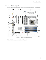
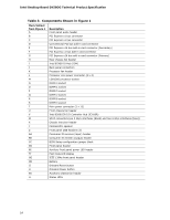
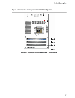
Intel Desktop Board DX58OG Technical Product Specification Table 3. Components Shown in Figure 1 Item/callout from Figure 1 A B C D E F G H I J K L M N O P Q R S T U V W X Y Z AA BB CC DD EE FF GG HH II JJ KK LL Description Front panel audio header PCI Express x1 bus connector PCI Express x1 bus connector Conventional PCI bus add-in card connector PCI Express x16 bus add-in card connector (Secondary) PCI Express x1 bus add-in card connector PCI Express x16 bus add-in card connector (Primary) Rear chassis fan header Intel 82X58 IO Hub (IOH) Back panel connectors Processor fan header Processor core power connector (2 x 4) LGA1366 processor socket DIMM 4 socket DIMM 1 socket DIMM 5 socket DIMM 2 socket DIMM 6 socket DIMM 3 socket Main power connector (2 x 12) Front chassis fan header Intel 82801IJR I/O Controller Hub (ICH10R) SATA connectors (six 3 Gb/s interfaces (black) and two 6 Gb/s interfaces (blue)) Chassis intrusion header Piezoelectric speaker Front panel USB headers (3) Consumer IR receiver (input) header Consumer IR emitter (output) header BIOS Setup configuration jumper block Front panel header Auxiliary front panel power LED header Post Code LED display IEEE 1394a front panel header Battery Onboard Reset button Onboard Power button Auxilliary chassis fan header Status LEDs 14
-
 1
1 -
2
-
3
-
4
-
5
-
6
-
7
-
8
-
 9
9 -
 10
10 -
 11
11 -
 12
12 -
 13
13 -
 14
14 -
 15
15 -
 16
16 -
 17
17 -
 18
18 -
 19
19 -
20
-
21
-
22
-
23
-
24
-
25
-
26
-
27
-
28
-
29
-
30
-
31
-
32
-
33
-
34
-
35
-
36
-
37
-
38
-
39
-
40
-
41
-
42
-
43
-
44
-
45
-
46
-
47
-
48
-
49
-
50
-
51
-
52
-
53
-
54
-
55
-
56
-
57
-
58
-
59
-
60
-
61
-
62
-
63
-
64
-
65
-
66
-
67
-
68
-
69
-
70
-
71
-
72
-
73
-
74
-
75
-
76
-
77
-
78
-
79
-
80
-
81
-
82
-
83
-
84
-
85
-
86
-
87
-
88
-
89
-
90
-
91
 |
 |