Intel BLKDX58OG Product Specification - Page 18
Memory Configurations
 |
View all Intel BLKDX58OG manuals
Add to My Manuals
Save this manual to your list of manuals |
Page 18 highlights
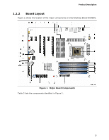
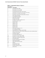
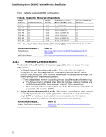
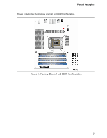
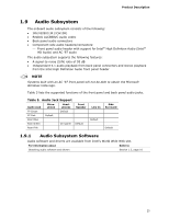
Intel Desktop Board DX58OG Technical Product Specification Table 4 lists the supported DIMM configurations. Table 4. Supported Memory Configurations DIMM Capacity 512 MB Configuration (Note) SS SDRAM Density 1 Gbit SDRAM Organization Front-side/Back-side 64 M x16/empty Number of SDRAM Devices 4 1024 MB SS 1 Gbit 128 M x8/empty 8 1024 MB SS 2048 MB DS 2048 MB SS 2 Gbit 128 M x16/empty 4 1 Gbit 128 M x8/128 M x8 16 2 Gbit 128 M x16/empty 8 4096 MB DS 2 Gbit 256 M x8/256 M x8 16 8192 MB DS 4 Gbit 512 M x8/512 M x8 16 Note: "DS" refers to double-sided memory modules (containing two rows of SDRAM) and "SS" refers to single-sided memory modules (containing one row of SDRAM). For information about... Tested Memory XMP Tested Memory Refer to: http://www.intel.com/support/motherboards/desktop/sb/CS025414.htm http://www.intel.com/personal/gaming/extremememory.htm 1.5.1 Memory Configurations The Intel Core i7 and Intel Xeon Processors support the following types of memory organization: • Tri/Dual channel (Interleaved) mode. This mode offers the highest throughput for real world applications. Interleaving reduces overall memory latency by accessing the DIMM memory sequentially. Data is spread amongst the memory modules in an alternating pattern. ⎯ Three independent memory channels give two possible modes of interleaving: • Tri-channel mode is enabled when identical matched memory modules are installed in each of the three memory channels (blue connectors). • Dual channel mode is enabled when two of the blue memory connectors are populated with matched DIMMs. • Single channel (Asymmetric) mode. This mode is equivalent to single channel bandwidth operation for real world applications. This mode is used when only a single DIMM is installed or the installed memory modules are not matched. Technology and device width can vary from one channel to the other. For information about... Memory Configuration Examples Refer to: http://www.intel.com/support/motherboards/desktop/sb/cs011965.htm 18
-
 1
1 -
2
-
3
-
4
-
5
-
6
-
7
-
8
-
9
-
10
-
11
-
12
-
 13
13 -
 14
14 -
 15
15 -
 16
16 -
 17
17 -
 18
18 -
 19
19 -
 20
20 -
 21
21 -
 22
22 -
 23
23 -
24
-
25
-
26
-
27
-
28
-
29
-
30
-
31
-
32
-
33
-
34
-
35
-
36
-
37
-
38
-
39
-
40
-
41
-
42
-
43
-
44
-
45
-
46
-
47
-
48
-
49
-
50
-
51
-
52
-
53
-
54
-
55
-
56
-
57
-
58
-
59
-
60
-
61
-
62
-
63
-
64
-
65
-
66
-
67
-
68
-
69
-
70
-
71
-
72
-
73
-
74
-
75
-
76
-
77
-
78
-
79
-
80
-
81
-
82
-
83
-
84
-
85
-
86
-
87
-
88
-
89
-
90
-
91
 |
 |