Intel BLKDX58OG Product Specification - Page 26
LAN Subsystem Software, RJ-45 LAN Connector with Integrated LEDs
 |
View all Intel BLKDX58OG manuals
Add to My Manuals
Save this manual to your list of manuals |
Page 26 highlights
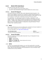
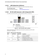
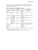
Intel Desktop Board DX58OG Technical Product Specification 1.10.2 LAN Subsystem Software LAN software and drivers are available from Intel's World Wide Web site. For information about Obtaining LAN software and drivers Refer to http://downloadcenter.intel.com 1.10.3 RJ-45 LAN Connector with Integrated LEDs Two LEDs are built into the RJ-45 LAN connector (shown in Figure 5). Item A B Description Link LED (Green) Data Rate LED (Green/Yellow) Figure 5. LAN Connector LED Locations Table 6 describes the LED states when the board is powered up and the LAN subsystem is operating. Table 6. LAN Connector LED States LED LED Color LED State Off Link Green On Blinking Off Data Rate Green/Yellow Green Yellow Condition LAN link is not established. LAN link is established. LAN activity is occurring 10 Mbits/sec data rate is selected. 100 Mbits/sec data rate is selected. 1000 Mbits/sec data rate is selected. 26
-
 1
1 -
2
-
3
-
4
-
5
-
6
-
7
-
8
-
9
-
10
-
11
-
12
-
13
-
14
-
15
-
16
-
17
-
18
-
19
-
20
-
 21
21 -
 22
22 -
 23
23 -
 24
24 -
 25
25 -
 26
26 -
 27
27 -
 28
28 -
 29
29 -
 30
30 -
 31
31 -
32
-
33
-
34
-
35
-
36
-
37
-
38
-
39
-
40
-
41
-
42
-
43
-
44
-
45
-
46
-
47
-
48
-
49
-
50
-
51
-
52
-
53
-
54
-
55
-
56
-
57
-
58
-
59
-
60
-
61
-
62
-
63
-
64
-
65
-
66
-
67
-
68
-
69
-
70
-
71
-
72
-
73
-
74
-
75
-
76
-
77
-
78
-
79
-
80
-
81
-
82
-
83
-
84
-
85
-
86
-
87
-
88
-
89
-
90
-
91
 |
 |