Intel BLKDX58OG Product Specification - Page 36
Status LED Indicators, CAUTION
 |
View all Intel BLKDX58OG manuals
Add to My Manuals
Save this manual to your list of manuals |
Page 36 highlights
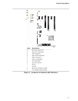
Intel Desktop Board DX58OG Technical Product Specification 1.12.2.9 Status LED Indicators The status LEDs display various status indicators as defined below. Figure 7 shows the location of the LED indicators. • The +5 V standby power indicator LED shows that power is still present even when the computer appears to be off. • The hard drive activity LED indicates activity of hard drives connected to the IOH and any external discrete controllers on the board. • The CPU Hot and VR Hot LEDs are controlled by external circuitry. • The Watch Dog Fire/Back to BIOS LED indicates when the watch dog timer fires to reset the board. The BIOS will program this LED to flash as early as possible in the post. If the Back to BIOS button has been pressed, the BIOS will program this LED to be constantly on. • The six initialization LEDs will flash when initialization activity starts and stay on when initialization is complete. • The operating system LED changes to "constant on" just before the BIOS hands off control to the operating system (int 19). CAUTION If AC power has been switched off and the standby power indicator is still lit, disconnect the power cord before installing or removing any devices connected to the board. Failure to do so could damage the board and any attached devices. 36
-
 1
1 -
2
-
3
-
4
-
5
-
6
-
7
-
8
-
9
-
10
-
11
-
12
-
13
-
14
-
15
-
16
-
17
-
18
-
19
-
20
-
21
-
22
-
23
-
24
-
25
-
26
-
27
-
28
-
29
-
30
-
 31
31 -
 32
32 -
 33
33 -
 34
34 -
 35
35 -
 36
36 -
 37
37 -
 38
38 -
 39
39 -
 40
40 -
 41
41 -
42
-
43
-
44
-
45
-
46
-
47
-
48
-
49
-
50
-
51
-
52
-
53
-
54
-
55
-
56
-
57
-
58
-
59
-
60
-
61
-
62
-
63
-
64
-
65
-
66
-
67
-
68
-
69
-
70
-
71
-
72
-
73
-
74
-
75
-
76
-
77
-
78
-
79
-
80
-
81
-
82
-
83
-
84
-
85
-
86
-
87
-
88
-
89
-
90
-
91
 |
 |