Intel BLKDX58OG Product Specification - Page 45
Signal Tables for the Connectors and Headers
 |
View all Intel BLKDX58OG manuals
Add to My Manuals
Save this manual to your list of manuals |
Page 45 highlights
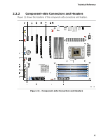
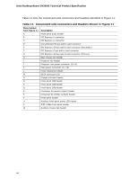
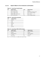
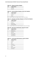
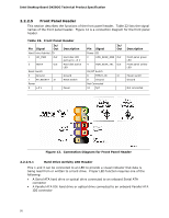
Technical Reference 2.2.2.1 Signal Tables for the Connectors and Headers Table 12. Front Panel Audio Header Pin Signal Name Pin 1 [Port 2] Left channel 2 3 [Port 2] Right channel 4 5 [Port 1] Right channel 6 7 SENSE_SEND (Jack detection) 8 9 [Port 2] Left channel 10 Signal Name Ground PRESENCE# (Dongle present) [Port 1] SENSE_RETURN Key (no pin) [Port 2] SENSE_RETURN Table 13. Serial ATA Connectors Pin Signal Name 1 Ground 2 TXP 3 TXN 4 Ground 5 RXN 6 RXP 7 Ground Table 14. Front Panel IEEE 1394a Header Pin Signal Name Pin 1 Data A (positive) 2 3 Ground 4 5 Data B (positive) 6 7 +12V_DC 8 9 Key (no pin) 10 Note: The +12 V DC power on the IEEE 1394a header is fused. Signal Name Data A (negative) Ground Data B (negative) +12 V_DC Ground 45
-
 1
1 -
2
-
3
-
4
-
5
-
6
-
7
-
8
-
9
-
10
-
11
-
12
-
13
-
14
-
15
-
16
-
17
-
18
-
19
-
20
-
21
-
22
-
23
-
24
-
25
-
26
-
27
-
28
-
29
-
30
-
31
-
32
-
33
-
34
-
35
-
36
-
37
-
38
-
39
-
 40
40 -
 41
41 -
 42
42 -
 43
43 -
 44
44 -
 45
45 -
 46
46 -
 47
47 -
 48
48 -
 49
49 -
 50
50 -
51
-
52
-
53
-
54
-
55
-
56
-
57
-
58
-
59
-
60
-
61
-
62
-
63
-
64
-
65
-
66
-
67
-
68
-
69
-
70
-
71
-
72
-
73
-
74
-
75
-
76
-
77
-
78
-
79
-
80
-
81
-
82
-
83
-
84
-
85
-
86
-
87
-
88
-
89
-
90
-
91
 |
 |
Technical Reference
45
2.2.2.1
Signal Tables for the Connectors and Headers
Table 12.
Front Panel Audio Header
Pin
Signal Name
Pin
Signal Name
1
[Port 2] Left channel
2
Ground
3
[Port 2] Right channel
4
PRESENCE# (Dongle present)
5
[Port 1] Right channel
6
[Port 1] SENSE_RETURN
7
SENSE_SEND (Jack detection)
8
Key (no pin)
9
[Port 2] Left channel
10
[Port 2] SENSE_RETURN
Table 13.
Serial ATA Connectors
Pin
Signal Name
1
Ground
2
TXP
3
TXN
4
Ground
5
RXN
6
RXP
7
Ground
Table 14.
Front Panel IEEE 1394a Header
Pin
Signal Name
Pin
Signal Name
1
Data A (positive)
2
Data A (negative)
3
Ground
4
Ground
5
Data B (positive)
6
Data B (negative)
7
+12V_DC
8
+12 V_DC
9
Key (no pin)
10
Ground
Note:
The +12 V DC power on the IEEE 1394a header is fused.