Intel BLKDX58OG Product Specification - Page 48
Power Supply Connectors
 |
View all Intel BLKDX58OG manuals
Add to My Manuals
Save this manual to your list of manuals |
Page 48 highlights
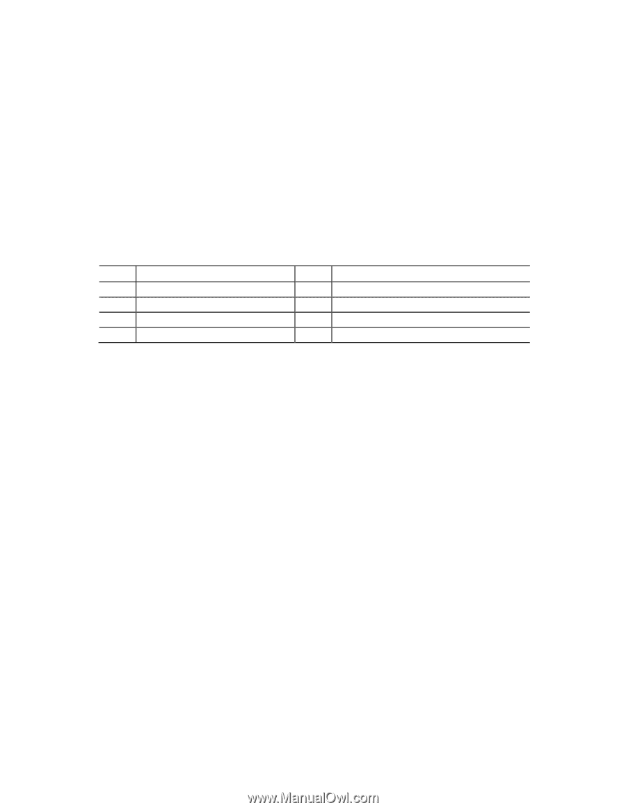
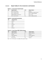
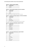
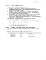
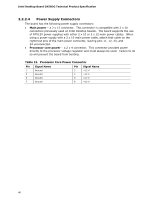
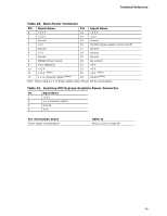
Intel Desktop Board DX58OG Technical Product Specification 2.2.2.4 Power Supply Connectors The board has the following power supply connectors: • Main power - a 2 x 12 connector. This connector is compatible with 2 x 10 connectors previously used on Intel Desktop boards. The board supports the use of ATX12V power supplies with either 2 x 10 or 2 x 12 main power cables. When using a power supply with a 2 x 10 main power cable, attach that cable on the rightmost pins of the main power connector, leaving pins 11, 12, 23, and 24 unconnected. • Processor core power - a 2 x 4 connector. This connector provides power directly to the processor voltage regulator and must always be used. Failure to do so will prevent the board from booting. Table 19. Processor Core Power Connector Pin Signal Name Pin Signal Name 1 Ground 3 Ground 5 Ground 7 Ground 2 +12 V 4 +12 V 6 +12 V 8 +12 V 48
-
 1
1 -
2
-
3
-
4
-
5
-
6
-
7
-
8
-
9
-
10
-
11
-
12
-
13
-
14
-
15
-
16
-
17
-
18
-
19
-
20
-
21
-
22
-
23
-
24
-
25
-
26
-
27
-
28
-
29
-
30
-
31
-
32
-
33
-
34
-
35
-
36
-
37
-
38
-
39
-
40
-
41
-
42
-
 43
43 -
 44
44 -
 45
45 -
 46
46 -
 47
47 -
 48
48 -
 49
49 -
 50
50 -
 51
51 -
 52
52 -
 53
53 -
54
-
55
-
56
-
57
-
58
-
59
-
60
-
61
-
62
-
63
-
64
-
65
-
66
-
67
-
68
-
69
-
70
-
71
-
72
-
73
-
74
-
75
-
76
-
77
-
78
-
79
-
80
-
81
-
82
-
83
-
84
-
85
-
86
-
87
-
88
-
89
-
90
-
91
 |
 |