Intel BLKDX58OG Product Specification - Page 50
Front Panel Header
 |
View all Intel BLKDX58OG manuals
Add to My Manuals
Save this manual to your list of manuals |
Page 50 highlights
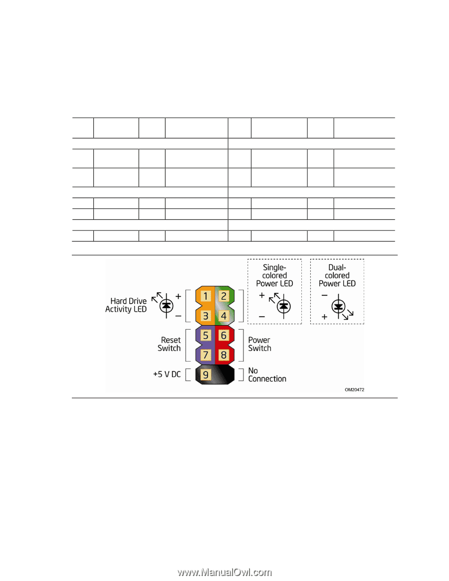
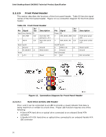
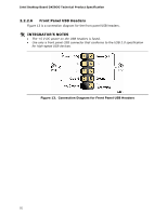
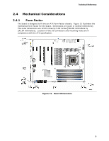
Intel Desktop Board DX58OG Technical Product Specification 2.2.2.5 Front Panel Header This section describes the functions of the front panel header. Table 22 lists the signal names of the front panel header. Figure 12 is a connection diagram for the front panel header. Table 22. Front Panel Header Pin Signal In/ Out Description Hard Drive Activity LED 1 HD_PWR Out Hard disk LED pull-up to +5 V 3 HDA# Out Hard disk active LED Reset Switch 5 Ground Ground 7 FP_RESET# In Power Reset switch 9 +5 V Power Pin Signal In/ Out Power LED 2 HDR_BLNK_GRN Out 4 HDR_BLNK_YEL Out On/Off Switch 6 FPBUT_IN In 8 Ground Not Connected 10 N/C Description Front panel green LED Front panel yellow LED Power switch Ground Not connected Figure 12. Connection Diagram for Front Panel Header 2.2.2.5.1 Hard Drive Activity LED Header Pins 1 and 3 can be connected to an LED to provide a visual indicator that data is being read from or written to a hard drive. Proper LED function requires one of the following: • A Serial ATA hard drive or optical drive connected to an onboard Serial ATA connector • A Parallel ATA IDE hard drive or optical drive connected to an onboard Parallel ATA IDE connector 50
-
 1
1 -
2
-
3
-
4
-
5
-
6
-
7
-
8
-
9
-
10
-
11
-
12
-
13
-
14
-
15
-
16
-
17
-
18
-
19
-
20
-
21
-
22
-
23
-
24
-
25
-
26
-
27
-
28
-
29
-
30
-
31
-
32
-
33
-
34
-
35
-
36
-
37
-
38
-
39
-
40
-
41
-
42
-
43
-
44
-
 45
45 -
 46
46 -
 47
47 -
 48
48 -
 49
49 -
 50
50 -
 51
51 -
 52
52 -
 53
53 -
 54
54 -
 55
55 -
56
-
57
-
58
-
59
-
60
-
61
-
62
-
63
-
64
-
65
-
66
-
67
-
68
-
69
-
70
-
71
-
72
-
73
-
74
-
75
-
76
-
77
-
78
-
79
-
80
-
81
-
82
-
83
-
84
-
85
-
86
-
87
-
88
-
89
-
90
-
91
 |
 |