Intel BOXD845GLLY Product Guide
Intel BOXD845GLLY - 845gl Pga478 Max-2GB Sdr Matx4pci Vid Snd Ata100 400mhz Manual
 |
UPC - 735858153324
View all Intel BOXD845GLLY manuals
Add to My Manuals
Save this manual to your list of manuals |
Intel BOXD845GLLY manual content summary:
- Intel BOXD845GLLY | Product Guide - Page 1
Intel® Desktop Boards D845GLLY and D845GLAD Product Guide Order Number: A84618-001 - Intel BOXD845GLLY | Product Guide - Page 2
Intel® Desktop Boards D845GLLY and D845GLAD Product Guide. Date April 2002 If an FCC declaration of conformity marking is present on the board the instructions, may Intel may make changes to specifications and product descriptions at any time, without notice. The Desktop Boards D845GLLY and D845GLAD - Intel BOXD845GLLY | Product Guide - Page 3
Desktop Board Features Desktop Board Components 9 Processor ...10 Main Memory ...11 Intel® 845GL Chipset...11 Intel® 82845GL Graphics and Memory Controller Hub (GMCH 12 Intel® 82801DB I/O Controller Hub (ICH4 12 Firmware Hub (FWH 12 Input/Output (I/O) Controller 12 Integrated Graphics...13 LAN - Intel BOXD845GLLY | Product Guide - Page 4
Intel Desktop Boards D845GLLY and D845GLAD Product Guide Installing and Removing Memory 23 Installing DIMMs ...24 Removing DIMMs ...24 Connecting the IDE Cable 25 Connecting the Front Panel Header 26 Setting the Jumper Blocks 26 Setting the BIOS Configuration Jumper Block 26 Setting the Front - Intel BOXD845GLLY | Product Guide - Page 5
Back Panel Connectors 60 Midboard Connectors 61 Audio Connectors 61 Power and Hardware Connectors 62 Add-In Card and Peripheral Interface Connectors 63 Front Panel Headers 64 Desktop Board Resources 66 Memory Map ...66 DMA Channels ...66 Interrupts ...67 A Error Messages and Indicators BIOS - Intel BOXD845GLLY | Product Guide - Page 6
Intel Desktop Boards D845GLLY and D845GLAD Product Guide Tables 1. Feature Summary ...7 2. Processors Supported by the Desktop Board 10 3. RJ-45 LAN Connector LEDs 14 4. Jumper Settings for the BIOS Setup Program Modes (J9H2 26 5. Jumper Settings for the Front Panel USB Wake Configuration Jumper - Intel BOXD845GLLY | Product Guide - Page 7
to 2 GB of system memory Chipset I/O Control LAN (optional) Graphics Audio NOTE: Desktop Boards D845GLLY and D845GLAD have been designed to support DIMMs based on 512 Mbit technology up to 2 GB, but this technology has not been validated on these Intel® desktop boards. For more information about - Intel BOXD845GLLY | Product Guide - Page 8
(ACPI) • Support for Suspend to RAM (Instantly Available PC) ✏ NOTE For information about Intel desktop boards, including the Technical Product Specification (TPS), BIOS updates, and device drivers, go to the Intel World Wide Web site at: http://support.intel.com/support/motherboards/desktop/ 8 - Intel BOXD845GLLY | Product Guide - Page 9
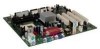
J Processor fan connector X Intel 82801DB (ICH4) K DIMM sockets Y Front panel USB 2.0 header L Serial port B connector (optional) Z Front panel USB 2.0 wake confriguration jumper M Main power connector AA PCI bus add-in card connectors N Diskette drive connector Figure 1. Desktop Board - Intel BOXD845GLLY | Product Guide - Page 10
://support.intel.com/support/motherboards/desktop/ For instructions on installing or upgrading the processor, see Chapter 2 on page 19. Desktop Boards D845GLLY and D845GLAD require an ATX12V or SFX-12V compliant power supply to function according to Intel desktop board specifications. Both desktop - Intel BOXD845GLLY | Product Guide - Page 11
include the PC SDRAM Specification (memory component specific), the PC Unbuffered DIMM Specification. To view or download these specifications, refer to this Intel World Wide Web site: http://www.intel.com/technology/memory/pcsdram/spec/ Desktop Board D845GLLY supports system memory as defined below - Intel BOXD845GLLY | Product Guide - Page 12
Desktop Boards D845GLLY and D845GLAD Product Guide Intel® 82845GL Graphics and Memory Controller Hub (GMCH) The GMCH provides the processor, system memory, and hub interfaces in the Intel 845GL chipset platform. Features on Desktop Boards D845GLLY and D845GLAD include: • Single processor support - Intel BOXD845GLLY | Product Guide - Page 13
integrated graphics on Desktop Boards D845GLLY and D845GLAD feature: • Intel 845GL chipset • Intel Extreme Graphics Audio Subsystem The audio subsystem features the following: • Intel 845GL chipset (AC '97) • Sigmatel† STAC9750 audio codec ✏ NOTE The line out connector, located on the back panel, is - Intel BOXD845GLLY | Product Guide - Page 14
Intel Desktop Boards D845GLLY and D845GLAD Product Guide RJ-45 LAN Connector LEDs Two LEDs are built into the RJ-45 LAN connector. Table 3 describes the LED states when the Intel desktop board is powered up and the LAN subsystem is operating. Table 3. RJ-45 LAN Connector LEDs LED Color Green - Intel BOXD845GLLY | Product Guide - Page 15
Slots Desktop Boards D845GLLY and D845GLAD have four PCI bus add-in card connectors. BIOS The BIOS provides the Power-On Self-Test (POST), the BIOS Setup program, the PCI and IDE auto-configuration utilities, and the video BIOS. The BIOS is stored in the Firmware Hub. The BIOS can be updated by - Intel BOXD845GLLY | Product Guide - Page 16
state. The Intel desktop board's standby power indicator, shown in Figure 2, is lit when there is standby power to the system. This includes the memory modules and PCI bus connectors, even when the computer appears to be off. If the system has a dual-colored power LED on the front panel, the sleep - Intel BOXD845GLLY | Product Guide - Page 17
PME# wake up support Power Connectors Desktop Boards D845GLLY and D845GLAD have two power connectors. See Figure 14 on page 62 for the location of the power connectors. Fan Connectors Desktop Boards D845GLLY and D845GLAD have two chassis fan connectors and one processor fan connector. See Figure 14 - Intel BOXD845GLLY | Product Guide - Page 18
in CMOS RAM and the clock current when the computer is turned off. See Chapter 2 starting on page 19 for instructions on how to replace the battery. Real-Time Clock Desktop Boards D845GLLY and D845GLAD have a time-of-day clock and 100-year calendar. A battery on the Intel desktop board keeps the - Intel BOXD845GLLY | Product Guide - Page 19
desktop board • Install and remove a processor • Install and remove memory • Connect the IDE cable • Connect the front panel header (not included) • Set the BIOS jumper • Install the front panel audio solution (not included) • Install the front panel telecommunications links, networks, or modems - Intel BOXD845GLLY | Product Guide - Page 20
Intel Desktop Boards D845GLLY and D845GLAD Product Guide Installing the I/O Shield The Intel desktop board comes with an I/O shield. When installed in the chassis, the shield blocks radio frequency transmissions, protects internal components from dust and foreign objects, and promotes - Intel BOXD845GLLY | Product Guide - Page 21
Installing and Replacing Desktop Board Components Installing and Removing the Desktop Board Refer to your chassis manual for instructions on installing and removing the Intel desktop board. WARNING This procedure should be done only by qualified technical personnel. Disconnect the computer from its - Intel BOXD845GLLY | Product Guide - Page 22
Boards D845GLLY and D845GLAD have an integrated processor fan heat sink retention mechanism (RM). For instructions on how to install the processor fan heat sink to the integrated processor fan heat sink RM, refer to the boxed processor manual or the Intel World Wide Web site at: http://support.intel - Intel BOXD845GLLY | Product Guide - Page 23
the PC Serial Presence Detect Specification at: http://www.intel.com/technology/memory/pcsdram/spec/ ✏ NOTE Remove the PCI bus connector 1 card before installing or upgrading memory to avoid interference with the memory retention mechanism. Desktop Boards D845GLLY and D845GLAD have two DIMM sockets - Intel BOXD845GLLY | Product Guide - Page 24
Intel Desktop Boards D845GLLY and D845GLAD Product Guide Installing DIMMs To install DIMMs, follow these steps: 8. Replace the computer's cover and reconnect the AC power cord. Removing DIMMs To remove a memory module, follow these steps: 1. Observe the precautions in "Before You Begin" on page 19. - Intel BOXD845GLLY | Product Guide - Page 25
an ATAPI CD-ROM drive. For correct function of the cable: • Attach the cable end with the single connector to the Intel desktop board (see Figure 8, A). • Attach the cable end with the two closely spaced connectors to the drives (see Figure 8, B). A B Figure 8. Connecting the IDE Cable OM13686 25 - Intel BOXD845GLLY | Product Guide - Page 26
Intel Desktop Boards D845GLLY and D845GLAD Product Guide Connecting the Front Panel Header Before connecting the front panel header, observe the precautions in "Before You Begin" on page 19. Refer to Table 32 on page 65 for pin assignments. Setting the Jumper Blocks - Intel BOXD845GLLY | Product Guide - Page 27
from the header (this disables the back panel audio connectors). 5. Install a correctly keyed and shielded front panel audio cable. 6. Connect the audio cable to the front panel audio solution. 7. Replace the cover. To restore back panel operations, follow these steps: 1. Observe the precautions - Intel BOXD845GLLY | Product Guide - Page 28
Intel Desktop Boards D845GLLY and D845GLAD Product Guide Clearing Passwords This procedure assumes that the board is installed in the the Setup program. Setup displays the maintenance menu. 8. Use the arrow keys to select Clear Passwords. Press and Setup displays a pop-up screen requesting - Intel BOXD845GLLY | Product Guide - Page 29
Replacing Desktop Board Components Replacing the Battery A coin-cell battery (CR2032) powers the real-time clock and CMOS memory. When VSB applied. When the voltage drops below a certain level, the BIOS Setup program settings stored in CMOS RAM (for example, the date and time) might not be accurate - Intel BOXD845GLLY | Product Guide - Page 30
Intel Desktop Boards D845GLLY and D845GLAD Product Guide VORSICHT Bei falschem Einsetzen einer neuen Batterie besteht Explosionsgefahr. Die Batterie darf nur durch denselben oder einen entsprechenden, vom Hersteller empfohlenen Batterietyp ersetzt werden. Entsorgen - Intel BOXD845GLLY | Product Guide - Page 31
the "+" and "-" on the battery. 6. With a medium flat-bladed screwdriver, gently pry the battery free from its connector (for Desktop Board D845GLLY only). 7. Install the new battery in the connector, orienting the "+" and "-" correctly. 8. Replace the computer cover. OM13688 Figure 10. Removing the - Intel BOXD845GLLY | Product Guide - Page 32
Intel Desktop Boards D845GLLY and D845GLAD Product Guide 32 - Intel BOXD845GLLY | Product Guide - Page 33
the BIOS with the Intel Express BIOS Update utility: 1. Go to the Intel World Wide Web site: http://support.intel.com/support/motherboards/desktop/ 2. Navigate to the D845GLLY or D845GLAD page and click the Express BIOS Update utility file for the D845GLLY or D845GLAD board's BIOS. 3. Download the - Intel BOXD845GLLY | Product Guide - Page 34
Intel Desktop Boards D845GLLY and D845GLAD Product Guide ✏ NOTE Review the instructions distributed with the update utility before attempting a BIOS update. The Intel Flash Memory Update Utility allows you to: • Update the BIOS in flash memory • Update the language section of the BIOS Updating the - Intel BOXD845GLLY | Product Guide - Page 35
Updating the BIOS 6. Listen to the speaker: • Upon applying power, drive A will begin to show activity. In about a minute, two beeps are heard and drive A activity ceases (temporarily) indicating the successful recovery of the BIOS core. Drive A activity will begin again followed by two more beeps - Intel BOXD845GLLY | Product Guide - Page 36
Intel Desktop Boards D845GLLY and D845GLAD Product Guide 36 - Intel BOXD845GLLY | Product Guide - Page 37
section may not show the latest settings. For the latest BIOS settings, refer to the Intel Desktop Board D845GLLY/D845GLAD Technical Product Specification or the Intel World Wide Web site: http://support.intel.com/support/motherboards/desktop ✏ NOTE For reference purposes, you should write down the - Intel BOXD845GLLY | Product Guide - Page 38
Intel Desktop Boards D845GLLY and D845GLAD Product Guide Table 7 shows the function keys available for menu screens. Table 7. BIOS Setup Program Function Keys BIOS Setup Program Function Key or or Description Selects a different menu screen Moves cursor up - Intel BOXD845GLLY | Product Guide - Page 39
of the BIOS. Displays processor type. Displays processor speed. Displays the system bus speed. Dislays the system memory speed. Displays the size of second-level cache and whether it is ECC-capable. Displays the total amount of RAM. Displays the amount and type of RAM in the memory banks. Selects - Intel BOXD845GLLY | Product Guide - Page 40
Desktop Boards D845GLLY and D845GLAD Product Guide Advanced Menu Maintenance Main Advanced Security Power Boot Exit PCI Configuration Boot Configuration Peripheral Configuration IDE Configuration Diskette Configuration Event Log Configuration Video Configuration USB Configuration Chipset - Intel BOXD845GLLY | Product Guide - Page 41
Security Power Boot Exit PCI Configuration Boot Configuration Peripheral Configuration IDE Configuration Diskette Configuration Event Log Configuration Video Configuration USB Configuration Chipset Configuration The submenu shown in Table 11 is used to configure the IRQ priority of PCI slots - Intel BOXD845GLLY | Product Guide - Page 42
Intel Desktop Boards D845GLLY and D845GLAD Product Guide Boot Configuration Submenu Maintenance Main Advanced Security Power Boot Exit PCI Configuration Boot Configuration Peripheral Configuration IDE Configuration Diskette Configuration Event Log Configuration Video Configuration USB - Intel BOXD845GLLY | Product Guide - Page 43
Diskette Configuration Event Log Configuration Video Configuration USB Configuration Chipset Configuration This submenu shown in port A. Auto assigns the first free COM port, normally COM1, the address 3F8h, and the interrupt IRQ4. An * (asterisk) displayed next to an address indicates a conflict - Intel BOXD845GLLY | Product Guide - Page 44
Intel Desktop Boards D845GLLY and D845GLAD Product Guide Table 13. Peripheral Configuration Submenu (continued) Feature for the parallel port, if Parallel Port is Enabled. Audio LAN Device (This feature is present only when there is onboard LAN) • Disabled • Enabled (default) • Disabled • - Intel BOXD845GLLY | Product Guide - Page 45
Diskette Configuration Event Log Configuration Video Configuration USB Configuration Chipset Configuration This submenu shown in Causes the BIOS to insert a delay before attempting to detect IDE drives in the system. Reports type of connected IDE device. When selected, displays the Primary IDE - Intel BOXD845GLLY | Product Guide - Page 46
Boards D845GLLY and D845GLAD Product Guide Primary/Secondary IDE Master/Slave Submenus Maintenance Main Advanced Security PCI Configuration Boot Configuration Peripheral Configuration IDE Configuration Diskette Configuration Event Log Configuration Video Configuration USB Configuration Chipset - Intel BOXD845GLLY | Product Guide - Page 47
Security Power Boot Exit PCI Configuration Boot Configuration Peripheral Configuration IDE Configuration Diskette Configuration Event Log Configuration Video Configuration USB Configuration Chipset Configuration This submenu shown in Table 16 is used to configure the diskette drive. Table 16 - Intel BOXD845GLLY | Product Guide - Page 48
Intel Desktop Boards D845GLLY and D845GLAD Product Guide Event Log Configuration Submenu Maintenance Main Advanced Security Power Boot Exit PCI Configuration Boot Configuration Peripheral Configuration IDE Configuration Floppy Configuration Event Log Configuration Video Configuration USB - Intel BOXD845GLLY | Product Guide - Page 49
• 512 KB • 1 MB (default) • 8 MB Description Amount of system memory available for direct access by the graphics device. Allows selecting and AGP or PCI video controller as the display device that will be active when the system boots. Controls how much system RAM is reserved for use by the internal - Intel BOXD845GLLY | Product Guide - Page 50
Boards D845GLLY and D845GLAD Product Guide USB Configuration Submenu Maintenance Main Advanced Security Power Boot Exit PCI Configuration Boot Configuration Peripheral Configuration IDE Configuration Diskette Configuration Event Log Configuration Video Configuration USB Configuration Chipset - Intel BOXD845GLLY | Product Guide - Page 51
Diskette Configuration Event Log Configuration Video Configuration USB Configuration Chipset Configuration The menu shown in programmed according to the memory detected. Manual - Aggressive selects the most aggressive user defiend timings. Manual - User Defined allows manual override of detected - Intel BOXD845GLLY | Product Guide - Page 52
Intel Desktop Boards D845GLLY and D845GLAD Product Guide Security Menu Maintenance Main Advanced User access Level (Note 2) • Limited • No access • View Only • Full (default) Sets BIOS Setup Utility access rights for user level. Notes: 1. This feature appears only if a user password has - Intel BOXD845GLLY | Product Guide - Page 53
• Power-On • Stay Off (default) • Power-On Description When selected, displays the ACPI submenu. Determines the mode of operation if a power loss occurs. Stay the ACPI features. Table 23. ACPI Submenu Feature Options Suspend Mode Wake on LAN from S5 • S1 (POS) only (default) • S1 & S3 (STR - Intel BOXD845GLLY | Product Guide - Page 54
Boards D845GLLY and D845GLAD Product Guide Boot Menu Maintenance Main Advanced Security Power Boot Exit The menu shown in Table 24 is used to set the boot features and the boot sequence. Table 24. Boot Menu Feature Silent Boot Intel® Rapid BIOS Boot Scan User Flash Area PXE Boot to LAN - Intel BOXD845GLLY | Product Guide - Page 55
for the first through final boot devices are, respectively listed below. The BIOS supports up to sixteen total boot devices in any combination of the boot device is installed. This list will display up to twelve hard disk drives, the maximum number of hard disk drives supported by the BIOS. 55 - Intel BOXD845GLLY | Product Guide - Page 56
Intel Desktop Boards D845GLLY and D845GLAD Product Guide Removable Devices Submenu Maintenance Main Advanced Security type is installed. This list will display up to four removable devices, the maximum number of removable devices supported by the BIOS. ATAPI CD-ROM Drives Maintenance Main - Intel BOXD845GLLY | Product Guide - Page 57
Defaults Saves the current values as custom defaults. Normally, the BIOS reads the Setup values from flash memory. If this memory is corrupted, the BIOS reads the custom defaults. If no custom defaults are set, the BIOS reads the factory defaults. Discard Changes Discards changes without exiting - Intel BOXD845GLLY | Product Guide - Page 58
Intel Desktop Boards D845GLLY and D845GLAD Product Guide 58 - Intel BOXD845GLLY | Product Guide - Page 59
Board Connectors The board connectors can be divided into three groups: • Back panel connectors • Midboard connectors - Audio connectors - Power and hardware connectors - Add-in board and peripheral interface connectors • Front panel headers CAUTION Many of the midboard and front panel connectors - Intel BOXD845GLLY | Product Guide - Page 60
Intel Desktop Boards D845GLLY and D845GLAD Product Guide Back Panel Connectors Figure 12 shows the back panel connectors. A C F B Item A B C D E F G H I J K D E Description PS/2 mouse port PS/2 keyboard port Parallel port Serial port A VGA port RJ-45 (optional) USB 2.0 port USB 2.0 port Mic - Intel BOXD845GLLY | Product Guide - Page 61
(optional) Auxiliary line in (ATAPI) CD-ROM (ATAPI) Black White Black Figure 13. Audio Connectors OM13690 Table 30 shows the pin assignments for the optional front panel audio header. Table 30. Front Panel Audio Header Signal Names (J8A1) Pin Signal Name 1 AUD-MIC 3 AUD-MIC-BIAS 5 AUD - Intel BOXD845GLLY | Product Guide - Page 62
D845GLLY and D845GLAD require an ATX12V or SFX-12V compliant power supply to function according to desktop board specifications. Both desktop boards have two ATX12V or SFX-12V compliant power supply connectors that are needed to provide extra power to the Intel 845GL chipset and Pentium 4 processor - Intel BOXD845GLLY | Product Guide - Page 63
Add-In Card and Peripheral Interface Connectors Figure 15 shows the add-in card and peripheral interface connectors. A BCD Technical Reference 2 40 1 39 2 40 2 34 1 39 1 33 G F Item A B C D Description PCI bus connector 4 PCI bus connector 3 PCI bus connector 2 (SMBus routed) PCI bus - Intel BOXD845GLLY | Product Guide - Page 64
Intel Desktop Boards D845GLLY and D845GLAD Product Guide Front Panel Headers Figure 16 shows the location of the front panel headers. 1 2 3 4 5 6 7 9 10 A 1 2 3 4 5 6 7 8 10 B 1 2 3 4 5 6 7 8 9 C 1 2 Item A B C D D OM13694 Description Front panel audio (optional) ( - Intel BOXD845GLLY | Product Guide - Page 65
6 USB_FPP1+ 8 Ground 10 USB_FP_OC0 Note: USB ports may be assigned as needed. Table 32 shows the pin assignments for the front panel header. Table 32. Front Panel Header (J9G1) Pin Signal In/Out Description Pin Signal In/Out Description Hard Drive Activity LED Power LED 1 HD_PWR Out - Intel BOXD845GLLY | Product Guide - Page 66
Intel Desktop Boards D845GLLY and D845GLAD Product Guide Desktop Board Resources Memory Map Table 33. System Memory Map Address Range (decimal) 1024 K - 2097152 K 960 K - 1024 K 896 K - 960 K 800 K - 896 K Address Range (hex) 100000 - 7FFFFFF F0000 - FFFFF E0000 - EFFFF C8000 - DFFFF 640 K - - Intel BOXD845GLLY | Product Guide - Page 67
Interrupts Table 35. Interrupts IRQ System Resource NMI I/O channel check 0 Reserved, interval timer 1 Reserved, keyboard buffer full 2 Reserved, cascade interrupt from slave PIC 3 COM2* 4 COM1* 5 LPT2 (Plug & Play option) / ** 6 Diskette drive controller 7 LPT1* 8 Real time - Intel BOXD845GLLY | Product Guide - Page 68
Intel Desktop Boards D845GLLY and D845GLAD Product Guide 68 - Intel BOXD845GLLY | Product Guide - Page 69
Boards D845GLLY and D845GLAD report POST errors in two ways: • By sounding a beep code • By displaying an error message on the monitor BIOS Beep Codes The BIOS beep codes are listed in Table 36. The BIOS also issues a beep code (one long tone followed by two short tones) during POST if the video - Intel BOXD845GLLY | Product Guide - Page 70
Intel Desktop Boards D845GLLY and D845GLAD Product Guide BIOS Error Messages When a recoverable error occurs during the POST, the BIOS displays an error message describing the problem. Table 37. BIOS Error Messages Error Message Explanation GA20 Error An error occurred with Gate-A20 when - Intel BOXD845GLLY | Product Guide - Page 71
may be a problem with the system. Memory Size Changed Memory size has changed since the last boot. If no memory was added or removed, then memory may be bad. No Boot Device Available System did not find a device to boot. Off Board Parity Error A parity error occurred on an offboard card. This - Intel BOXD845GLLY | Product Guide - Page 72
Intel Desktop Boards D845GLLY and D845GLAD Product Guide 72 - Intel BOXD845GLLY | Product Guide - Page 73
) regulations, and product certification markings for Desktop Boards D845GLLY and D845GLAD. • Instructions and precautions for integrators who are installing the Intel desktop board in a chassis. Safety Regulations Desktop Boards D845GLLY and D845GLAD comply with the safety regulations stated in - Intel BOXD845GLLY | Product Guide - Page 74
Intel Desktop Boards D845GLLY and D845GLAD Product Guide Product Certification Markings Desktop Boards D845GLLY and D845GLAD have the following product certification markings: • UL joint US/Canada Recognized Component mark: consists of small c followed by a stylized backward UR and followed by a - Intel BOXD845GLLY | Product Guide - Page 75
and test the desktop board, observe all warnings and cautions in the installation instructions. To avoid injury, be careful of: • Sharp pins on connectors • Sharp pins on printed circuit assemblies • Rough edges and sharp corners on the chassis • Hot components (like processors, voltage regulators - Intel BOXD845GLLY | Product Guide - Page 76
Intel Desktop Boards D845GLLY and D845GLAD Product Guide Chassis and The Industry Canada statement at the front of this product guide demonstrates compliance with Canadian EMC the manufacturer's instructions. Use Only for Intended Applications All Intel desktop processor boards are evaluated
-
 1
1 -
 2
2 -
 3
3 -
 4
4 -
 5
5 -
 6
6 -
 7
7 -
8
-
9
-
10
-
11
-
12
-
13
-
14
-
15
-
16
-
17
-
18
-
19
-
20
-
21
-
22
-
23
-
24
-
25
-
26
-
27
-
28
-
29
-
30
-
31
-
32
-
33
-
34
-
35
-
36
-
37
-
38
-
39
-
40
-
41
-
42
-
43
-
44
-
45
-
46
-
47
-
48
-
49
-
50
-
51
-
52
-
53
-
54
-
55
-
56
-
57
-
58
-
59
-
60
-
61
-
62
-
63
-
64
-
65
-
66
-
67
-
68
-
69
-
70
-
71
-
72
-
73
-
74
-
75
-
76
 |
 |
Intel
®
Desktop Boards
D845GLLY and D845GLAD
Product Guide
Order Number:
A84618-001