Intel BOXD955XBKLKR Product Specification
Intel BOXD955XBKLKR - Motherboard 955X Express Chip ATX Manual
 |
UPC - 735858173803
View all Intel BOXD955XBKLKR manuals
Add to My Manuals
Save this manual to your list of manuals |
Intel BOXD955XBKLKR manual content summary:
- Intel BOXD955XBKLKR | Product Specification - Page 1
® Desktop Board D955XBK Technical Product Specification April 2005 Order Number: D14065-001 The Intel® Desktop Board D955XBK may contain design defects or errors known as errata that may cause the product to deviate from published specifications. Current characterized errata are documented in the - Intel BOXD955XBKLKR | Product Specification - Page 2
not be supported without further evaluation by Intel. Intel Corporation may Intel may make changes to specifications and product descriptions at any time, without notice. Designers must not rely on the absence or characteristics of any features or instructions marked "reserved" or "undefined." Intel - Intel BOXD955XBKLKR | Product Specification - Page 3
intended to provide detailed, technical information about the Intel Desktop Board D955XBK and its components to the vendors, system integrators, and other engineers and technicians who need this level of information. It is specifically not intended for general audiences. What This Document Contains - Intel BOXD955XBKLKR | Product Specification - Page 4
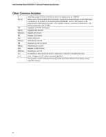
Intel Desktop Board D955XBK Technical Product Specification Other Common Notation # (NxnX) GB GB/sec Gbits/sec KB Kbit kbits/sec MB MB/sec Mbit Mbits/sec xxh x.x V * Used after a signal name to - Intel BOXD955XBKLKR | Product Specification - Page 5
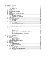
Options 11 1.1.3 Board Layout 12 1.1.4 Block Diagram 14 1.2 Online Support ...15 1.3 Processor ...15 1.4 System Memory ...16 1.4.1 Memory Configurations 17 1.5 Intel® 955X Chipset...21 1.5.1 USB ...21 1.5.2 IDE Support 21 1.5.3 Real-Time Clock, CMOS SRAM, and Battery 23 1.6 Discrete - Intel BOXD955XBKLKR | Product Specification - Page 6
Intel Desktop Board D955XBK Technical Product Specification 2 Technical Reference 2.1 Memory Resources ...45 2.1.1 Addressable Memory 45 2.1.2 Memory PCI IDE Support 82 3.3 System Management BIOS (SMBIOS 83 3.4 Legacy USB Support...83 3.5 BIOS Updates ...84 3.5.1 Language Support 84 3.5.2 Custom - Intel BOXD955XBKLKR | Product Specification - Page 7
® Rapid BIOS Boot 86 3.7.1 Peripheral Selection and Configuration 86 3.7.2 Intel Rapid BIOS Boot 86 3.8 BIOS Security Features 87 4 Error Messages and Beep Codes 4.1 Feature Summary ...10 2. Manufacturing Options 11 3. Components Shown in Figure 1 13 4. Supported Memory Configurations 16 vii - Intel BOXD955XBKLKR | Product Specification - Page 8
Intel Desktop Board D955XBK Technical Product Specification 5. LAN Connector LED States 31 6. Effects of Pressing the Connector Current Capability 72 37. Thermal Considerations for Components 75 38. Environmental Specifications 76 39. Safety Regulations ...77 40. EMC Regulations ...77 41. Product - Intel BOXD955XBKLKR | Product Specification - Page 9
1 Product Description What This Chapter Contains 1.1 Overview ...10 1.2 Online Support ...15 1.3 Processor ...15 1.4 System Memory ...16 1.5 Intel® 955X Chipset...21 1.6 Discrete Serial ATA Interface (Optional 24 1.7 PCI Express Connectors 24 1.8 Auxiliary Power (AUX PWR) Output Connector ( - Intel BOXD955XBKLKR | Product Specification - Page 10
Dual Inline Memory Module (DIMM) sockets • Support for 667 and 533 MHz DDR2 DIMMs • Support for up to 8 GB of system memory • Support for ECC and non-ECC memory Intel® 955X Chipset, consisting of: • Intel® 82955X Memory Controller Hub (MCH) • Intel® 82801GR I/O Controller Hub (ICH7-R) • Firmware - Intel BOXD955XBKLKR | Product Specification - Page 11
ATAPI CD-ROM connector A 1 x 4-pin ATAPI-style connector for connecting an internal ATAPI CD-ROM drive to the audio mixer Audio Subsystem Intel High Definition Audio subsystem in one of the following configurations: • 8-channel (7.1) audio subsystem with five analog audio outputs and two S/PDIF - Intel BOXD955XBKLKR | Product Specification - Page 12
Intel Desktop Board D955XBK Technical Product Specification 1.1.3 Board Layout Figure 1 shows the location of the major components. A B C DE F G H I J K OO NN L MM LL KK M JJ N O II P Q HH GG EE CC AA Y W U T FF DD - Intel BOXD955XBKLKR | Product Specification - Page 13
(optional) K Rear chassis fan connector L LGA775 processor socket M Intel 82955X MCH N Processor fan connector O Intel 82801GR I/O Controller Hub (ICH7-R) P DIMM Channel A sockets [2] Q DIMM Channel B sockets [2] R I/O controller S Power connector T Diskette drive connector - Intel BOXD955XBKLKR | Product Specification - Page 14
Drive Connector PCI Express x16 Interface PCI Express x16 Connector Intel 82955X Memory Controller Hub (MCH) DMI Interconnect Intel 82801GR I/O Controller Hub (ICH7-R) Firmware Hub (FWH) -- or -SPI Flash Device Intel 955X Chipset LPC Bus SMBus Channel A DIMMs (2) Dual-Channel Memory Bus - Intel BOXD955XBKLKR | Product Specification - Page 15
Web site: http://www.intel.com/design/motherbd http://support.intel.com/support/motherboards/desktop http://developer.intel.com/design/motherbd/bk/bk_available.htm http://www.intel.com/design/litcentr http://developer.intel.com/design/chipsets/datashts http://intel.com/design/motherbd/gen_indx.htm - Intel BOXD955XBKLKR | Product Specification - Page 16
Intel Desktop Board D955XBK Technical Product Specification 1.4 System Memory The board has four DIMM sockets and supports the following memory features: • 1.8 V and 1.9 V DDR2 SDRAM DIMMs • Unbuffered, single-sided or double-sided DIMMs with the following restriction: Double-sided DIMMS with x16 - Intel BOXD955XBKLKR | Product Specification - Page 17
Product Description 1.4.1 Memory Configurations The Intel 82955X MCH supports two types of memory organization: • Dual 3 illustrates the memory channel and DIMM configuration. NOTE The DIMM0 sockets of both channels are blue. The DIMM1 sockets of both channels are black. Channel A, DIMM 0 Channel A, - Intel BOXD955XBKLKR | Product Specification - Page 18
Intel Desktop Board D955XBK Technical Product Specification 1.4.1.1 Dual Channel (Interleaved) Mode Configurations Figure 4 shows a dual channel configuration using two DIMMs. In this example, the DIMM0 (blue) sockets of both channels are populated with identical DIMMs. 1 GB 1 GB Channel A, DIMM - Intel BOXD955XBKLKR | Product Specification - Page 19
Product Description Figure 6 shows a dual channel configuration using four DIMMs. In this example, the combined capacity of the two DIMMs in Channel A equal the combined capacity of the two DIMMs in Channel B. Also, the DIMMs are matched between DIMM0 and DIMM1 of both channels. 256 MB 512 MB 256 - Intel BOXD955XBKLKR | Product Specification - Page 20
Technical Product Specification 1.4.1.2 Single Channel (Asymmetric) Mode Configurations NOTE Dual channel (Interleaved) mode configurations provide the highest memory throughput. Figure 7 shows a single channel configuration using one DIMM. In this example, only the DIMM0 (blue) socket of Channel - Intel BOXD955XBKLKR | Product Specification - Page 21
a centralized controller for the board's I/O paths. For information about The Intel 955X chipset Resources used by the chipset Refer to http://developer.intel.com/ Chapter 2 1.5.1 USB The board supports up to eight USB 2.0 ports, supports UHCI and EHCI, and uses UHCI- and EHCI-compatible drivers - Intel BOXD955XBKLKR | Product Specification - Page 22
Intel Desktop Board D955XBK Technical Product Specification • Ultra DMA: DMA protocol on IDE bus supporting host and target throttling and transfer rates of up to 33 MB/sec. • ATA-66: DMA protocol on IDE bus supporting host and target throttling and transfer rates of up to 66 MB/sec. ATA-66 - Intel BOXD955XBKLKR | Product Specification - Page 23
Product Description 1.5.2.3 Serial ATA RAID The ICH7-R supports the following RAID (Redundant Array of Independent Drives the real-time clock and CMOS memory. When the computer is not plugged into a wall socket, the battery has an estimated life of three years. When the computer is plugged in, - Intel BOXD955XBKLKR | Product Specification - Page 24
Intel Desktop Board D955XBK Technical Product Specification 1.6 Discrete Serial ATA Interface (Optional) As a manufacturing option, the board provides a Silicon Image Sil 3114 Serial ATA (SATA) controller and four connectors (that support one device per connector) for SATA devices. These - Intel BOXD955XBKLKR | Product Specification - Page 25
) The optional IEEE-1394 interface addresses interconnection of both computer peripherals and consumer electronics with these features: • IEEE-1394a and IEEE-1394b operation • Support for up to 63 peer-to-peer devices • Operation ranging from 100 Mbits/sec to 800 Mbits/sec (depending on cable type - Intel BOXD955XBKLKR | Product Specification - Page 26
Intel Desktop Board D955XBK Technical Product Specification For information about The location of the back connector Refer to Figure 18, page 55 1.10.3 Diskette Drive Controller The I/O controller supports one diskette drive. Use the BIOS Setup program to configure the diskette drive interface. - Intel BOXD955XBKLKR | Product Specification - Page 27
connected or disconnected. For information about The location of the keyboard and mouse connectors Refer to Figure 18, page 55 1.11 Audio Subsystem The board supports the Intel High Definition audio subsystem based on the Sigmatel 9221 or the Sigmatel 9220 audio codec. The audio subsystem - Intel BOXD955XBKLKR | Product Specification - Page 28
Desktop Board D955XBK Technical Product Specification 1.11.3 8-Channel (7.1) Audio Subsystem The 8-channel (7.1) audio subsystem includes the following: • Intel 82801GR I/O Controller Hub (ICH7-R) • Sigmatel 9221 audio codec • Microphone input that supports a single dynamic, condenser, or electret - Intel BOXD955XBKLKR | Product Specification - Page 29
Product Description Figure 10 is a block diagram of the 8-channel (7.1) audio subsystem. 82801GR I/O Controller Hub (ICH7-R) Intel High Definition Audio Link Sigmatel 9221 Audio Codec Front Panel Mic In Front Panel Line Out Mic In/Retasking Jack Side Surround L-R/Line In/Retasking - Intel BOXD955XBKLKR | Product Specification - Page 30
Desktop Board D955XBK Technical Product Specification 1.11.4 6-Channel (5.1) Audio Subsystem The 6-channel (5.1) audio subsystem includes the following: • Intel 82801GR I/O Controller Hub (ICH7-R) • Sigmatel 9220 audio codec • Microphone input that supports a single dynamic, condenser, or electret - Intel BOXD955XBKLKR | Product Specification - Page 31
) Ethernet Controller and an RJ-45 LAN connector with integrated status LEDs. 1.12.1 Intel® 82573E/82573V/82574V Gigabit Ethernet Controller The Intel 82573E/82573V/82574V Gigabit Ethernet Controller supports the following features: • PCI Express link • 10/100/1000 IEEE 802.3 compliant • Compliant - Intel BOXD955XBKLKR | Product Specification - Page 32
Intel Desktop Board D955XBK Technical Product Specification 1.12.3 Alert Standard Format (ASF) Support The board provides the following ASF support for PCI Express x1 bus add-in LAN cards and PCI Conventional bus add-in LAN cards installed in PCI Conventional bus slot 2: • Monitoring of - Intel BOXD955XBKLKR | Product Specification - Page 33
diagnose problems quickly to reduce end-user downtime • Protecting the enterprise against malicious software attacks: ⎯ Intel AMT helps ⎯ TCP/IP ⎯ HTTP web GUI ⎯ XML/SOAP API • Remote troubleshooting and recovery that can significantly reduce desk-side visits and potentially increasing efficiency - Intel BOXD955XBKLKR | Product Specification - Page 34
Desktop Board D955XBK Technical Product Specification 1.12.5 LAN Subsystem Software LAN software and drivers are available from Intel's World Wide Web site. For information about Obtaining LAN software and drivers Refer to Section 1.2, page 15 1.13 Hardware Management Subsystem The hardware - Intel BOXD955XBKLKR | Product Specification - Page 35
1.13.2 Thermal Monitoring Figure 14 shows the location of the sensors and fan connectors. 4 G 1 3 1 Product Description A B C 4 1 D 31 F E OM17725 Item A B C D E F G Description Remote ambient temperature sensor Thermal diode, located on processor die Ambient temperature sensor, - Intel BOXD955XBKLKR | Product Specification - Page 36
Board D955XBK Technical Product Specification 1.13.3 Fan Monitoring Fan monitoring can be implemented using Intel Desktop Utilities or third- Section 1.14.2.2, page 40 1.13.4 Chassis Intrusion and Detection The board supports a chassis security feature that detects if the chassis cover is removed. - Intel BOXD955XBKLKR | Product Specification - Page 37
Product Description Table 6 lists the system states based on how long the power switch is pressed, depending on how ACPI is configured with an ACPI-aware operating system. Table 6. Effects of Pressing the Power Switch If the system is in this state... Off (ACPI G2/G5 - Soft off) On (ACPI G0 - - Intel BOXD955XBKLKR | Product Specification - Page 38
Intel Desktop Board D955XBK Technical Product Specification Table 7 lists the power states supported by the board along with the associated system power targets. See the ACPI specification battery or external source. No power to the system. Service can be performed safely. Notes: 1. Total system - Intel BOXD955XBKLKR | Product Specification - Page 39
Devices and Events Table 8 lists the devices or specific events that can wake the computer from specific states. Table 8. Wake-up Devices and Events amount of standby current required depends on the wake devices supported and manufacturing options. The board provides several power management - Intel BOXD955XBKLKR | Product Specification - Page 40
Intel Desktop Board D955XBK Technical Product Specification NOTE The use of Resume on Ring and Wake from USB technologies from an ACPI state requires an operating system that provides full ACPI support. 1.14.2.1 Power Connector When an ACPI-enabled system receives the appropriate command, the - Intel BOXD955XBKLKR | Product Specification - Page 41
39 lists the devices and events that can wake the computer from the S3 state. The board supports the PCI Bus Power Management Interface Specification. Add-in boards that also support this specification can participate in power management and can be used to wake the computer. The use of Instantly - Intel BOXD955XBKLKR | Product Specification - Page 42
Intel Desktop Board D955XBK Technical Product Specification 1.14.2.10 +5 V Standby Power Indicator LED The +5 V standby power indicator LED shows that power is still present even when the computer appears to be off. - Intel BOXD955XBKLKR | Product Specification - Page 43
(TPM) is a component on the desktop board that is specifically designed to enhance platform security above-and-beyond the capabilities of are being used unencrypted in plain-text form. The TPM is specifically designed to shield unencrypted keys and platform authentication information from software - Intel BOXD955XBKLKR | Product Specification - Page 44
Intel Desktop Board D955XBK Technical Product Specification 44 - Intel BOXD955XBKLKR | Product Specification - Page 45
2 Technical Reference What This Chapter Contains 2.1 Memory Resources ...45 2.2 DMA Channels ...47 2.3 Fixed I/O Map...48 2.4 PCI Configuration Space Map 49 2.5 Interrupts ...50 2.6 PCI Conventional Interrupt Routing Map 51 2.7 Connectors...53 2.8 Jumper Block ...67 2.9 Mechanical Considerations - Intel BOXD955XBKLKR | Product Specification - Page 46
Intel Desktop Board D955XBK Technical Product Specification 8 GB Top of System Address Space FLASH APIC Reserved Upper 4 GB of address space ~20 MB PCI Memory Range contains PCI, chipsets, Direct Media Interface ( - Intel BOXD955XBKLKR | Product Specification - Page 47
Technical Reference 2.1.2 Memory Map Table 9 lists the system memory map. Table 9. System Memory Map Address Range (decimal) 1024 K - 8388608 K 960 K - 1024 K 896 K - 960 K 800 K - 896 K Address Range (hex) 100000 - 1FFFFFFFF F0000 - FFFFF E0000 - EFFFF C8000 - DFFFF 640 K - 800 K 639 K - 640 K - Intel BOXD955XBKLKR | Product Specification - Page 48
Intel Desktop Board D955XBK Technical Product Specification 2.3 Fixed I/O Map Table 11. I/O Map Address (hex) 0000 - 00FF Size 256 bytes 0170 - 0177 01F0 - 01F7 0228 - 022F (Note 1) 0278 - 027F (Note 1) 02E8 - 02EF (Note 1) - Intel BOXD955XBKLKR | Product Specification - Page 49
01 02 03 00 01 02 03 07 00 00 01 02 03 00 00 00 00 00 Description Memory controller of Intel 82955X component PCI Express x16 graphics port Intel High Definition Audio Controller PCI Express port 1 (PCI Express x1 bus connector 1) PCI Express port 2 (Gigabit Ethernet controller bridge) PCI Express - Intel BOXD955XBKLKR | Product Specification - Page 50
Intel Desktop Board D955XBK Technical Product Specification 2.5 Interrupts The interrupts can be routed through either the Programmable Interrupt Controller (PIC) or the Advanced Programmable Interrupt Controller (APIC) portion of the ICH7-R component. The PIC is supported in Windows 98 SE and - Intel BOXD955XBKLKR | Product Specification - Page 51
sharing and how the interrupt signals are connected between the PCI Conventional bus connectors and onboard PCI Conventional devices. The PCI Conventional specification describes how interrupts can be shared between devices attached to the PCI Conventional bus. In most cases, the small amount of - Intel BOXD955XBKLKR | Product Specification - Page 52
Intel Desktop Board D955XBK Technical Product Specification Table 14. PCI Interrupt Routing Map PCI Interrupt Source IEEE-1394a/b controller PCI bus connector 1 PCI bus connector 2 PCI bus connector 3 PIRQA PIRQB INTA INTD - Intel BOXD955XBKLKR | Product Specification - Page 53
Technical Reference 2.7 Connectors CAUTION Only the following connectors have overcurrent protection: back panel USB, front panel USB, and PS/2. The other internal connectors are not overcurrent protected and should connect only to devices inside the computer's chassis, such as fans and internal - Intel BOXD955XBKLKR | Product Specification - Page 54
Intel Desktop Board D955XBK Technical Product Specification 2.7.1.1 Back Panel Connectors For 8-Channel (7.1) Audio Subsystem Figure 17 shows the location of the back panel connectors for boards equipped with the 8-channel (7.1) audio subsystem. - Intel BOXD955XBKLKR | Product Specification - Page 55
Technical Reference 2.7.1.2 Back Panel Connectors For 6-Channel (5.1) Audio Subsystem Figure 18 shows the location of the back panel connectors for boards equipped with the 6-channel (5.1) audio subsystem. The back panel connectors are color-coded. The figure legend (Table 16) lists the colors used - Intel BOXD955XBKLKR | Product Specification - Page 56
Intel Desktop Board D955XBK Technical Product Specification 2.7.2 Component-side Connectors Figure 19 shows the locations of the component-side connectors. A B C DE F GH I JK L 12 10 12 4 1 1 4 10 1 1 1 1 12 9 10 HH GG FF - Intel BOXD955XBKLKR | Product Specification - Page 57
Technical Reference Table 17. Component-side Connectors Shown in Figure 19 Item/callout from Figure 19 Description A PCI Express x1 bus add-in card connector B Auxiliary rear fan connector C PCI Conventional bus add-in card connector 3 D ATAPI CD-ROM connector (optional) E PCI - Intel BOXD955XBKLKR | Product Specification - Page 58
Intel Desktop Board D955XBK Technical Product Specification Table 18. ATAPI CD-ROM Connector (Optional) Pin Signal Name 1 Left audio input from CD-ROM 2 CD audio differential ground 3 CD audio differential ground 4 Right - Intel BOXD955XBKLKR | Product Specification - Page 59
Table 22. Chassis Intrusion Connector Pin Signal Name 1 Intruder 2 Ground Table 23. SCSI Hard Drive Activity LED Connector (Optional) Pin Signal Name 1 ACT# 2 No connect Table 24. Serial ATA Connectors Pin Signal Name 1 Ground 2 TXP 3 TXN 4 Ground 5 RXN 6 RXP 7 Ground - Intel BOXD955XBKLKR | Product Specification - Page 60
Intel Desktop Board D955XBK Technical Product Specification 2.7.2.1 Power Supply Connectors The board has three power supply connectors: • Main power - a 2 x 12 connector. The board requires a power supply with a 2 x 12 main power cable. • Processor - Intel BOXD955XBKLKR | Product Specification - Page 61
Technical Reference Table 26. Main Power Connector Pin Signal Name Pin 1 +3.3 V 13 2 +3.3 V 14 3 Ground 15 4 +5 V 16 5 Ground 17 6 +5 V 18 7 Ground 19 8 PWRGD (Power Good) 20 9 +5 V (Standby) 21 10 +12 V 22 11 +12 V 23 12 2 x 12 connector detect 24 Table 27. - Intel BOXD955XBKLKR | Product Specification - Page 62
Intel Desktop Board D955XBK Technical Product Specification 2.7.2.2 Add-in Card Connectors The board has the following add-in card connectors: • PCI Express x16; one connector supporting simultaneous transfers up to 8 GBytes/sec • Secondary PCI Express x16/x4 bus; one connector supporting - Intel BOXD955XBKLKR | Product Specification - Page 63
Technical Reference 2.7.2.4 Front Panel Connector This section describes the functions of the front panel connector. Table 31 lists the signal names of the front panel connector. Figure 20 is a connection diagram for the front panel connector. Table 31. Front Panel Connector Pin Signal In/Out - Intel BOXD955XBKLKR | Product Specification - Page 64
Intel Desktop Board D955XBK Technical Product Specification 2.7.2.4.1 Hard Drive Activity LED Connector [Yellow] Pins 1 and 32 and Table 33 are suggested colors only. Actual LED colors are product- or customer-specific. 2.7.2.4.4 Power Switch Connector [Red] Pins 6 and 8 [Red] can be connected to - Intel BOXD955XBKLKR | Product Specification - Page 65
one USB port. • Pins 2, 4, 6, and 8 comprise one USB port. • Use only a front panel USB connector that conforms to the USB 2.0 specification for high- performance USB devices. Power (+5 V DC) One D− USB Port D+ Ground Key (no pin) 1 2 3 4 5 6 7 8 10 Power (+5 V DC) D− One USB - Intel BOXD955XBKLKR | Product Specification - Page 66
Intel Desktop Board D955XBK Technical Product Specification 2.7.2.6 Front Panel IEEE 1394a/b Connectors (Optional) Figure 22 is a connection diagram for the IEEE 1394a/b connectors. TPA+ 1 2 TPA− Ground TPB+ 3 4 Ground 5 6 TPB− +12 V DC 7 8 +12 V - Intel BOXD955XBKLKR | Product Specification - Page 67
Technical Reference 2.8 Jumper Block CAUTION Do not move the jumper with the power on. Always turn off the power and unplug the power cord from the computer before changing a jumper setting. Otherwise, the board could be damaged. Figure 23 shows the location of the jumper block. The 3-pin jumper - Intel BOXD955XBKLKR | Product Specification - Page 68
Intel Desktop Board D955XBK Technical Product Specification 2.9 Mechanical Considerations 80 millimeters by 243.84 millimeters]. Location of the I/O connectors and mounting holes are in compliance with the ATX specification. 6.500 [165.10] 6.100 [154.94] 1.800 [45.72] 5.200 [132.08] 0.00 - Intel BOXD955XBKLKR | Product Specification - Page 69
. NOTE The I/O shield drawings in this document are for reference only. I/O shields compliant with the ATX chassis specification 2.03 are available from Intel. 1.55 REF [0.061] 22.45 [0.884] 7.01 [0.276] Ø 1.00 [0.039] A 0.00 [0.00] 11.81 [0.465] 12.04 [0.474] 12.81 [0.504] 162.3 REF [6.390 - Intel BOXD955XBKLKR | Product Specification - Page 70
Intel Desktop Board D955XBK Technical Product Specification 1.55 REF [0.061] 22.45 [0.884] 7.012 [0.276] Ø 1.00 [0.039] A 0.00 [0.00] 11.811 [0.465] 12.04 [0.474] 162.3 REF [6.390] 20 ± 0.254 TYP [0.787 ± 0. - Intel BOXD955XBKLKR | Product Specification - Page 71
on the board that is similar to a heavy gaming environment with a 500 mA current draw per USB port. These calculations are not based on specific processor values or memory configurations but are based on the minimum and maximum current draw possible from the board's power delivery subsystems to the - Intel BOXD955XBKLKR | Product Specification - Page 72
Intel Desktop Board D955XBK Technical Product Specification 2.10.3 Fan Connector Current Capability CAUTION power supply. The total amount of standby current required depends on the wake devices supported and manufacturing options. System integrators should refer to the power usage values listed in - Intel BOXD955XBKLKR | Product Specification - Page 73
Setup program options to increase processor voltage and frequency above the supported ranges, the temperature in the processor voltage regulator area will rise solely with the reader. Intel makes no warranties or representations that merely following the instructions presented in this document will - Intel BOXD955XBKLKR | Product Specification - Page 74
Desktop Board D955XBK Technical Product Specification A B D C Item A B C D Description Processor voltage regulator area Processor Intel 82955X MCH Intel 82801GR ICH7-R Figure 28. Localized High Temperature Zones OM17724 CAUTION Ensure that the ambient temperature does not exceed the board - Intel BOXD955XBKLKR | Product Specification - Page 75
point of 110 oC is recommended as a starting point for the processor voltage regulator area. For information about Intel Pentium 4 processor datasheets and specification updates Refer to Section 1.2, page 15 2.12 Reliability The Mean Time Between Failures (MTBF) prediction is calculated using - Intel BOXD955XBKLKR | Product Specification - Page 76
Intel Desktop Board D955XBK Technical Product Specification 2.13 Environmental Table 38 lists the environmental specifications for the board. Table 38. Environmental Specifications Parameter Temperature Non-Operating Operating Shock Unpackaged Packaged Vibration Unpackaged Packaged Specification - Intel BOXD955XBKLKR | Product Specification - Page 77
Technical Reference 2.14 Regulatory Compliance This section describes the board's compliance with U.S. and international safety and electromagnetic compatibility (EMC) regulations. 2.14.1 Safety Regulations Table 39 lists the safety regulations the Desktop Board D955XBK complies with when - Intel BOXD955XBKLKR | Product Specification - Page 78
Intel Desktop Board D955XBK Technical Product Specification 2.14.2.1 FCC Compliance Statement (USA) Product Type: D955XBK radio frequency energy and, if not installed and used in accordance with the instructions, may cause harmful interference to radio communications. However, there is no guarantee - Intel BOXD955XBKLKR | Product Specification - Page 79
/EEC & 73/23/EEC. Svenska Denna produkt har tillverkats i enlighet med EG-direktiv 89/336/EEC & 73/23/EEC. 2.14.4 Recycling Considerations Intel encourages its customers to recycle its products and their components (e.g., batteries, circuit boards, plastic enclosures, etc.) whenever possible. In the - Intel BOXD955XBKLKR | Product Specification - Page 80
Technical Product Specification 2.14.5 Product Certification Markings (Board Level) Table 41 lists the board's product certification markings. Table 41. Product Certification Markings Description UL joint US/Canada Recognized Component mark. Includes adjacent UL file number for Intel Desktop - Intel BOXD955XBKLKR | Product Specification - Page 81
3.1 Introduction ...81 3.2 Resource Configuration 82 3.3 System Management BIOS (SMBIOS 83 3.4 Legacy USB Support...83 3.5 BIOS Updates ...84 3.6 Boot Options ...85 3.7 Fast Booting Systems with Intel® Rapid BIOS Boot 86 3.8 BIOS Security Features 87 3.1 Introduction The BIOS is stored in - Intel BOXD955XBKLKR | Product Specification - Page 82
Intel Desktop Board D955XBK Technical Product Specification Table automatically sets up the PCI IDE connector with independent I/O channel support. The IDE interface supports hard drives up to ATA-66/100 and recognizes any options by specifying manual configuration in the BIOS Setup program. 82 - Intel BOXD955XBKLKR | Product Specification - Page 83
such as Windows NT*, require an additional interface for obtaining the SMBIOS information. The BIOS supports an SMBIOS table interface for such operating systems. Using this support, an SMBIOS service-level application running on a non-Plug and Play operating system can obtain the SMBIOS information - Intel BOXD955XBKLKR | Product Specification - Page 84
Intel® Flash Memory Update Utility, which requires creation of a boot diskette and manual Review the instructions distributed with the upgrade utility before attempting a BIOS update. For information about The Intel World Wide Web site Refer to Section 1.2, page 15 3.5.1 Language Support - Intel BOXD955XBKLKR | Product Specification - Page 85
second, and the ATAPI CD-ROM third. The fourth device is disabled. 3.6.1 CD-ROM Boot Booting from CD-ROM is supported in compliance to the El Torito bootable CD-ROM format specification. Under the Boot menu in the BIOS Setup program, ATAPI CD-ROM is listed as a boot device. Boot devices are - Intel BOXD955XBKLKR | Product Specification - Page 86
Board D955XBK Technical Product Specification 3.7 Fast Booting Systems with Intel® Rapid BIOS Boot These factors affect the amount of time for a system to complete boot process: • Selecting and configuring peripherals properly • Using an optimized BIOS, such as the Intel® Rapid BIOS 3.7.1 Peripheral - Intel BOXD955XBKLKR | Product Specification - Page 87
Overview of BIOS Features 3.8 BIOS Security Features The BIOS includes security features that restrict access to the BIOS Setup program and who can boot the computer. A supervisor password and a user password can be set for the BIOS Setup program and for booting the computer, with the following - Intel BOXD955XBKLKR | Product Specification - Page 88
Intel Desktop Board D955XBK Technical Product Specification 88 - Intel BOXD955XBKLKR | Product Specification - Page 89
Refer to Figure 1, page 12 4.2 BIOS Beep Codes Whenever a recoverable error occurs during POST, the BIOS displays an error message describing the problem (see Table 46). Table 46. Beep Codes Type Memory error Thermal warning Pattern Three long beeps Four alternating beeps: High tone, low tone - Intel BOXD955XBKLKR | Product Specification - Page 90
Intel Desktop Board D955XBK Technical Product Specification 4.4 Port 80h POST Codes During the POST, the BIOS generates diagnostic progress codes (POST-codes) to I/O port 80h. If the POST fails, execution stops and - Intel BOXD955XBKLKR | Product Specification - Page 91
Error Messages and Beep Codes Table 49. Port 80h POST Codes POST Code 10 11 12 13 21 22 23 24 25 26 27 28 50 51 52 53 - 57 58 59 5A 5B 5C 5D 70 71 72 78 79 7A Description of POST Operation Host Processor Power-on initialization of the host processor (Boot Strap Processor) Host processor Cache - Intel BOXD955XBKLKR | Product Specification - Page 92
Intel Desktop Board D955XBK Technical Product Specification Table 49. Port 80h POST Codes (continued) POST Code 90 the keyboard Detecting the presence of the keyboard Enabling the keyboard Clearing keyboard input buffer Instructing keyboard controller to run Self Test (PS2 only) Mouse (PS2 or USB) - Intel BOXD955XBKLKR | Product Specification - Page 93
OS Boot F4 Entering Sleep state F5 Exiting Sleep state F8 EFI boot service ExitBootServices ( ) has been called F9 EFI runtime service SetVirtualAddressMap ( ) has been called FA EFI runtime service ResetSystem ( ) has been called PEIMs/Recovery 30 Crisis Recovery has initiated per User - Intel BOXD955XBKLKR | Product Specification - Page 94
Intel Desktop Board D955XBK Technical Product Specification Table 50. Typical Port 80h POST Sequence POST Code 21 22 23 25 28 34 E4 12 13 50 51 92 90 94 95 EB
-
 1
1 -
 2
2 -
 3
3 -
 4
4 -
 5
5 -
 6
6 -
 7
7 -
8
-
9
-
10
-
11
-
12
-
13
-
14
-
15
-
16
-
17
-
18
-
19
-
20
-
21
-
22
-
23
-
24
-
25
-
26
-
27
-
28
-
29
-
30
-
31
-
32
-
33
-
34
-
35
-
36
-
37
-
38
-
39
-
40
-
41
-
42
-
43
-
44
-
45
-
46
-
47
-
48
-
49
-
50
-
51
-
52
-
53
-
54
-
55
-
56
-
57
-
58
-
59
-
60
-
61
-
62
-
63
-
64
-
65
-
66
-
67
-
68
-
69
-
70
-
71
-
72
-
73
-
74
-
75
-
76
-
77
-
78
-
79
-
80
-
81
-
82
-
83
-
84
-
85
-
86
-
87
-
88
-
89
-
90
-
91
-
92
-
93
-
94
 |
 |

April 2005
Order Number:
D14065-001
The Intel
®
Desktop Board D955XBK may contain design defects or errors known as errata that may cause the product to deviate from published specifications.
Current
characterized errata are documented in the Intel Desktop Board D955XBK Specification Update.
Intel
®
Desktop Board
D955XBK
Technical Product Specification