Intel D201GLY2A Product Guide
Intel D201GLY2A - Desktop Board Motherboard Manual
 |
UPC - 735858200165
View all Intel D201GLY2A manuals
Add to My Manuals
Save this manual to your list of manuals |
Intel D201GLY2A manual content summary:
- Intel D201GLY2A | Product Guide - Page 1
Intel® Desktop Board D201GLY2 Product Guide Order Number: E17767-001 - Intel D201GLY2A | Product Guide - Page 2
of the Intel® Desktop Board D201GLY2 Product Guide Date September 2007 If an FCC declaration of conformity marking is present on the board, the energy and, if not installed and used in accordance with the instructions, may cause harmful interference to radio communications. However, there is no - Intel D201GLY2A | Product Guide - Page 3
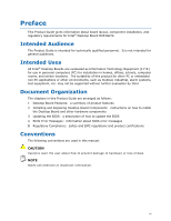
by Intel. Document Organization The chapters in this Product Guide are arranged as follows: 1 Desktop Board Features: a summary of product features 2 Installing and Replacing Desktop Board Components: instructions on how to install the Desktop Board and other hardware components 3 Updating the BIOS - Intel D201GLY2A | Product Guide - Page 4
Megabyte (1,048,576 bytes) Mbit Megabit (1,048,576 bits) MHz Megahertz (one million hertz) Box Contents • Intel Desktop Board • I/O shield • One ATA-66/100 cable • One Serial ATA (SATA) cable • Quick Reference Guide • Configuration and safety labels • Intel® Express Installer driver CD-ROM iv - Intel D201GLY2A | Product Guide - Page 5
...19 Hardware Support 19 Power Connectors 19 Fan Headers 19 +5 V Standby Power Indicator LED 19 LAN Wake Capabilities 20 Wake from USB 21 Wake from PS/2 Keyboard/Mouse 21 PME# Wakeup Support 21 Battery ...21 Real-Time Clock 21 2 Installing and Replacing Desktop Board Components Before You - Intel D201GLY2A | Product Guide - Page 6
D201GLY2 Product Guide Connecting the Front Panel Header 34 Connecting the Chassis Fan 35 Connecting Supply Power Cables 36 Setting the Desktop Board Jumpers 37 Front Panel Audio Header/Jumper Block 37 BIOS Configuration Jumper 38 Clearing Passwords 39 Replacing the Battery 40 3 Updating - Intel D201GLY2A | Product Guide - Page 7
x 12 Power Supply Cable 36 14. Desktop Board Jumpers 37 15. Removing the Battery 44 16. Desktop Board D201GLY2 China RoHS Material Self Declaration Table 57 Tables 1. Feature Summary 9 2. Desktop Boards D201GLY2 Components 12 3. RJ-45 10/100 Ethernet LAN Connector LEDs 16 4. Front Panel Audio - Intel D201GLY2A | Product Guide - Page 8
Intel Desktop Board D201GLY2 Product Guide viii - Intel D201GLY2A | Product Guide - Page 9
the main features of Intel® Desktop Board D201GLY2. Table 1 summarizes the features of the Desktop Board. Table 1. Feature Summary Form Factor Processor Mini-ITX (171.45 millimeters [6.75 inches] x 171.45 millimeters [6.75 inches]) Intel® Celeron® processor Main Memory • One 240-pin SDRAM - Intel D201GLY2A | Product Guide - Page 10
about Desktop Board D201GLY2, including the Technical Product Specification (TPS), BIOS updates, and device drivers, go to: http://support.intel.com/support/motherboards/desktop/ Supported Operating Systems The Desktop Board supports the following operating systems: • Microsoft Windows Vista - Intel D201GLY2A | Product Guide - Page 11
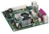
Desktop Board Features Desktop Board Components Figure 1 shows the location of the major components on Desktop Board D201GLY2. Figure 1. Intel Desktop Board D201GLY2 Components 11 - Intel D201GLY2A | Product Guide - Page 12
header Battery BIOS configuration jumper Related Links: Go to the following links for more information about: • Desktop Board D201GLY2 • Audio software and utilities • LAN software and drivers http://www.intel.com/design/motherbd http://support.intel.com/support/motherboards/desktop http://www - Intel D201GLY2A | Product Guide - Page 13
the Serial Presence Detect (SPD) data structure. If your memory modules do not support SPD, you will see a notification to this effect on the screen at power up. The BIOS will attempt to configure the memory controller for normal operation. The Desktop Board has one 240-pin Double Data Rate 2 (DDR2 - Intel D201GLY2A | Product Guide - Page 14
Intel Desktop Board D201GLY2 Product Guide Chipset The chipset used on Desktop Board D201GLY2 consists of the following devices: • SiS662 Graphics and Memory Controller (Northbridge) • SiS964 I/O Controller (Southbridge) Graphics Subsystem The Desktop Board D201GLY2 graphics subsystem features the - Intel D201GLY2A | Product Guide - Page 15
to power headphones or amplified speakers only. Poor audio quality occurs if passive (non-amplified) speakers are connected to this output. Related Links: Go to the following link or pages for more information about: • Audio drivers and utilities http://support.intel.com/support/motherboards/desktop - Intel D201GLY2A | Product Guide - Page 16
Intel Desktop Board D201GLY2 Product Guide LAN Subsystem Software For LAN software and drivers, refer to the D201GLY2 link on Intel's World Wide Web site at: http://support.intel.com/support/motherboards/desktop RJ-45 LAN Connector LEDs Two LEDs are built into the RJ-45 LAN connector located on the - Intel D201GLY2A | Product Guide - Page 17
Desktop Board supports two Serial ATA channels (1.5 Gb/s), connecting one device per channel. Expandability The Desktop Board supports one PCI add-in card. BIOS The BIOS provides the Power-On Self-Test (POST), the BIOS Setup program, the PCI and IDE auto-configuration utilities, and the video BIOS - Intel D201GLY2A | Product Guide - Page 18
Intel Desktop Board D201GLY2 Product Guide IDE Auto Configuration If you install an IDE device (such as a hard drive) in your computer, the autoconfiguration utility in the BIOS automatically detects and configures the device for your computer. You do not need to run the BIOS Setup program after - Intel D201GLY2A | Product Guide - Page 19
system that provides full ACPI support. Hardware Support Power Connectors The Desktop Board has two power connectors. See Figure 13 on page 36 for the location of the power connectors. Fan Headers The Desktop Board has a 3-pin processor fan header and a 3-pin chassis fan header. See Figure 12 on - Intel D201GLY2A | Product Guide - Page 20
the product, and selecting Product Documentation from the left-hand menu: http://support.intel.com/support/motherboards/desktop/ LAN Wake Capabilities CAUTION For LAN wake capabilities, the 5 V standby line for the power supply must be capable of delivering adequate +5 V standby current. Failure to - Intel D201GLY2A | Product Guide - Page 21
PS/2 Keyboard/Mouse PS/2 keyboard/mouse activity wakes the computer from an ACPI S1 state. PME# Wakeup Support When the PME# signal on the PCI bus is asserted, the computer wakes from an ACPI S1 or S5 state. Battery A battery on the Desktop Board keeps the values in CMOS RAM and the clock current - Intel D201GLY2A | Product Guide - Page 22
Intel Desktop Board D201GLY2 Product Guide 22 - Intel D201GLY2A | Product Guide - Page 23
the I/O shield • Install and remove the Desktop Board • Install and remove memory • Connect the IDE cable • Connect the SATA cable • Connect internal headers • Connect chassis fan and power supply cables • Set the BIOS configuration and audio jumpers • Clear passwords • Replace the battery Before - Intel D201GLY2A | Product Guide - Page 24
Intel Desktop Board D201GLY2 Product Guide Installation Precautions When you install and test the Intel Desktop Board, observe all warnings and cautions in the installation instructions. To avoid injury, be careful of: • Sharp pins on connectors or headers • Sharp pins on printed circuit assemblies - Intel D201GLY2A | Product Guide - Page 25
transmissions, protects internal components from dust and foreign objects, and promotes correct airflow within the chassis. Install the I/O shield before installing the Desktop Board in the chassis. Place the shield inside the chassis as shown in Figure 5. Press the shield into place so that it fits - Intel D201GLY2A | Product Guide - Page 26
the power before you open the computer can result in personal injury or equipment damage. Refer to your chassis manual for instructions on installing and removing the Desktop Board. Figure 6 shows the location of the mounting screw holes for Desktop Board D201GLY2. Figure 6. Desktop Board D201GLY2 - Intel D201GLY2A | Product Guide - Page 27
all applicable Intel SDRAM memory specifications, the boards require DIMMs that support the Serial Presence Detect (SPD) data structure. You can access the PC Serial Presence Detect Specification at: http://www.intel.com/technology/memory/ddr/specs/dda18c32_64_128x72ag_a.pdf The Desktop Board has - Intel D201GLY2A | Product Guide - Page 28
Intel Desktop Board D201GLY2 Product Guide 1. Observe the precautions in "Before You Begin" on page 23. 2. Turn off all peripheral devices connected to the computer. Turn off the computer and disconnect the AC power cord. 3. Remove the computer's cover and locate the DIMM socket (see Figure 8). - Intel D201GLY2A | Product Guide - Page 29
and reconnect the AC power cord. Connecting the IDE Cable The IDE cable can connect two drives to the Desktop Board. The cable supports the ATA-100 the cable end with the single connector (blue) to the Intel Desktop Board (Figure 9). 3. Attach the cable end with the two closely spaced connectors (gray - Intel D201GLY2A | Product Guide - Page 30
Intel Desktop Board D201GLY2 Product Guide Figure 9. Connecting the IDE Cable 30 - Intel D201GLY2A | Product Guide - Page 31
(SATA) Cable The SATA cable supports the Serial ATA protocol and connects a single drive to the desktop board. For correct cable function: 1. Observe the precautions in "Before You Begin" on page 23. 2. Attach the locking cable end to the connector on the board (Figure 10, A). 3. Attach the cable - Intel D201GLY2A | Product Guide - Page 32
Intel Desktop Board D201GLY2 Product Guide Connecting Internal Headers Before connecting cables to the internal headers, observe the precautions in "Before You Begin" on page 23. Figure 11 shows the location of the board's internal headers. Item A B C Description Audio Hi-speed USB 2.0 Front panel - Intel D201GLY2A | Product Guide - Page 33
Desktop Board Components Installing a Front Panel Audio Solution Figure 11, A shows the location of the front panel audio header. Table 4 shows the pin assignments for the front panel audio header. Table 4. Front Panel Audio AC power cord. 3. Remove the cover. 4. Remove the front panel audio cable. - Intel D201GLY2A | Product Guide - Page 34
Intel Desktop Board D201GLY2 Product Guide Connecting Hi-Speed USB 2.0 Headers Before connecting the USB Header Signal Names Pin Signal In/Out Description Pin Signal In/Out Description Hard Drive Activity LED Power LED 1 HD_PWR Out Hard disk LED pullup (330 Ω) to +5 V 2 HDR_BLNK_GRN Out - Intel D201GLY2A | Product Guide - Page 35
Installing and Replacing Desktop Board Components Connecting the Chassis Fan Figure 12 shows the location of the chassis fan header. Connect the chassis fan cable to this header. Figure 12. Location of the Chassis Fan Header 35 - Intel D201GLY2A | Product Guide - Page 36
Intel Desktop Board D201GLY2 Product Guide Connecting Power Supply Cables CAUTION Failure to use an appropriate power supply and/or not connecting the 12 V (2 x 2) power connector to the Desktop Board may result in damage to the board or the system may not function properly. Figure 13 shows the - Intel D201GLY2A | Product Guide - Page 37
Desktop Board Components Setting the Desktop Board Jumpers NOTE Always turn off the power and unplug the power cord from the computer before changing a jumper. Moving the jumper with the power on may result in unreliable computer operation. Figure 14. Desktop Board Jumpers Front Panel Audio - Intel D201GLY2A | Product Guide - Page 38
Intel Desktop Board D201GLY2 Product Guide Table 7 describes the two configurations of this header/jumper block. Table 7. Front Panel Audio Header/Jumper Block Jumper Setting 5 and 6 9 and 10 Configuration Audio line out and mic-in signals are routed to the back panel connectors. The back panel - Intel D201GLY2A | Product Guide - Page 39
Desktop Board Components Clearing Passwords This procedure assumes that the board and Setup displays a pop-up screen requesting that you confirm clearing the password. Select Turn off the computer. Disconnect the computer's power cord from the AC power source. 11. Remove the computer cover. 12 - Intel D201GLY2A | Product Guide - Page 40
Intel Desktop Board D201GLY2 Product Guide Replacing the Battery A coin-cell battery (CR2032) powers the real-time clock and CMOS memory. When the computer is not plugged into a wall socket, the battery has an estimated life of three years. When the computer is plugged in, the - Intel D201GLY2A | Product Guide - Page 41
Installing and Replacing Desktop Board Components AVVERTIMENTO Esiste il pericolo di un esplosione se la pila non viene sostituita in modo corretto. Utilizzare solo pile uguali o di tipo equivalente a quelle - Intel D201GLY2A | Product Guide - Page 42
Intel Desktop Board D201GLY2 Product Guide AWAS Risiko letupan wujud jika bateri digantikan dengan jenis yang tidak betul. Bateri sepatutnya dikitar semula jika boleh. Pelupusan bateri terpakai mestilah mematuhi peraturan alam - Intel D201GLY2A | Product Guide - Page 43
Installing and Replacing Desktop Board Components 43 - Intel D201GLY2A | Product Guide - Page 44
Intel Desktop Board D201GLY2 Product Guide To replace the battery, follow these steps: 1. Observe the precautions in "Before You Begin" (see page 23). 2. Turn off all peripheral devices connected to the computer. Disconnect the computer's power cord from the AC power source (wall outlet or power - Intel D201GLY2A | Product Guide - Page 45
of the Intel® Flash Memory Update Utility and the ease of use of Windows-based installation wizards. To update the BIOS with the Intel Express BIOS Update utility: 1. Go to the Intel World Wide Web site: http://support.intel.com/support/motherboards/desktop/ 2. Navigate to the D201GLY2 page, click - Intel D201GLY2A | Product Guide - Page 46
manually update the BIOS. Recovering the BIOS It is unlikely that anything will interrupt the BIOS update; however, if an interruption occurs, the BIOS could be damaged. For more information about recovering the BIOS for desktop board D201GLY2, go to: http://support.intel.com/support/motherboards - Intel D201GLY2A | Product Guide - Page 47
off for 0.5 second; pattern repeats until BIOS update is complete. Video error On-off (0.5 second each) two times, then 3.0 second pause (off) between on-off blink pattern; repeat entire pattern (two on-off blinks and pause) until system is powered off Memory error On-off (0.5 second each) three - Intel D201GLY2A | Product Guide - Page 48
Intel Desktop Board D201GLY2 Product Guide 48 - Intel D201GLY2A | Product Guide - Page 49
(EMC) regulations • Product certifications Safety Standards Desktop Board D201GLY2 complies with the safety standards stated in Table ) Place Battery Marking There is insufficient space on this Desktop Board to provide instructions for replacing and disposing of the Lithium ion coin cell - Intel D201GLY2A | Product Guide - Page 50
Intel Desktop Board D201GLY2 Product Guide European Union Declaration of Conformity Statement We, Intel Corporation, declare under our sole responsibility that the product Intel® Desktop Board D201GLY2 is in conformity with all applicable essential requirements necessary for CE marking, following - Intel D201GLY2A | Product Guide - Page 51
consult http://www.intel.com/intel/other/ehs/product_ecology for the details of this program, including the scope of covered products, available locations, shipping instructions, terms and conditions, etc Intel Product Recycling Program http://www.intel.com/intel/other/ehs/product_ecology 51 - Intel D201GLY2A | Product Guide - Page 52
Intel Desktop Board D201GLY2 Product Guide Deutsch Als Teil von Intels Engagement für den Umweltschutz hat das Unternehmen das Intel Produkt-Recyclingprogramm implementiert, das Einzelhandelskunden von Intel , les instructions d'expédition, les conditions générales, etc http://www.intel.com/in - Intel D201GLY2A | Product Guide - Page 53
produtos cobertos, os locais disponíveis, as instruções de envio, os termos e condições, etc. Russian Intel Intel (Product Recycling Program Intel http://www.intel.com/intel/other/ehs/product_ecology Türkçe Intel, çevre sorumluluğuna bağımlılığının bir parçası olarak, perakende tüketicilerin - Intel D201GLY2A | Product Guide - Page 54
Intel Desktop Board D201GLY2 Product Guide Lead-free 2LI/Pb-free 2LI Board The electronics industry is transitioning to European ppm of lead. Lead-free/Pb-free is a nickname that is often used (or misused) for RoHS-compliant products. In this case, the term "Lead-free/Pb-free" means that lead has - Intel D201GLY2A | Product Guide - Page 55
components in which the Pb concentration level in the Desktop Board substrate and the solder connections from the board to or the components to 0.01% or 100 ppm) by weight of homogeneous material. Desktop Board D201GLY2 complies with these restrictions. China RoHS "China RoHS" is the term - Intel D201GLY2A | Product Guide - Page 56
Intel Desktop Board D201GLY2 Product Guide China RoHS bans the same substances and has the same limits as EU RoHS. However, the China RoHS regulation requires specific product marking and a selfdeclaration of the controlled substances contained in each product. Desktop Board D201GLY2 is a China - Intel D201GLY2A | Product Guide - Page 57
Regulatory Compliance Figure 16. Desktop Board D201GLY2 China RoHS Material Self Declaration Table 57 - Intel D201GLY2A | Product Guide - Page 58
Intel Desktop Board D201GLY2 Product Guide EMC Regulations Desktop Board D201GLY2 complies with the EMC regulations stated in Table 14 when correctly installed in a compatible host environment, it may cause radio interference. Install and use the equipment according to the instruction manual. 58 - Intel D201GLY2A | Product Guide - Page 59
Class B EMC testing and are marked accordingly. Pay close attention to the following when reading the installation instructions for the host chassis, power supply, and other modules: • Product certifications or lack of certifications • External I/O cable shielding and filtering • Mounting, grounding - Intel D201GLY2A | Product Guide - Page 60
Intel Desktop Board D201GLY2 Product Guide Product Certifications Board-Level Certification Markings Desktop Board D201GLY2 has the product CPU-D201GLY2 (B). Taiwan BSMI (Bureau of Standards, Metrology and Inspections) mark. Includes adjacent Intel company number, D33025. Printed wiring board - Intel D201GLY2A | Product Guide - Page 61
Component Certifications Ensure that the chassis and certain components; such as the power supply, peripheral drives, wiring, and cables; are components certified for the country Industry Canada statement at the front of this product guide demonstrates compliance with Canadian EMC regulations. 61
-
 1
1 -
 2
2 -
 3
3 -
 4
4 -
 5
5 -
 6
6 -
 7
7 -
8
-
9
-
10
-
11
-
12
-
13
-
14
-
15
-
16
-
17
-
18
-
19
-
20
-
21
-
22
-
23
-
24
-
25
-
26
-
27
-
28
-
29
-
30
-
31
-
32
-
33
-
34
-
35
-
36
-
37
-
38
-
39
-
40
-
41
-
42
-
43
-
44
-
45
-
46
-
47
-
48
-
49
-
50
-
51
-
52
-
53
-
54
-
55
-
56
-
57
-
58
-
59
-
60
-
61
 |
 |
Intel® Desktop Board D201GLY2
Product Guide
Order Number:
E1776
7
-001