Intel D5400XS Product Guide
Intel D5400XS - Desktop Board Extreme Series Motherboard Manual
 |
UPC - 735858198684
View all Intel D5400XS manuals
Add to My Manuals
Save this manual to your list of manuals |
Intel D5400XS manual content summary:
- Intel D5400XS | Product Guide - Page 1
Intel® Desktop Board D5400XS Product Guide Order Number: E24559-001 - Intel D5400XS | Product Guide - Page 2
Revision -001 Revision History First release of the Intel® Desktop Board D5400XS Product Guide Date January 2008 If an FCC declaration of energy and, if not installed and used in accordance with the instructions, may cause harmful interference to radio communications. However, there is no - Intel D5400XS | Product Guide - Page 3
equipment, etc. may not be supported without further evaluation by Intel. Document Organization The chapters in this Product Guide are arranged as follows: 1 Desktop Board Features: a summary of product features 2 Installing and Replacing Desktop Board Components: instructions on how to install the - Intel D5400XS | Product Guide - Page 4
Intel Desktop Board D5400XS Product Guide Terminology The table below gives descriptions of some common terms used in the product guide. Term Description GB Gigabyte (1,073,741,824 bytes) GHz Gigahertz (one billion hertz) KB Kilobyte (1024 bytes) MB Megabyte (1,048,576 bytes) Mb - Intel D5400XS | Product Guide - Page 5
Contents 1 Desktop Board Features Desktop Board Components 11 Processors ...13 Main Memory...13 Intel® 5400 Chipset 14 Audio Subsystem 14 LAN Subsystem 15 USB 2.0 Support 16 Hard Disk and Optical Disk Drive Support 16 Enhanced IDE Interface 16 Serial ATA 17 Disk Drive Access Indicator 18 - Intel D5400XS | Product Guide - Page 6
Intel Desktop Board D5400XS Product Guide Installing and Removing the Desktop Board 32 Installing a Processor 33 Installing a Processor 33 Installing a Processor Fan Heat Sink 37 Installing an MCH Heat Sink Fan (Optional 38 Installing and Removing Memory 39 Installing DIMMs 39 Removing DIMMs - Intel D5400XS | Product Guide - Page 7
Standby Power Indicator 24 5. Onboard Power and Reset Buttons 26 6. Location of the VR and CPU LEDs 27 7. Installing the I/O Shield 31 8. Desktop Board D5400XS Mounting Screw Hole Locations 32 9. Lift the Socket Lever 33 10. Lift the Load Plate 34 11. Remove the Protective Socket Cover 34 12 - Intel D5400XS | Product Guide - Page 8
Intel Desktop Board D5400XS Product Guide 28. Removing the Battery 62 29. POST Code Indicators 72 30. Desktop Board D5400XS China RoHS Material Self Declaration Table 85 Tables 1. Feature Summary 9 2. Desktop Board D5400XS Components 12 3. LAN Status LEDs 16 4. HD Audio Link Header Signal - Intel D5400XS | Product Guide - Page 9
240-pin, DDR2 SDRAM Fully-Buffered Dual Inline Memory Module (FBDIMM) sockets • Support for 800/667 MHz SDRAM • Support for up to 16 GB of system memory Intel® 5400 Chipset consisting of: • Intel® 5400 Memory Controller Hub (MCH) • Intel® 6321ESB I/O Controller Hub • Support for multiple PCI Express - Intel D5400XS | Product Guide - Page 10
D5400XS Product Guide Table 1. Feature Summary (continued) RAID • Intel® Matrix Storage Technology for the six onboard SATA ports • Marvell* Storage Technology for the two eSATA ports LAN Support Intel , go to the Desktop Board D5400XS page at http://www.intel.com/products/motherboard/ 10 - Intel D5400XS | Product Guide - Page 11
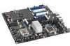
Desktop Board Features Desktop Board Components Figure 1 shows the approximate location of the major components on Desktop Board D5400XS. Figure 1. Desktop Board D5400XS Components 11 - Intel D5400XS | Product Guide - Page 12
Intel Desktop Board D5400XS Product Guide Table 2. Desktop Board D5400XS Components Label A B C D E F G H I J K L M N O P Q R S T U V W X Y Z AA BB CC DD EE FF GG HH II JJ KK Description Auxiliary chassis fan header (4-pin) PCI Express x16 connector 3 PCI Express - Intel D5400XS | Product Guide - Page 13
Links Go to the following page or link for more information about: • Instructions on installing or upgrading the processor, page 33 in Chapter 2 • Supported processors for Desktop Board D5400XS, http://www.intel.com/products/motherboard/ Main Memory NOTE To be fully compliant with all applicable - Intel D5400XS | Product Guide - Page 14
D5400XS Product Guide Related Links Go to the following links or pages for more information about: • FBDIMMs, http://www.intel.com/technology/memory/ • Installing memory, page 39 in Chapter 2 • Recommended memory for Desktop Board D5400XS, http://www.intel.com/products/motherboard/ Intel supports - Intel D5400XS | Product Guide - Page 15
the LAN controller • PCI bus power management Related Links Go to the following link for information about LAN software and drivers: http://www.intel.com/products/motherboard/ Two LEDs are built into the RJ-45 LAN connector located on the back panel (see Figure 2). These LEDs indicate the status of - Intel D5400XS | Product Guide - Page 16
Intel Desktop Board D5400XS Product Guide Table 3 describes the LED states when the board is powered up occurring 10 Mb/s data rate 100 Mb/s data rate 1000 Mb/s data rate USB 2.0 Support The Desktop Board supports up to 10 USB 2.0 ports (six ports routed to back panel connectors and four ports - Intel D5400XS | Product Guide - Page 17
ATA Desktop Board D5400XS supports six onboard Serial ATA (SATA) channels (3.0 Gb/s) via the Intel 6321ESB I/O Controller Hub and two External SATA (eSATA) channels (3.0 Gb/s) via a discrete onboard controller. The six onboard SATA channels provide support the following RAID (Redundant Array of - Intel D5400XS | Product Guide - Page 18
Intel Desktop Board D5400XS Product Guide Disk Drive Access Indicator Desktop Board D5400XS includes a blue LED that lights when either a Legacy I/O Desktop Board D5400XS includes an I/O controller that provides the following legacy I/O features: • Consumer Infrared (CIR) support • Low pin count - Intel D5400XS | Product Guide - Page 19
Board D5400XS provides the SPI) Flash device. The BIOS can be updated by following the instructions on page 63 in Chapter 3. Serial ATA and IDE Auto Configuration device. You can override the auto-configuration options by specifying manual configuration in the BIOS Setup program. PCI and PCI Express* - Intel D5400XS | Product Guide - Page 20
Intel Desktop Board D5400XS Product Guide Hardware Management The hardware management features of Desktop Board D5400XS enable the board to be compatible with the Wired for Management (WfM) specification. The board has several hardware management features including the following: • Fan speed - Intel D5400XS | Product Guide - Page 21
RAM) • +5 V standby power indicator LED • Wake from USB • Power Management Event (PME#) signal wake-up support • WAKE# signal wake-up support Desktop Board D5400XS is also ENERGY STAR capable. Software Support ACPI ACPI gives the operating system direct control over the power management and Plug and - Intel D5400XS | Product Guide - Page 22
Intel Desktop Board D5400XS Product Guide Fan Headers The function/operation of the fans is fan header is wired to a tachometer input of the hardware monitoring and control device. • All fan headers support closed-loop fan control that can adjust the fan speed or switch the fan on or off as needed. - Intel D5400XS | Product Guide - Page 23
(ACPI S3 sleep state) configuration. If the standby current necessary to support multiple wake events from the PCI and/or USB buses exceeds power supply capacity, the Desktop Board may lose register settings stored in memory. Instantly Available PC technology enables the board to enter the ACPI S3 - Intel D5400XS | Product Guide - Page 24
Board D5400XS Product Guide Figure 4. Location of the Standby Power Indicator Related Links For more information on standby current requirements for the Desktop Board, refer to the Technical Product Specification on the Desktop Board D5400XS page at http://www.intel.com/products/motherboard/. 24 - Intel D5400XS | Product Guide - Page 25
wakes from an ACPI S1, S3, S4, or S5 state. WAKE# Signal Wake-up Support When the WAKE# signal on the PCI Express bus is asserted, the computer wakes from an recommendations concerning the new ENERGY STAR requirements: http://www3.intel.com/cd/channel/reseller/asmona/eng/337748.htm. Onboard Power - Intel D5400XS | Product Guide - Page 26
Intel Desktop Board D5400XS Product Guide The power and reset buttons on the front panel are recommended for all other instances of power cycling or resetting the computer. Figure 5. Onboard Power and Reset Buttons 26 - Intel D5400XS | Product Guide - Page 27
Desktop Board Features Onboard VR and CPU LEDs The Desktop board contains a red VR LED and a red CPU LED for each processor as shown in Figure 6). These LEDs indicate the following conditions: • When lit, the VR LEDs (Figure 6, A and D) indicate an elevated temperature in the processor voltage - Intel D5400XS | Product Guide - Page 28
Intel Desktop Board D5400XS Product Guide Speaker A speaker mounted on the Desktop Board provides audible error code (beep CMOS RAM and the clock current when the computer is turned off. Go to page 57 for instructions on how to replace the battery. Real-Time Clock The Desktop Board has a time-of-day - Intel D5400XS | Product Guide - Page 29
how to: • Install the I/O shield • Install and remove the Desktop Board • Install a processor • Install an MCH heat sink fan • Install and remove memory • Install and remove a PCI Express x16 card • Connect the IDE and Serial ATA cables • Connect to the internal headers and connectors • Connect to - Intel D5400XS | Product Guide - Page 30
D5400XS Product Guide Installation Precautions When you install or test the Intel Desktop Board, observe all warnings and cautions in the installation instructions . Observe all warnings and cautions that instruct you to refer computer servicing to qualified technical personnel. Prevent Power Supply - Intel D5400XS | Product Guide - Page 31
%20v3-61.pdf). For a list of recommended chassis and power supplies for this Desktop Board, refer to the Intel Desktop Board D5400XS page at http://support.intel.com/support/motherboards/desktop/. Install the I/O shield before installing the Desktop Board in the chassis. Place the shield inside the - Intel D5400XS | Product Guide - Page 32
Intel Desktop Board D5400XS Product Guide Installing and Removing the Desktop Board CAUTION Only qualified the computer can result in personal injury or equipment damage. Refer to your chassis manual for instructions on installing and removing the Desktop Board. CAUTION To ensure that you do not - Intel D5400XS | Product Guide - Page 33
Figure 4 on page 24). Failure to follow these precautions could result in damage to the processor and the board. To install a processor, follow these instructions: 1. Observe the precautions in "Before You Begin" on page 29. 2. Open the socket lever by pushing the lever down and away from the socket - Intel D5400XS | Product Guide - Page 34
Intel Desktop Board D5400XS Product Guide 3. Lift the load plate (Figure 10, A). Do not touch the socket contacts (Figure 10, B). Figure 10. Lift the Load Plate 4. Remove the plastic protective socket - Intel D5400XS | Product Guide - Page 35
Installing and Replacing Desktop Board Components 5. Remove the processor from the protective processor cover. Hold the processor only at the edges, being careful not to touch the bottom of the processor (see Figure 12). Do not discard the protective processor cover. Always replace the processor - Intel D5400XS | Product Guide - Page 36
Intel Desktop Board D5400XS Product Guide 7. Pressing down on the load plate (Figure 14, A), close and engage the socket lever (Figure 14, B). Figure 14. Close the Load Plate 36 - Intel D5400XS | Product Guide - Page 37
though this board has LGA771 processor sockets. NOTE For a list of recommended heat sinks for Desktop Board D5400XS, refer to the Desktop Board D5400XS page at http://www.intel.com/products/motherboard/. After you install the fan heat sinks, connect the fan power connectors to the 4-pin processor - Intel D5400XS | Product Guide - Page 38
Intel Desktop Board D5400XS Product Guide Installing an MCH Heat Sink Fan (Optional An MCH heat sink fan is not included with Desktop Board D5400XS and must be purchased separately. To install an MCH heat sink fan, follow these instructions: 1. Observe the precautions in "Before You Begin" on page - Intel D5400XS | Product Guide - Page 39
Installing and Replacing Desktop Board Components Installing and Removing Memory Desktop board D5400XS has four 240-pin FBDIMM sockets providing quad-channel memory support with one DIMM per channel. The sockets are keyed so that they will accept only FBDIMMs. Installing DIMMs To install a DIMM, - Intel D5400XS | Product Guide - Page 40
Intel Desktop Board D5400XS Product Guide 6. Position the DIMM above the socket. Align the small notch at the bottom edge of the DIMM with the key in the socket (see inset - Intel D5400XS | Product Guide - Page 41
a DIMM cooling fan be installed on Desktop Board D5400XS to ensure proper memory operation. Use the board's 3-pin DIMM fan header D5400XS and must be purchased separately. A list of compatible clip-on fans is available on the Desktop Board D5400XS page at http://www.intel.com/products/motherboard - Intel D5400XS | Product Guide - Page 42
Intel Desktop Board D5400XS Product Guide Installing and Removing PCI Express x16 Cards CAUTION Desktop Board components and/or traces may be damaged. Installing a PCI Express x16 Card Follow these instructions to install a PCI Express x16 card: 1. Observe the precautions in "Before You Begin" on - Intel D5400XS | Product Guide - Page 43
Installing and Replacing Desktop Board Components Removing a PCI Express x16 Card Follow these instructions to remove a PCI Express x16 card from a connector: 1. Observe the precautions in "Before You Begin" on page 29. 2. Remove the screw (Figure 20, A) that secures - Intel D5400XS | Product Guide - Page 44
Desktop Board D5400XS Product Guide Installing Multiple Graphics Cards The Desktop Board supports technology that allows you to install linked PCI Express x16 graphics cards. When installing multiple graphics cards in the PCI Express x16 connectors, refer to the card manufacturer's instructions to - Intel D5400XS | Product Guide - Page 45
Installing and Replacing Desktop Board Components Figure 21. Connecting the IDE Cable 45 - Intel D5400XS | Product Guide - Page 46
Intel Desktop Board D5400XS Product Guide Connecting the SATA Cables The included SATA cables support the SATA protocol. Each cable can be used to connect one internal SATA drive to the Desktop Board. For correct cable function: 1. Observe the precautions - Intel D5400XS | Product Guide - Page 47
precautions in "Before You Begin" on page 29. Figure 23 shows the location of the internal headers and connectors on Intel Desktop Board D5400XS. Item Description A HD Audio Link B S/PDIF C Front panel audio D IEEE 1394a E Front panel Item Description F USB 2.0 (2) G Front panel CIR - Intel D5400XS | Product Guide - Page 48
Intel Desktop Board D5400XS Product Guide HD Audio Link Header Figure 23, A shows the location of the HD Audio Link header. Table 4 shows the pin assignments and signal names for the - Intel D5400XS | Product Guide - Page 49
Installing and Replacing Desktop Board Components Front Panel Audio Header Figure 23, C shows the location of the front panel audio header. Table 6 shows the pin assignments and signal names for the front panel audio header. Table 6. Front Panel Audio Header Signal Names Pin Signal Name 1 PORT - Intel D5400XS | Product Guide - Page 50
Intel Desktop Board D5400XS Product Guide USB 2.0 Headers Figure 23, F shows the location of the USB 2.0 headers. Table 9 shows the pin assignments and signal names for each USB 2.0 header. Each USB - Intel D5400XS | Product Guide - Page 51
Installing and Replacing Desktop Board Components Table 10. Front Panel CIR Receiver (Input) Header Signal Names Pin Signal Name 1 Ground 3 No Connection 5 +5 V Standby 7 Key (no pin) Pin Signal Name 2 LED 4 Learn-In 6 Vcc 8 CIR Input Table 11. Back Panel CIR Header Emitter ( - Intel D5400XS | Product Guide - Page 52
Desktop Board D5400XS Product Guide Connecting to the Flexible Audio System After installing the IDT* audio driver from the Intel® Express Installer DVD-ROM, the multi-channel audio feature can be enabled. Figure 24 shows the back panel audio connectors. The default connector assignments are - Intel D5400XS | Product Guide - Page 53
Installing and Replacing Desktop Board Components Connecting Chassis Fan and Power Supply Cables Connecting Chassis Fan Cables Connect chassis fan cables to the 3-pin and 4-pin chassis fan headers on the Desktop Board. Figure 25 shows the location of the chassis fan headers. Figure 25. Location of - Intel D5400XS | Product Guide - Page 54
Intel Desktop Board D5400XS Product Guide Connecting Power Supply Cables CAUTION Failure to use an appropriate power supply and/or not connecting the 12 V (2 x 4 pin) power connectors to the Desktop Board - Intel D5400XS | Product Guide - Page 55
Installing and Replacing Desktop Board Components 1. Observe the precautions in "Before You Begin" on page 29. 2. Connect the 12 V processor core voltage power supply cables to the 2 x 4 pin connectors. Make sure to connect one supply cable for each installed processor. 3. If necessary, connect the - Intel D5400XS | Product Guide - Page 56
Intel Desktop Board D5400XS Product Guide The three-pin BIOS jumper block enables all board configurations to be done in the BIOS Setup program. Table 13 shows the jumper settings for - Intel D5400XS | Product Guide - Page 57
the cover, plug in the computer, and turn on the computer. Replacing the Battery A coin-cell battery (CR2032) powers the real-time clock and CMOS memory. When the computer is not plugged into a wall socket, the battery has an estimated life of three years. When the computer is plugged in, the - Intel D5400XS | Product Guide - Page 58
Intel Desktop Board D5400XS Product Guide VARO Räjähdysvaara, jos pariston tyyppi on väärä. Paristot on kierrätettävä, jos se on mahdollista. Käytetyt paristot on hävitettävä paikallisten ympäristömääräysten mukaisesti. VORSICHT Bei - Intel D5400XS | Product Guide - Page 59
Installing and Replacing Desktop Board Components VIGYÁZAT Ha a telepet nem a megfelelő típusú telepre cseréli, az felrobbanhat. A telepeket lehetőség szerint újra kell hasznosítani. A használt telepeket a helyi környezetvédelmi előírásoknak megfelelően kell kiselejtezni. AWAS Risiko letupan - Intel D5400XS | Product Guide - Page 60
Intel Desktop Board D5400XS Product Guide POZOR Zamenjava baterije z baterijo drugačnega tipa lahko povzroči eksplozijo. Če je mogoče, baterije reciklirajte. Rabljene baterije zavrzite v skladu z lokalnimi okoljevarstvenimi predpisi. . UYARI Yanlış türde pil - Intel D5400XS | Product Guide - Page 61
Installing and Replacing Desktop Board Components 61 - Intel D5400XS | Product Guide - Page 62
Intel Desktop Board D5400XS Product Guide To replace the battery, follow these steps: 1. Observe the precautions in "Before You Begin" (see page 29). 2. Turn off all peripheral devices connected to the - Intel D5400XS | Product Guide - Page 63
of the Intel® Flash Memory Update Utility and the ease of use of Windows-based installation wizards. To update the BIOS with the Intel Express BIOS Update utility: 1. Go to the Intel World Wide Web site: http://support.intel.com/support/motherboards/desktop/ 2. Navigate to the D5400XS page, click - Intel D5400XS | Product Guide - Page 64
Toolkit Configuration File (optional) • Intel Flash Memory Update Utility You can obtain either of these files through your computer supplier or by navigating to the Desktop Board D5400XS page on the Intel World Wide Web site at http://support.intel.com/support/motherboards/desktop. Navigate to the - Intel D5400XS | Product Guide - Page 65
USB flash drive or other bootable USB media. The Iflash Memory update utility allows you to: • Update the BIOS and Intel Management Engine in flash memory • Update the language section of the BIOS NOTE Review the instructions distributed with the update utility before attempting a BIOS update. 65 - Intel D5400XS | Product Guide - Page 66
Intel Desktop Board D5400XS Product Guide to the USB device. 3. Manually run the IFLASH.EXE file from the USB device and manually update the BIOS. Recovering the BIOS the Intel Desktop Board BIOS or recovering from a BIOS update failure, go to http://support.intel.com/support/motherboards/desktop/ - Intel D5400XS | Product Guide - Page 67
the Power-On-Self-Test (POST) memory tests begin. 3. Go to Advanced Drive Configuration Configure SATA as; ensure that RAID is selected. 4. Then save your settings by pressing . Creating Your RAID Set 1. Upon re-boot, you will see the following Intel Matrix Storage Manager option ROM status - Intel D5400XS | Product Guide - Page 68
after downloading it from the Desktop Board D5400XS page at http://www.intel.com/products/motherboard/. The Intel Matrix Storage Console software can be used to manage the RAID configuration. Setting Up a "RAID Ready" System The Intel Matrix Storage Technology Console software offers the flexibility - Intel D5400XS | Product Guide - Page 69
of Windows Setup, press to install a third-party SCSI or RAID driver. When prompted, insert the diskette that contains the Marvell Storage Technology RAID Driver in a USB floppy disk drive. Refer to http://support.microsoft.com/kb/916196/en-us for information on selecting a compatible USB - Intel D5400XS | Product Guide - Page 70
Intel Desktop Board D5400XS Product Guide 70 - Intel D5400XS | Product Guide - Page 71
and Indicators Desktop Board D5400XS reports POST errors in three codes. Table 14. Beep Codes Beep 3 Siren Description No memory Processor overheat (on reboot) BIOS Error Messages When a recoverable BIOS displays an error message describing the problem. Table 15 gives an explanation of the - Intel D5400XS | Product Guide - Page 72
Intel Desktop Board D5400XS Product Guide Port 80h POST Codes During the POST, the BIOS generates diagnostic progress codes (POST codes) to I/O port 80h. If the POST fails, execution stops and - Intel D5400XS | Product Guide - Page 73
21 Initializing a chipset component Memory 22 Reading SPD from memory DIMMs 23 Detecting presence of memory DIMMs 24 Programming timing parameters in the memory controller and the DIMMs 25 Configuring memory 26 Optimizing memory settings 27 Initializing memory, such as ECC init 29 - Intel D5400XS | Product Guide - Page 74
D5400XS Product Guide Table 16. Port 80h POST Codes (continued) POST Code Description of POST Operation Keyboard (USB) 90 Resetting the keyboard 91 Disabling the keyboard 92 Detecting presence of a keyboard 93 Enabling the keyboard 94 Clearing the keyboard input buffer 95 Instructing - Intel D5400XS | Product Guide - Page 75
( ) has been called F9 EFI runtime service SetVirtualAddressMap( ) has been called FA EFI runtime service ResetSystem( ) has been called PEIMs/Recovery/Wake 30 Wake from S3 31 Crisis Recovery has initiated by software (corrupt Flash memory) 34 Loading the recovery capsule 35 Handing - Intel D5400XS | Product Guide - Page 76
Intel Desktop Board D5400XS Product Guide 76 - Intel D5400XS | Product Guide - Page 77
EMC) regulations • Product certifications Safety Standards Desktop Board D5400XS complies with the safety standards stated in Table 17 when Battery Marking There is insufficient space on this Desktop Board to provide instructions for replacing and disposing of the Lithium ion coin cell battery. For - Intel D5400XS | Product Guide - Page 78
Intel Desktop Board D5400XS Product Guide European Union Declaration of Conformity Statement We, Intel Corporation, declare under our sole responsibility that the product Intel® Desktop Board D5400XS is in conformity with all applicable essential requirements necessary for CE marking, following the - Intel D5400XS | Product Guide - Page 79
consult http://www.intel.com/intel/other/ehs/product_ecology for the details of this program, including the scope of covered products, available locations, shipping instructions, terms and conditions, etc Intel Product Recycling Program http://www.intel.com/intel/other/ehs/product_ecology 79 - Intel D5400XS | Product Guide - Page 80
Intel Desktop Board D5400XS Product Guide Deutsch Als Teil von Intels Engagement für den Umweltschutz hat das Unternehmen das Intel Produkt-Recyclingprogramm implementiert, das Einzelhandelskunden von Intel , les instructions d'expédition, les conditions générales, etc. http://www.intel.com/in - Intel D5400XS | Product Guide - Page 81
produtos cobertos, os locais disponíveis, as instruções de envio, os termos e condições, etc. Russian Intel Intel (Product Recycling Program Intel http://www.intel.com/intel/other/ehs/product_ecology Türkçe Intel, çevre sorumluluğuna bağımlılığının bir parçası olarak, perakende tüketicilerin - Intel D5400XS | Product Guide - Page 82
Intel Desktop Board D5400XS Product Guide Lead-free 2LI/Pb-free 2LI Board The electronics is acceptable because of the RoHS "flip chip" or "die bump" interconnect exemption. Desktop Board D5400XS is a lead-free second level interconnect product. Table 18 shows the lead-free second level interconnect - Intel D5400XS | Product Guide - Page 83
maximum concentrations allowed are 0.1% or 1000 ppm (except for cadmium, which is limited to 0.01% or 100 ppm) by weight of homogeneous material. Desktop Board D5400XS complies with these restrictions. 83 - Intel D5400XS | Product Guide - Page 84
Intel Desktop Board D5400XS Product Guide China RoHS "China RoHS" is the term used by industry generally to describe legislation implemented by the Ministry of Information Industry (MII) in the People's - Intel D5400XS | Product Guide - Page 85
Regulatory Compliance Figure 30. Desktop Board D5400XS China RoHS Material Self Declaration Table 85 - Intel D5400XS | Product Guide - Page 86
Intel Desktop Board D5400XS Product Guide EMC Regulations Desktop Board D5400XS complies with the EMC regulations stated in Table 20 when correctly installed in a compatible host environment, it may cause radio interference. Install and use the equipment according to the instruction manual. 86 - Intel D5400XS | Product Guide - Page 87
, as applicable, have passed Class B EMC testing and are marked accordingly. Pay close attention to the following when reading the installation instructions for the host chassis, power supply, and other modules: • Product certifications or lack of certifications • External I/O cable shielding and - Intel D5400XS | Product Guide - Page 88
Intel Desktop Board D5400XS Product Guide Product Certifications Board-Level Certification Markings Desktop Board D5400XS has the product certification markings shown in Table 21. Table 21. Product Certification Markings Description UL joint US/Canada Recognized Component mark. Includes adjacent - Intel D5400XS | Product Guide - Page 89
Canada A nationally recognized certification mark such as CSA or cUL signifies compliance with safety requirements. The Industry Canada statement at the front of this product guide demonstrates compliance with Canadian EMC regulations. 89 - Intel D5400XS | Product Guide - Page 90
Intel Desktop Board D5400XS Product Guide 90
-
 1
1 -
 2
2 -
 3
3 -
 4
4 -
 5
5 -
 6
6 -
 7
7 -
8
-
9
-
10
-
11
-
12
-
13
-
14
-
15
-
16
-
17
-
18
-
19
-
20
-
21
-
22
-
23
-
24
-
25
-
26
-
27
-
28
-
29
-
30
-
31
-
32
-
33
-
34
-
35
-
36
-
37
-
38
-
39
-
40
-
41
-
42
-
43
-
44
-
45
-
46
-
47
-
48
-
49
-
50
-
51
-
52
-
53
-
54
-
55
-
56
-
57
-
58
-
59
-
60
-
61
-
62
-
63
-
64
-
65
-
66
-
67
-
68
-
69
-
70
-
71
-
72
-
73
-
74
-
75
-
76
-
77
-
78
-
79
-
80
-
81
-
82
-
83
-
84
-
85
-
86
-
87
-
88
-
89
-
90
 |
 |
Intel
®
Desktop Board D5400XS
Product Guide
Order Number:
E24559-001