Intel D845GLAD Product Guide - Page 10
Processor, CAUTION - processor upgrade
 |
UPC - 735858153386
View all Intel D845GLAD manuals
Add to My Manuals
Save this manual to your list of manuals |
Page 10 highlights
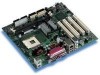
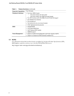
Intel Desktop Boards D845GLLY and D845GLAD Product Guide Processor CAUTION Failure to use an ATX12V or SFX-12V power supply, or not connecting the additional power supply lead to Desktop Board D845GLLY or D845GLAD may result in damage to the Intel desktop board and/or power supply. Desktop Boards D845GLLY and D845GLAD support a single Intel Pentium 4 processor or Intel Celeron processor. Processors are not included with the Intel desktop board and must be purchased separately. The processor connects to the Intel desktop board through the mPGA-478-pin socket. The Intel Pentium 4 processor or Intel Celeron processor may be removed and replaced to accommodate supported higher speed processors. Desktop Boards D845GLLY and D845GLAD support the processors listed in Table 2. Table 2. Processors Supported by the Desktop Board Type Designation FSB Frequency Intel Pentium 4 processor on .13 micron 2.40, 2.20, 2A, 1.80A, and 400 MHz process in an mPGA-478 package 1.60A GHz Intel Pentium 4 processor on .18 micron 2, 1.90, 1.80, 1.70, 1.60, process in an mPGA-478 package and 1.50 GHz 400 MHz Intel Celeron processor in an mPGA-478 1.8 and 1.7 GHz package 400 MHz L2 Cache 512 KB 256 KB 128 KB For the latest information on processor support for Desktop Boards D845GLLY and D845GLAD, refer to the Intel World Wide Web site at: http://support.intel.com/support/motherboards/desktop/ For instructions on installing or upgrading the processor, see Chapter 2 on page 19. Desktop Boards D845GLLY and D845GLAD require an ATX12V or SFX-12V compliant power supply to function according to Intel desktop board specifications. Both desktop boards have two 12 V compliant power supply connectors that are needed to provide extra power to the Intel 845GL chipset and Intel Pentium 4 processor. Items A and E in Figure 14 on page 62 show the two power connector locations. 10
-
 1
1 -
2
-
3
-
4
-
 5
5 -
 6
6 -
 7
7 -
 8
8 -
 9
9 -
 10
10 -
 11
11 -
 12
12 -
 13
13 -
 14
14 -
 15
15 -
16
-
17
-
18
-
19
-
20
-
21
-
22
-
23
-
24
-
25
-
26
-
27
-
28
-
29
-
30
-
31
-
32
-
33
-
34
-
35
-
36
-
37
-
38
-
39
-
40
-
41
-
42
-
43
-
44
-
45
-
46
-
47
-
48
-
49
-
50
-
51
-
52
-
53
-
54
-
55
-
56
-
57
-
58
-
59
-
60
-
61
-
62
-
63
-
64
-
65
-
66
-
67
-
68
-
69
-
70
-
71
-
72
-
73
-
74
-
75
-
76
 |
 |