Intel D845GLAD Product Guide - Page 26
Connecting the Front Panel Header, Setting the Jumper Blocks - bios update
 |
UPC - 735858153386
View all Intel D845GLAD manuals
Add to My Manuals
Save this manual to your list of manuals |
Page 26 highlights
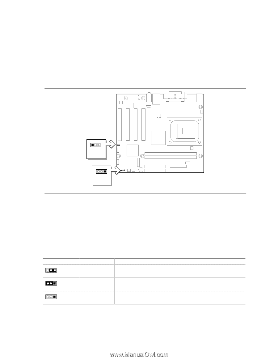
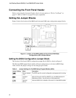
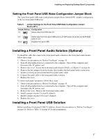
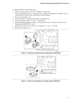
Intel Desktop Boards D845GLLY and D845GLAD Product Guide Connecting the Front Panel Header Before connecting the front panel header, observe the precautions in "Before You Begin" on page 19. Refer to Table 32 on page 65 for pin assignments. Setting the Jumper Blocks Figure 9 shows the location of the BIOS and front panel USB wake configuration jumper blocks. 13 J9F1 31 J9H2 OM13687 Figure 9. Location of the BIOS (J9H2) and Front Panel USB Wake Configuration (J9F1) Jumper Blocks Setting the BIOS Configuration Jumper Block The location of the board's BIOS configuration jumper block (J9H2) is shown in Figure 9. The three-pin BIOS jumper block enables all board configurations to be done in BIOS Setup. Table 4 shows the jumper settings for the Setup program modes. Table 4. Jumper Settings for the BIOS Setup Program Modes (J9H2) Jumper Setting 31 Mode Normal (default) (1-2) Description The BIOS uses the current configuration and passwords for booting. 31 Configure (2-3) After the Power-On Self-Test (POST) runs, the BIOS displays the Maintenance Menu. Use this menu to clear passwords. 31 Recovery (None) Recovers BIOS from a diskette in the event of a failed BIOS update. 26
-
 1
1 -
2
-
3
-
4
-
5
-
6
-
7
-
8
-
9
-
10
-
11
-
12
-
13
-
14
-
15
-
16
-
17
-
18
-
19
-
20
-
 21
21 -
 22
22 -
 23
23 -
 24
24 -
 25
25 -
 26
26 -
 27
27 -
 28
28 -
 29
29 -
 30
30 -
 31
31 -
32
-
33
-
34
-
35
-
36
-
37
-
38
-
39
-
40
-
41
-
42
-
43
-
44
-
45
-
46
-
47
-
48
-
49
-
50
-
51
-
52
-
53
-
54
-
55
-
56
-
57
-
58
-
59
-
60
-
61
-
62
-
63
-
64
-
65
-
66
-
67
-
68
-
69
-
70
-
71
-
72
-
73
-
74
-
75
-
76
 |
 |