Intel D845PESV Product Guide
Intel D845PESV - P4 Socket 478 ATX Motherboard Manual
 |
UPC - 735858156738
View all Intel D845PESV manuals
Add to My Manuals
Save this manual to your list of manuals |
Intel D845PESV manual content summary:
- Intel D845PESV | Product Guide - Page 1
Intel® Desktop Board D845PESV Product Guide Order Number: A99406-002 - Intel D845PESV | Product Guide - Page 2
First release of the Intel® Desktop Board D845PESV Product Guide. Second release of the Intel Desktop Board D845PESV Product Guide. Date July 2002 August and, if not installed and used in accordance with the instructions, may cause harmful interference to radio communications. However, there - Intel D845PESV | Product Guide - Page 3
...9 Processor ...10 Main Memory ...11 Intel® 845PE Chipset...12 Intel® 82845PE Memory Controller Hub (MCH 12 Intel® 82801DB I/O Controller Hub (ICH4 12 Firmware Hub (FWH 12 Input/Output (I/O) Controller 13 Audio Subsystem ...13 LAN Subsystem (Optional 13 LAN Subsystem Software 13 RJ-45 LAN - Intel D845PESV | Product Guide - Page 4
Power Cables 33 Setting the BIOS Configuration Jumper Block 34 Clearing Passwords ...35 Replacing the Battery ...36 3 Updating the BIOS Updating the BIOS with the Intel® Express BIOS Update Utility 39 Updating the BIOS with the Intel® Flash Memory Update Utility 40 Obtaining the BIOS Update - Intel D845PESV | Product Guide - Page 5
Instructions...77 Ensure Electromagnetic Compatibility (EMC) Compliance 77 Chassis and Component Certifications 78 Prevent Power Supply Overload 78 Place Battery Marking 78 Use Only for Intended Applications 78 Figures 1. Desktop Board D845PESV Components 9 2. Location of Standby Power - Intel D845PESV | Product Guide - Page 6
Intel Desktop Boards D845PESV Product Guide Tables 1. Feature Summary ...7 2. Supported Processors 10 3. RJ-45 LAN Connector LEDs 14 4. Front Panel Header (J9G1 31 5. Front Panel Audio Header Signal Names (J8A1 31 6. Front Panel USB 2.0 Header (J9F1 32 7. Jumper Settings for the BIOS Setup - Intel D845PESV | Product Guide - Page 7
1 describes the major features of Intel® Desktop Board D845PESV. Table 1. Feature Summary Form Factor Processor Memory Chipset I/O Control Audio LAN (optional) • ATX at 12.0 inches by 8.2 inches Support for: • 533/400 MHz front side bus (FSB) Intel® Pentium® 4 processor in an mPGA-478 socket - Intel D845PESV | Product Guide - Page 8
connectors - One AGP connector BIOS • Intel/AMI BIOS • 4 Mbit symmetrical flash memory • Support for SMBIOS Power Management • Support for Advanced Configuration and Power Interface (ACPI) • Suspend to RAM (STR) support • Wake on USB, PCI, RS-232, PS/2, LAN, and front panel Hardware Management - Intel D845PESV | Product Guide - Page 9
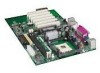
power/sleep LED header J Processor fan connector K DIMM sockets X Front panel header Y Intel® ICH4 L I/O controller Z Front panel USB 2.0 header M Main power connector AA AGP connector N Diskette drive connector BB PCI bus add-in card connectors Figure 1. Desktop Board D845PESV Components - Intel D845PESV | Product Guide - Page 10
on processor support for Desktop Board D845PESV, refer to the Intel World Wide Web site at: http://support.intel.com/support/motherboards/desktop/ For instructions on installing or upgrading the processor, see Chapter 2 on page 21. Desktop Board D845PESV requires an ATX12V compliant power supply to - Intel D845PESV | Product Guide - Page 11
Detect (SPD) data structure. If your memory modules do not support SPD, you will see a notification to this effect on the screen at power up. The BIOS will attempt to configure the memory controller for normal operation. Desktop Board D845PESV supports system memory as defined below: • Up to two - Intel D845PESV | Product Guide - Page 12
(ICH4) with AHA bus • Firmware Hub (FWH) Intel® 82845PE Memory Controller Hub (MCH) The MCH provides the processor, system memory, AGP, and hub interfaces in the Intel 845PE chipset platform. Features on Desktop Board D845PESV include: • Single processor support with 533 MHz or 400 MHz data transfer - Intel D845PESV | Product Guide - Page 13
to power either headphones or amplified speakers only. Poor audio quality may occur if passive (non-amplified) speakers are connected to this output. Audio drivers and utilities are available from Intel's World Wide Web site: http://support.intel.com/support/motherboards/desktop/ LAN Subsystem - Intel D845PESV | Product Guide - Page 14
Intel Desktop Board D845PESV Product Guide RJ-45 LAN Connector LEDs Two LEDs are built into the RJ-45 LAN connector. Table 3 describes the LED states when the board is powered up and the LAN subsystem is operating. Table 3. RJ-45 LAN Connector LEDs LED Color LED State Indicates Green Off 10 - Intel D845PESV | Product Guide - Page 15
with graphical display devices. The AGP connector supports 1.5 V AGP 4X and 2X add-in cards. BIOS The BIOS provides the Power-On Self-Test (POST), the BIOS Setup program, the PCI and IDE auto-configuration utilities, and the video BIOS. The BIOS is stored in the Firmware Hub. The BIOS can be updated - Intel D845PESV | Product Guide - Page 16
. The use of ACPI with Desktop Board D845PESV requires an operating system that provides full ACPI support. Suspend to RAM (Instantly Available PC Technology) CAUTION For Instantly Available PC technology, the 5 V standby line for the power supply must be capable of delivering adequate +5 V standby - Intel D845PESV | Product Guide - Page 17
necessary to support multiple wake events from the PCI and/or USB buses exceeds power supply capacity, the Intel desktop board may lose register settings stored in memory. For more information on standby current requirements for this desktop board, refer to the Technical Product Specification (TPS - Intel D845PESV | Product Guide - Page 18
D845PESV Product Guide Fan Connectors Desktop Board D845PESV has two chassis fan connectors and one processor fan connector. See Figure 11 on page 33 for the location of the fan connectors. Fan Speed Control (Intel® Precision Cooling) Intel of a USB peripheral that supports Wake from USB. Wake from - Intel D845PESV | Product Guide - Page 19
Desktop Board Features Battery A battery on the Intel desktop board keeps the values in CMOS RAM and the clock current when the computer is turned off. See Chapter 2 starting on page 21 for instructions on how to replace the battery. Real-Time Clock Desktop Board D845PESV has a time-of-day clock and - Intel D845PESV | Product Guide - Page 20
Intel Desktop Board D845PESV Product Guide 20 - Intel D845PESV | Product Guide - Page 21
and remove a processor • Install and remove memory • Install and remove an AGP card • Connect the IDE cable • Connect the front panel header • Install the front panel audio solution • Install the front panel USB solution • Connect fans • Connect power cables • Set the BIOS configuration jumper block - Intel D845PESV | Product Guide - Page 22
Desktop Board D845PESV Product Guide Installing the I/O Shield The Intel desktop board comes with an I/O shield. When installed in the chassis, the shield blocks radio frequency transmissions, protects internal components from dust and foreign objects, - Intel D845PESV | Product Guide - Page 23
and Removing the Desktop Board Refer to your chassis manual for instructions on installing and removing the Intel desktop board. WARNING Only qualified technical personnel should do this procedure. Disconnect the computer from its power source before performing the procedures described here. Failure - Intel D845PESV | Product Guide - Page 24
Board D845PESV has an integrated processor fan heat sink retention mechanism (RM). For instructions on how to install the processor fan heat sink to the integrated processor fan heat sink RM, refer to the boxed processor manual or the Intel World Wide Web site at: http://support.intel.com/support - Intel D845PESV | Product Guide - Page 25
Heat Sink Cable to the Processor Fan Connector Removing the Processor For instruction on how to remove the processor fan heat sink and processor, refer to the processor installation manual or the Intel World Wide Web site at: http://support.intel.com/support/processors/pentium4/intnotes478.htm 25 - Intel D845PESV | Product Guide - Page 26
with all applicable Intel SDRAM memory specifications, the board requires DIMMs that support the Serial Presence Detect (SPD) data structure. You can access the PC Serial Presence Detect Specification at: http://www.intel.com/technology/memory/pcsdram/spec/ Desktop Board D845PESV has two 184 - Intel D845PESV | Product Guide - Page 27
11. Replace the computer's cover and reconnect the AC power cord. Removing DIMMs To remove a memory module, follow these steps: 1. Observe the precautions in over-current protection of the power supply, certain board components and/or traces may be damaged. The AGP connector supports 1.5 V 4X and 2X - Intel D845PESV | Product Guide - Page 28
Intel Desktop Board D845PESV Product Guide Installing an AGP Card Follow these instructions to install an AGP card: 1. metal bracket to the chassis back panel with a screw. Removing the AGP Card Follow these instructions to remove the AGP card from the RM: 1. Observe the precautions in "Before You - Intel D845PESV | Product Guide - Page 29
Installing and Replacing Desktop Board Components Connecting the IDE Cable The Intel® boxed desktop board package includes two IDE cables. Either cable can connect two drives to the desktop board. The cables supports the Ultra DMA-33 and ATA-66/100 transfer protocols. Figure 9 shows the correct - Intel D845PESV | Product Guide - Page 30
Intel Desktop Board D845PESV Product Guide Connecting Front Panel Headers Figure 10 shows the location of the front panel headers. 1 2 3 4 A5 6 7 9 10 1 2 3 4 B5 6 7 8 10 12 HD LED Reset No Connection Power LED On C Item A B C D Description Front panel audio Front panel USB - Intel D845PESV | Product Guide - Page 31
Panel Header (J9G1) Pin Signal In/Out Description Hard Drive Activity LED Pin Signal In/Out Description Power LED 1 HD_PWR 3 HDA# Out Hard disk LED . Turn off the computer and disconnect the AC power cord. 3. Remove the cover. 4. Locate the front panel audio header (J8A1), see Figure 10, A on - Intel D845PESV | Product Guide - Page 32
Intel Desktop Board D845PESV Product Guide To restore back panel operations, follow these steps: 1. Observe the precautions in "Before You Begin" on page 21. 2. Turn off all peripheral devices connected to the computer. Turn off the computer and disconnect the AC power cord. 3. Remove the cover. 4. - Intel D845PESV | Product Guide - Page 33
to the processor fan connector on the board. Connect the chassis fan cables to the board fan connectors. See Figure 11 for fan locations. Connecting Power Cables CAUTION Failure to use an ATX12V power supply, or not connecting the additional power supply lead to Desktop Board D845PESV may result - Intel D845PESV | Product Guide - Page 34
Intel Desktop Board D845PESV Product Guide Setting the BIOS Configuration Jumper Block CAUTION Always turn off the power and unplug the power cord from the computer before changing the jumper. Moving the jumper with the power on may result in unreliable computer operation. The location of the - Intel D845PESV | Product Guide - Page 35
confirm clearing the password. Select Yes and press . Setup displays the maintenance menu again. 9. Press to save the current values and exit Setup. 10. Turn off the computer. Disconnect the computer's power cord from the AC power source. 11. Remove the computer cover. 12. To restore - Intel D845PESV | Product Guide - Page 36
D845PESV Product Guide Replacing the Battery A coin-cell battery (CR2032) powers the real-time clock and CMOS memory. When the computer is not plugged into a wall socket, the battery has an estimated life of three years. When the computer is plugged in, the standby current from the power supply - Intel D845PESV | Product Guide - Page 37
Installing and Replacing Desktop Board Components VORSICHT Bei falschem Einsetzen einer neuen Batterie besteht Explosionsgefahr. Die Batterie darf nur durch denselben oder einen entsprechenden, vom Hersteller empfohlenen Batterietyp ersetzt werden. Entsorgen Sie verbrauchte Batterien den Anweisungen - Intel D845PESV | Product Guide - Page 38
Intel Desktop Board D845PESV Product Guide To replace the battery, follow these steps: 1. Observe the precautions in "Before You Begin" (see page 21). 2. Turn off all peripheral devices connected to the computer. Disconnect the computer's power cord from the AC power source (wall outlet or power - Intel D845PESV | Product Guide - Page 39
Intel Express BIOS Update utility: 1. Go to the Intel World Wide Web site: http://support.intel.com/support/motherboards/desktop/ 2. Navigate to the Desktop Board D845PESV page and click the Express BIOS Update utility file for the Desktop Board D845PESV BIOS. 3. Download the file to your hard drive - Intel D845PESV | Product Guide - Page 40
D845PESV page on the Intel World Wide Web site: http://support.intel.com/support/motherboards/desktop ✏ NOTE Please review the instructions distributed with the update utility before attempting a BIOS update. The Intel Flash Memory Update Utility allows you to: • Update the BIOS in flash memory - Intel D845PESV | Product Guide - Page 41
the jumper from all pins as shown below to set recovery mode for Setup. 31 4. Insert the bootable BIOS update diskette into diskette drive A. 5. Replace the computer cover, connect the power cord, turn on the computer, and allow it to boot. The recovery process will take a few minutes. 6. Listen - Intel D845PESV | Product Guide - Page 42
Intel Desktop Board D845PESV Product Guide 42 - Intel D845PESV | Product Guide - Page 43
configures extended configuration memory settings Allocates resources for hardware components Configures advanced features available through the chipset Sets passwords and security features Configures power management features Selects boot options and power supply controls Saves or discards - Intel D845PESV | Product Guide - Page 44
for Management Boot Integrity Service (BIS) credentials. Displays processor's Stepping Signature. CPU Microcode Update Revision No options Displays processor's Microcode Update Revision. * For information about the BIS, refer to the Intel Web site at: http://developer.intel.com/design/security - Intel D845PESV | Product Guide - Page 45
of the BIOS. Displays processor type. Displays processor speed. Displays the system bus speed. Dislays the system memory speed. Displays the size of second-level cache and whether it is ECC-capable. Displays the total amount of RAM. Displays the amount and type of RAM in the memory banks. Selects - Intel D845PESV | Product Guide - Page 46
Intel Desktop Board D845PESV Product Guide Advanced Menu Maintenance Main Advanced Security Power Boot Exit PCI Configuration Boot Configuration Peripheral Configuration IDE Configuration Diskette Configuration Event Log Configuration Video Configuration USB Configuration Chipset - Intel D845PESV | Product Guide - Page 47
Using the BIOS Setup Program PCI Configuration Submenu Maintenance Main Advanced Security Power Boot Exit PCI Configuration Boot Configuration Peripheral Configuration IDE Configuration Diskette Configuration Event Log Configuration Video Configuration USB Configuration Chipset - Intel D845PESV | Product Guide - Page 48
D845PESV Product Guide Boot Configuration Submenu Maintenance Main Advanced Security Power Boot Exit PCI Configuration Boot Configuration Peripheral Configuration IDE Configuration Diskette Configuration Event Log Configuration Video Configuration USB Configuration Chipset Configuration - Intel D845PESV | Product Guide - Page 49
Using the BIOS Setup Program Peripheral Configuration Submenu Maintenance Main Advanced Security Power Boot Exit PCI Configuration Boot Configuration Peripheral Configuration IDE Configuration Diskette Configuration Event Log Configuration Video Configuration USB Configuration Chipset - Intel D845PESV | Product Guide - Page 50
Intel Desktop Board D845PESV Product Guide Table 15. Peripheral Configuration Submenu (continued) Feature Base I/O Address (This feature is present only when Parallel Port is set to Enabled) Interrupt (This feature is present only when Parallel Port is set to Enabled) Audio LAN Device (This - Intel D845PESV | Product Guide - Page 51
Using the BIOS Setup Program IDE Configuration Submenu Maintenance Main Advanced Security Power Boot Exit PCI Configuration Boot Configuration Peripheral Configuration IDE Configuration Diskette Configuration Event Log Configuration Video Configuration USB Configuration Chipset Configuration - Intel D845PESV | Product Guide - Page 52
D845PESV Product Guide Primary/Secondary IDE Master/Slave Submenus Maintenance Main Advanced Security PCI Configuration Boot Configuration Peripheral Configuration IDE Configuration Diskette Configuration Event Log Configuration Video Configuration USB Configuration Chipset Configuration Power - Intel D845PESV | Product Guide - Page 53
Using the BIOS Setup Program Table 17. Primary/Secondary IDE Master/Slave Submenus (continued) 2 • UDMA 3 • UDMA 4 • UDMA 5 None Description Specifies the Ultra DMA mode for the drive. Displays the type of cable connected to the IDE interface: 40-conductor or 80-conductor (for ATA-66/100 devices - Intel D845PESV | Product Guide - Page 54
D845PESV Product Guide Diskette Configuration Submenu Maintenance Main Advanced Security Power Boot Exit PCI Configuration Boot Configuration Peripheral Configuration IDE Configuration Diskette Configuration Event Log Configuration Video Configuration USB Configuration Chipset Configuration - Intel D845PESV | Product Guide - Page 55
the BIOS Setup Program Event Log Configuration Submenu Maintenance Main Advanced Security Power Boot Exit PCI Configuration Boot Configuration Peripheral Configuration IDE Configuration Diskette Configuration Event Log Configuration Video Configuration USB Configuration Chipset Configuration - Intel D845PESV | Product Guide - Page 56
Adapter • 4MB • 8MB • 16MB • 32MB • 64MB (default) • 128MB • 256MB • AGP (default) • PCI Description Amount of system memory available for direct access by the graphics device. Allows selecting and AGP or PCI video controller as the display device that will be active when the system boots. 56 - Intel D845PESV | Product Guide - Page 57
Using the BIOS Setup Program USB Configuration Submenu Maintenance Main Advanced Security Power Boot Exit PCI Configuration Boot Configuration Peripheral Configuration IDE Configuration Diskette Configuration Event Log Configuration Video Configuration USB Configuration Chipset Configuration - Intel D845PESV | Product Guide - Page 58
Intel Desktop Board D845PESV Product Guide Chipset Configuration Submenu Maintenance Main Advanced Security Power Boot Exit PCI Configuration Boot Configuration Peripheral Configuration IDE Configuration Diskette Configuration Event Log Configuration Video Configuration USB Configuration - Intel D845PESV | Product Guide - Page 59
Using the BIOS Setup Program Table 22. Chipset Configuration Submenu (continued) memory. Selects the number of clock cycles between addressing a row and addressing a column. Selects the length of time required before accessing a new row. Security Menu Maintenance Main Advanced Security Power - Intel D845PESV | Product Guide - Page 60
Intel Desktop Board D845PESV Product Guide Power Menu Maintenance Main Advanced Security Power Boot Exit The menu shown in Table 24 is used to set power management features. Table 24. Power Menu Feature Options Description ACPI No Options When selected, displays the ACPI submenu. - Intel D845PESV | Product Guide - Page 61
Main Advanced Security Power Boot Exit The menu shown in Table 26 is used to set the boot features and the boot sequence. Table 26. Boot Menu Feature Silent Boot Intel® Rapid BIOS Boot Scan User Flash Area PXE Boot to LAN USB Boot Boot Device Priority Hard Disk Drives Options • Disabled - Intel D845PESV | Product Guide - Page 62
Intel Desktop Board D845PESV Product Guide Boot Device Priority Submenu Maintenance Main Advanced Security Power Boot Exit Boot Device Priority Hard Disk Drives Removable Devices ATAPI CD-ROM Drives The submenu represented in Table 27 is for setting boot devices priority. Table 27. Boot - Intel D845PESV | Product Guide - Page 63
. This list will display up to four removable devices, the maximum number of removable devices supported by the BIOS. ATAPI CD-ROM Drives Maintenance Main Advanced Security Power Boot Exit Boot Device Priority Hard Disk Drives Removable Devices ATAPI CD-ROM Drives The submenu shown in - Intel D845PESV | Product Guide - Page 64
Intel Desktop Board D845PESV Product Guide Exit Menu Maintenance Main Advanced Security Power Boot Exit The menu shown in Table 31 is used to exit the BIOS Setup program, saving changes, and loading and saving defaults. Table 31. Exit Menu Feature Description Exit Saving Changes Exits - Intel D845PESV | Product Guide - Page 65
chapter shows the location of the: • Back panel connectors • Audio connectors • Add-in board and peripheral interface connectors CAUTION Many of These connectors are not overcurrent protected. Do not use these connectors for powering devices external to the computer chassis. A fault in the load - Intel D845PESV | Product Guide - Page 66
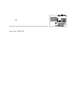
Intel Desktop Board D845PESV Product Guide Back Panel Connectors Figure 14 shows the back panel connectors. A E G L C K BD F HIJ Item A B C located on the back panel, is designed to power either headphones or amplified speakers only. Poor audio quality may occur if passive (non-amplified) - Intel D845PESV | Product Guide - Page 67
Audio Connectors Figure 15 shows the location of the audio connectors. A 1 3 2 4 B 5 6 7 9 10 C 1 1 Technical Reference Item Description Color A Front panel audio B Auxiliary line in (ATAPI) C CD-ROM (ATAPI) Black Light grey Black Figure 15. Audio Connectors OM14733 67 - Intel D845PESV | Product Guide - Page 68
Intel Desktop Board D845PESV Product Guide Add-In Card and Peripheral Interface Connectors Figure 16 shows the add-in card and 2 (SMBus routed) Item F G H I J Description PCI bus connector 1 AGP Floppy drive Primary IDE Secondary IDE Figure 16. Add-in Card and Peripheral Interface Connectors 68 - Intel D845PESV | Product Guide - Page 69
KB 1 KB 127 KB 512 KB Description Extended Memory Runtime BIOS Reserved Available high DOS memory (open to the PCI bus) Video memory and BIOS Extended BIOS data (movable by memory manager software) Extended conventional memory Conventional memory DMA Channels Table 33. DMA Channels DMA Channel - Intel D845PESV | Product Guide - Page 70
D845PESV Product Guide Interrupts Table 34. Interrupts IRQ System Resource NMI I/O channel check 0 Reserved, interval timer 1 Reserved, keyboard buffer full 2 Reserved, cascade interrupt from slave PIC 3 ** 4 COM1* 5 LPT2 (Plug and Play option) / ** 6 Floppy drive controller - Intel D845PESV | Product Guide - Page 71
Board D845PESV reports POST errors in two ways: • By sounding a beep code • By displaying an error message on the monitor BIOS Beep Codes The BIOS beep codes are listed in Table 35. The BIOS also issues a beep code (one long tone followed by two short tones) during POST if the video configuration - Intel D845PESV | Product Guide - Page 72
Intel Desktop Board D845PESV Product Guide BIOS Error Messages When a recoverable error occurs during the POST, the BIOS displays an error message describing the problem. Table 36. BIOS Error Messages Error Message Explanation GA20 Error An error occurred with Gate-A20 when switching to - Intel D845PESV | Product Guide - Page 73
followed by an address. A parity error occurred in onboard memory. This error is followed by an address. A parity error occurred in onboard memory at an unknown address. NVRAM, CMOS, and passwords have been cleared. The system should be powered down and the jumper removed. CMOS is ignored and NVRAM - Intel D845PESV | Product Guide - Page 74
Intel Desktop Board D845PESV Product Guide 74 - Intel D845PESV | Product Guide - Page 75
B Regulatory Compliance This appendix contains: • Safety standards, electromagnetic compatibility (EMC) regulations, and product certification markings for Desktop Board D845PESV. • Instructions and precautions for integrators who are installing the desktop board in a chassis. Safety Regulations - Intel D845PESV | Product Guide - Page 76
D845PESV Product Guide Product Certification Markings Desktop Board D845PESV has the following product certification markings: • UL joint US/Canada Recognized Component mark: consists of small c followed by a stylized backward UR and followed by a small US. Includes adjacent UL file number for Intel - Intel D845PESV | Product Guide - Page 77
. Ensure Electromagnetic Compatibility (EMC) Compliance Before computer integration, make sure that the power supply and other modules or peripherals, as applicable, have passed Class B EMC testing and are marked accordingly. In the installation instructions for the host chassis, power supply, and - Intel D845PESV | Product Guide - Page 78
Intel Desktop Board D845PESV Product Guide Chassis and Component Certifications Ensure that the chassis and certain components; such as the power supply, peripheral drives to the manufacturer's instructions. Use Only for Intended Applications All Intel desktop processor boards are evaluated as
-
 1
1 -
 2
2 -
 3
3 -
 4
4 -
 5
5 -
 6
6 -
 7
7 -
8
-
9
-
10
-
11
-
12
-
13
-
14
-
15
-
16
-
17
-
18
-
19
-
20
-
21
-
22
-
23
-
24
-
25
-
26
-
27
-
28
-
29
-
30
-
31
-
32
-
33
-
34
-
35
-
36
-
37
-
38
-
39
-
40
-
41
-
42
-
43
-
44
-
45
-
46
-
47
-
48
-
49
-
50
-
51
-
52
-
53
-
54
-
55
-
56
-
57
-
58
-
59
-
60
-
61
-
62
-
63
-
64
-
65
-
66
-
67
-
68
-
69
-
70
-
71
-
72
-
73
-
74
-
75
-
76
-
77
-
78
 |
 |

Intel
®
Desktop Board
D845PESV Product Guide
Order Number:
A99406-002