Intel D865GRH D865GRH_TechProdSpec.
Intel D865GRH Manual
 |
View all Intel D865GRH manuals
Add to My Manuals
Save this manual to your list of manuals |
Intel D865GRH manual content summary:
- Intel D865GRH | D865GRH_TechProdSpec. - Page 1
November 2003 Order Number: C53954-001 The Intel® Desktop Board D865GRH may contain design defects or errors known as errata that may cause the product to deviate from published specifications. Current characterized errata are documented in the Intel Desktop Board D865GRH Specification Update. - Intel D865GRH | D865GRH_TechProdSpec. - Page 2
November 2003 This product specification applies to only the standard Intel® Desktop Board D865GRH with BIOS identifier BF86510A.86A. Changes to this specification will be published in the Intel Desktop Board D865GRH Specification Update before being incorporated into a revision of this document - Intel D865GRH | D865GRH_TechProdSpec. - Page 3
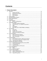
5 Description A description of the hardware used on the Desktop Board D865GRH A map of the resources of the Desktop Board The features supported by the BIOS Setup program The contents of the BIOS Setup program's menus and submenus A description of the BIOS error messages, beep codes, and POST codes - Intel D865GRH | D865GRH_TechProdSpec. - Page 4
Intel Desktop Board D865GRH Technical Product Specification WARNING Warnings indicate conditions, component, N indicates component type, xn are the relative coordinates of its location on the Desktop Board D865GRH, and X is the instance of the particular part at that general location. For example, - Intel D865GRH | D865GRH_TechProdSpec. - Page 5
Options 13 1.1.3 Board Layout 14 1.1.4 Block Diagram 15 1.2 Online Support ...16 1.3 Operating System Support 16 1.4 Design Specifications 17 1.5 Processor ...20 1.6 System Memory ...21 1.6.1 Memory Configurations 23 1.7 Intel® 865G Chipset ...28 1.7.1 Intel 865G Graphics Subsystem 29 - Intel D865GRH | D865GRH_TechProdSpec. - Page 6
Intel Desktop Board D865GRH Panel Audio Connector/Jumper Block 85 2.9.2 BIOS Board Level 96 3 Overview of BIOS Features 3.1 Introduction...97 3.2 BIOS Flash Memory Organization 97 3.3 Resource Configuration 98 3.3.1 PCI Autoconfiguration 98 3.3.2 PCI IDE Support 98 3.4 System Management BIOS - Intel D865GRH | D865GRH_TechProdSpec. - Page 7
3.5 Legacy USB Support 99 3.6 BIOS Updates ...100 3.6.1 Language Support 100 3.6.2 Custom Splash Screen 101 3.7 Recovering BIOS Data 101 3.8 Intel® Rapid BIOS Boot 103 3.9.1 Peripheral Selection and Configuration 103 3.9.2 Intel Rapid BIOS Boot 103 3.10 BIOS Security Features 104 4 BIOS - Intel D865GRH | D865GRH_TechProdSpec. - Page 8
24. Desktop Board D865GRH Dimensions 87 25. I/O Shield Dimensions 88 26. Localized High Temperature Zones 91 Tables 1. Feature Summary...12 2. Manufacturing Options 13 3. Specifications ...17 4. Supported System Bus Frequency and Memory Speed Combinations 21 5. Supported Memory Configurations - Intel D865GRH | D865GRH_TechProdSpec. - Page 9
LED 83 39. Front Panel Audio Connector/Jumper Block 86 40. BIOS Setup Configuration Jumper Settings 86 41. DC Loading Characteristics 89 42. Fan Connector Current Capability 89 43. Thermal Considerations for Components 92 44. Desktop Board D865GRH Environmental Specifications 93 45. Safety - Intel D865GRH | D865GRH_TechProdSpec. - Page 10
Intel Desktop Board D865GRH Technical Product Specification 65. Burn-In Mode Submenu 123 66. Fan Control Configuration Submenu 124 67. Hardware Monitoring Display 125 68. Security Menu ...126 69. Power Menu ...127 70. ACPI Submenu...127 71. Boot Menu ...128 72. Boot Device Priority Submenu 129 - Intel D865GRH | D865GRH_TechProdSpec. - Page 11
Chapter Contains 1.1 Overview ...12 1.2 Online Support ...16 1.3 Operating System Support 16 1.4 Design Specifications 17 1.5 Processor ...20 1.6 System Memory ...21 1.7 Intel® 865G Chipset ...28 1.8 I/O Controller ...40 1.9 Audio Subsystem...42 1.10 LAN Subsystem...45 1.11 Hardware Management - Intel D865GRH | D865GRH_TechProdSpec. - Page 12
Overview 1.1.1 Feature Summary Table 1 summarizes the major features of the Intel® Desktop Board D865GRH. Table 1. Feature Summary Form Factor Processor Memory Chipset Video Audio I/O Control USB Peripheral Interfaces LAN Support microATX (9.60 inches by 9.60 inches [243.84 millimeters by 243 - Intel D865GRH | D865GRH_TechProdSpec. - Page 13
1.4, page 17 1.1.2 Manufacturing Options Table 2 describes the manufacturing options on the Desktop Board D865GRH. Not every manufacturing option is available in all marketing channels. Please contact your Intel representative to determine which manufacturing options are available to you. Table - Intel D865GRH | D865GRH_TechProdSpec. - Page 14
Intel Desktop Board D865GRH Technical Product Specification 1.1.3 Board Layout Figure 1 shows the location of the major components on the Desktop Board D865GRH. A B C D EF G H GG FF I EE DD J K CC L BB M AA Z Y X V T RQ W US P ON OM16498 A Audio codec B Front panel audio BIOS - Intel D865GRH | D865GRH_TechProdSpec. - Page 15
of the Desktop Board D865GRH. = connector or socket Parallel ATA IDE Connectors (2) Parallel ATA IDE Interface mPGA478 System Bus Processor Socket (400/533/800 MHz) LAN Connector Gigabit LAN PLC (Optional) CSA Interface AGP Interface Universal 0.8/ 1.5 V AGP 3.0 Connector Intel 82865G - Intel D865GRH | D865GRH_TechProdSpec. - Page 16
for the Desktop Board D865GRH Processor data sheets ICH5 addressing Custom splash screens Audio software and utilities LAN software and drivers Visit this World Wide Web site: http://www.intel.com/design/motherbd http://support.intel.com/support/motherboards/desktop http://developer.intel.com - Intel D865GRH | D865GRH_TechProdSpec. - Page 17
Product Description 1.4 Design Specifications Table 3 lists the specifications applicable to the Desktop Board D865GRH. Table 3. Specifications Reference Name AC '97 Specification Title Audio Codec '97 ACPI Advanced Configuration and Power Interface Specification AGP ASF ATA/ ATAPI-5 ATX - Intel D865GRH | D865GRH_TechProdSpec. - Page 18
Intel Desktop Board D865GRH Technical Product Specification Table 3. Specifications (continued) Reference Name DDR SDRAM EHCI EPP El Torito LPC MicroATX PCI Plug and Play Specification Title Double Data Rate (DDR) SDRAM Specification Design Specification for a 184 Pin DDR Unbuffered DIMM Intel® - Intel D865GRH | D865GRH_TechProdSpec. - Page 19
System Management BIOS TFX12V Power Supply Design Guide Universal Host Controller Interface Design Guide Universal Serial Bus Specification Version, Revision Date and Ownership Version 2.1, September 20, 1999, Intel Corporation. Version 2.0, May 2001, Intel Corporation. Version 2.3.1, March 16 - Intel D865GRH | D865GRH_TechProdSpec. - Page 20
Intel Desktop Board D865GRH Technical Product Specification 1.5 Processor ✏ NOTE Refer to Thermal Considerations (Section 2.12, page 90) for important information when using an Intel Pentium 4 processor operating above 2.80 GHz with this Intel desktop board. The board is designed to support the - Intel D865GRH | D865GRH_TechProdSpec. - Page 21
Product Description 1.6 System Memory The Desktop Board D865GRH has four DIMM sockets and supports the following memory features: • 2.5 V (only) 184-pin DDR SDRAM DIMMs with gold-plated contacts • Unbuffered, single-sided or double-sided DIMMs with the following restriction: Double-sided DIMMS - Intel D865GRH | D865GRH_TechProdSpec. - Page 22
Intel Desktop Board D865GRH Technical Product Specification Table 5 lists the supported DIMM configurations. Table 5. Supported Memory Configurations DIMM Capacity DDR SDRAM Configuration Density DDR SDRAM Organization Number of DDR Front-side/Back-side SDRAM Devices 64 MB SS 64 Mbit 8 M - Intel D865GRH | D865GRH_TechProdSpec. - Page 23
Product Description 1.6.1 Memory Configurations The Intel 82865G GMCH component provides two features for enhancing memory throughput: • Dual Channel memory interface. The board has two memory channels, each with two DIMM sockets, as shown in Figure 3 • Dynamic Addressing Mode. Dynamic mode - Intel D865GRH | D865GRH_TechProdSpec. - Page 24
Intel Desktop Board D865GRH Technical Product Specification Dual Channel Configuration with Dynamic Mode (All DIMMs matched) Example 1 Channel A - DIMM 0 Channel A - DIMM 1 Intel 82865G GMCH Channel B - DIMM 0 Channel B - DIMM 1 Example 2 Channel A - DIMM 0 Channel A - DIMM 1 Intel 82865G - Intel D865GRH | D865GRH_TechProdSpec. - Page 25
Dynamic Mode - DIMMs not matched within channel - DIMMs match Channel A to Channel B Channel A - DIMM 0 Channel B - DIMM 0 Channel A - DIMM 1 Intel 82865G GMCH Channel B - DIMM 1 OM15971 Throughput Level Highest Lowest Configuration Dual Channel with Dynamic Mode Dual Channel without Dynamic - Intel D865GRH | D865GRH_TechProdSpec. - Page 26
Intel Desktop Board D865GRH Technical Product Specification Single Channel Configuration with Dynamic Mode (Single DIMM or DIMMs matched within Channel) Example 1 Channel A - DIMM 0 Channel A - DIMM 1 Intel 82865G GMCH Channel B - DIMM 0 Channel B - DIMM 1 Example 2 Channel A - DIMM 0 Channel - Intel D865GRH | D865GRH_TechProdSpec. - Page 27
without Dynamic Mode (DIMMs not matched) Example 1 Channel A - DIMM 0 Channel A - DIMM 1 Intel 82865G GMCH Channel B - DIMM 0 Channel B - DIMM 1 Example 2 Channel A - DIMM 0 Channel A - DIMM 1 Intel 82865G GMCH Channel B - DIMM 0 Channel B - DIMM 1 OM15970 Throughput Level Highest Lowest - Intel D865GRH | D865GRH_TechProdSpec. - Page 28
Intel Desktop Board D865GRH Technical Product Specification 1.7 Intel® 865G Chipset The Intel 865G chipset consists of the following devices: • Intel 82865G Graphics and Memory Controller Hub (GMCH) with Accelerated Hub Architecture (AHA) bus • Intel 82801EB I/O Controller Hub (ICH5) with AHA bus • - Intel D865GRH | D865GRH_TechProdSpec. - Page 29
for software MPEG2 decode Two multiplexed DVO port interfaces with 165 MHz pixel clocks using an AGP Digital Display (ADD) card • Dynamic Video Memory Technology (DVMT) support up to 64 MB For information about DVMT Obtaining graphics software and utilities Refer to Section 1.7.1.3, page 35 - Intel D865GRH | D865GRH_TechProdSpec. - Page 30
Intel Desktop Board D865GRH Technical Product Specification Table 7. Direct Draw Supported Modes Resolution 320 x 200 Color Palette 256 colors Refresh colors 70 Y 64 K colors 70 3 16 M colors 70 3 Notes: Y = Supported in driver without Direct3D* and OpenGL* 3 = Direct3D and OpenGL 30 - Intel D865GRH | D865GRH_TechProdSpec. - Page 31
Table 8. Video BIOS Video Modes Supported for Analog CRTs Resolution 320 x 200 320 x 350 360 x 400 640 x 200 640 x 350 640 x 480 Color Palette 16 colors 256 colors 16 colors 16 - Intel D865GRH | D865GRH_TechProdSpec. - Page 32
1200 1856 x 1392 1920 x 1080 1920 x 1200 1920 x 1440 2048 x 1536 Intel Desktop Board D865GRH Technical Product Specification Table 9. Supported Modes for DDR400/DDR333 Dual Channel Configuration 2D = Display only 2D+0 = 2D display + full screen Resolution 8-Bit Color 60 2D+0 2D+0 2D+0 2D+0 2D - Intel D865GRH | D865GRH_TechProdSpec. - Page 33
x 1080 1920 x 1200 1920 x 1440 2048 x 1536 Product Description Table 10. Supported Modes for DDR266 Dual Channel and DDR333/DDR400 Single Channel Configurations 2D= Display only 2D+0 = 2D display + full screen 2D+D = 2D display + DVD content Resolution 8-Bit Color 60 2D+0 2D+0 2D+0 2D+0 2D - Intel D865GRH | D865GRH_TechProdSpec. - Page 34
1200 1856 x 1392 1920 x 1080 1920 x 1200 1920 x 1440 2048 x 1536 Intel Desktop Board D865GRH Technical Product Specification Table 11. Supported Modes for DDR266 Single Channel Configuration 2D= Display only 2D+0 = 2D display + full screen Resolution 8-Bit Color 60 2D+0 2D+0 2D+0 2D+0 2D+0 2D - Intel D865GRH | D865GRH_TechProdSpec. - Page 35
VGA graphics under DOS. Once loaded, the operating system and graphics drivers allocate additional system memory to the graphics buffer as needed for performing graphics functions. ✏ NOTE The use of DVMT requires operating system driver support. 1.7.1.4 Zone Rendering Technology (ZRT) The Intel - Intel D865GRH | D865GRH_TechProdSpec. - Page 36
Intel Desktop Board D865GRH Technical Product Specification 1.7.1.6 Intelligent Memory Management (IMM) Intelligent Memory Management (IMM) technology is Intel's unique UMA memory manager architecture, consisting of these key elements: • Tiled memory addressing capability • Deep display buffer - Intel D865GRH | D865GRH_TechProdSpec. - Page 37
display is not supported when one of the display devices is a TV. • Synchronous display with two digital displays is not supported. • Digital Visual Interface (DVI) support memory read and write operations that hide memory the AGP connector on the D865GRH board Obtaining the Accelerated Graphics - Intel D865GRH | D865GRH_TechProdSpec. - Page 38
-speed devices. • Native USB 2.0 support has been tested with drivers for Windows 2000 (with Service Pack 3) and Windows XP (with Service Pack 1) and is not currently supported by any other operating system. Check Intel's Desktop Board website for possible driver updates for other operating systems - Intel D865GRH | D865GRH_TechProdSpec. - Page 39
drive reports the transfer rate and translation mode to the BIOS. The Desktop Boards support Laser Servo (LS-120) diskette technology through the Parallel Native mode is the preferred mode for configurations using the Windows XP and Windows 2000 operating systems. ✏ NOTE Many Serial ATA drives use - Intel D865GRH | D865GRH_TechProdSpec. - Page 40
Intel Desktop Board D865GRH board The signal names of the SCSI hard drive activity LED connector Refer to Figure 19, page 79 Table 33, page 80 1.7.5 Real-Time Clock, CMOS SRAM, and Battery A coin-cell battery (CR2032) powers the real-time clock and CMOS memory into CMOS RAM at power support The BIOS - Intel D865GRH | D865GRH_TechProdSpec. - Page 41
111 1.8.3 Diskette Drive Controller The I/O controller supports one diskette drive. Use the BIOS Setup program to configure the diskette drive interface. For information about The location of the diskette drive connector on the D865GRH board The supported diskette drive capacities and sizes Refer - Intel D865GRH | D865GRH_TechProdSpec. - Page 42
Intel Desktop Board D865GRH Technical Product Specification 1.9 Audio Subsystem The boards provide a Flex 6 audio subsystem based on the Analog Devices AD1985 codec. The audio subsystem supports the following features: • Advanced jack sense with Auto Topology Switching that enables the audio codec - Intel D865GRH | D865GRH_TechProdSpec. - Page 43
S/PDIF decoder OM16108 Figure 10. Adapter for S/PDIF Back Panel Connector Figure 11 is a block diagram of the Flex 6 audio subsystem. 82801EB I/O Controller Hub (ICH5) AC '97 Link AD1985 Audio Codec Rear Left and Right Out Front Left and Right Out Center and LFE (Subwoofer) Out S/PDIF Line In - Intel D865GRH | D865GRH_TechProdSpec. - Page 44
Intel Desktop Board D865GRH Technical Product Specification 1.9.3 Audio Connectors 1.9.3.1 Front Panel Audio Connector A 2 x 5-pin connector provides mic in and line out signals for front panel audio connectors. For information about The location of the connector The signal names of the front - Intel D865GRH | D865GRH_TechProdSpec. - Page 45
interface • CSMA/CD protocol engine • 8-bit CSA port interface that supports the 82547EI • PCI power management Supports ACPI technology Supports LAN wake capabilities 1.10.1 Intel® 82547EI Platform LAN Connect Device Intel 82547EI provides the following functions: • Basic 10/100/1000 Ethernet - Intel D865GRH | D865GRH_TechProdSpec. - Page 46
Intel Desktop Board D865GRH Technical Product Specification 1.10.3 LAN Subsystem Software LAN software and drivers are available from Intel's World Wide Web site. For information about Obtaining LAN software and drivers Refer to Section 1.2, page 16 1.11 Hardware Management Subsystem The - Intel D865GRH | D865GRH_TechProdSpec. - Page 47
Product Description 31 A B 1 C 3 13 FE D Item A B C D E F OM16499 Description Thermal diode, located on processor die Remote ambient temperature sensor Ambient temperature sensor (internal to hardware monitoring and fan control ASIC) Processor fan Rear chassis fan Front chassis fan Figure - Intel D865GRH | D865GRH_TechProdSpec. - Page 48
the Desktop Board D865GRH requires an operating system that provides full ACPI support. ACPI features include: • Plug and Play (including bus and device enumeration) • Power management control of individual devices, add-in boards (some add-in boards may require an ACPI-aware driver), video displays - Intel D865GRH | D865GRH_TechProdSpec. - Page 49
low-power state. Table 14 lists the power states supported by the Desktop Board D865GRH along with the associated system power targets. See the - working S1 - Processor stopped G1 - sleeping state S3 - Suspend to RAM. Context saved to RAM. C0 - working C1 - stop grant No power D0 - working state. - Intel D865GRH | D865GRH_TechProdSpec. - Page 50
Intel Desktop Board D865GRH Technical BIOS Setup program. Setting this option to Power On will enable a wake-up event from LAN in the S5 state. ✏ NOTE The use of these wake-up events from an ACPI state requires an operating system that provides full ACPI support. In addition, software, drivers - Intel D865GRH | D865GRH_TechProdSpec. - Page 51
supported and manufacturing options. The Desktop Board D865GRH provides several power management hardware features, including: • Power connector • Fan connectors • LAN the power connector The signal names of the power connector The BIOS Setup program's Boot menu The ATX12V, SFX12V, and TFX12V - Intel D865GRH | D865GRH_TechProdSpec. - Page 52
Intel Desktop Board D865GRH Technical Product Specification 1.12.2.2 Fan Connectors Table 16 Magic Packet* frame, the LAN subsystem asserts a wake-up signal that powers up the computer. Depending on the LAN implementation, the Desktop Board D865GRH supports LAN wake capabilities with ACPI in - Intel D865GRH | D865GRH_TechProdSpec. - Page 53
supply. Instantly Available PC technology enables the Desktop Board D865GRH to enter the ACPI S3 (Suspend-to-RAM) sleep-state. While in the S3 can wake the computer from the S3 state. The Desktop Board D865GRH supports the PCI Bus Power Management Interface Specification. For information on the - Intel D865GRH | D865GRH_TechProdSpec. - Page 54
Intel Desktop Board D865GRH Technical Product Specification 1.12.2.5 +5 V Standby Power Indicator LED The +5 the power cord before installing or removing any devices connected to the board. Failure to do so could damage the board and any attached devices. CR7J1 OM16500 Figure 14. Location of the - Intel D865GRH | D865GRH_TechProdSpec. - Page 55
states. ✏ NOTE Wake from USB requires the use of a USB peripheral that supports Wake from USB. 1.12.2.8 Wake from PS/2 Devices PS/2 device activity wakes from an ACPI S1 or S3 state. 1.12.2.9 PME# Signal Wake-up Support When the PME# signal on the PCI bus is asserted, the computer wakes from - Intel D865GRH | D865GRH_TechProdSpec. - Page 56
Intel Desktop Board D865GRH • Microsoft Windows 2000 Professional (SP4) or Microsoft Windows XP Intel Express Installer CD) 1.13.2 Warning of Potential Data Loss CAUTION Failure to follow the instructions below may cause you to loose data. Read and follow these instructions motherboard a BIOS switch) - Intel D865GRH | D865GRH_TechProdSpec. - Page 57
Product Description procedures may allow the migratable keys to be recovered and may restore access to encrypted data. Read the Security Precautions for Emergency Recovery File Back Up Procedures. • TPM Keys are Hierarchical: All TPM keys have a place within a hierarchy. Within this hierarchy, keys - Intel D865GRH | D865GRH_TechProdSpec. - Page 58
Intel Desktop Board D865GRH Technical Product Specification 1.13.3.1 Password Procedures The Infineon Security Platform off-site storage) and kept available for future use. These documents should be updated after any password changes. 1.13.3.2 Emergency Recovery File Back Up Procedures After - Intel D865GRH | D865GRH_TechProdSpec. - Page 59
See the detailed instructions in Enabling the displaying the splash screen (or POST screen), press the key to enter the BIOS display should show: Trusted Platform Module [Enabled]). 4. Press the key, select Ok and press . 5. The system should reboot and start Microsoft Windows - Intel D865GRH | D865GRH_TechProdSpec. - Page 60
Intel Desktop Board D865GRH Technical Product Specification 1.13.6 Assuming Trusted Platform Module Ownership Once the TPM has been enabled, ownership must safe deposit box, off-site storage, etc.) in case they are needed in the future. These documents should be updated after any password changes. 60 - Intel D865GRH | D865GRH_TechProdSpec. - Page 61
original operating system installation, or a restored image of the hard drive 1. Replace the desktop board with the same model as the failed board. 2. Enable TPM in the BIOS of the replacement motherboard. 3. Start the original operating system or restore the original hard drive image. 4. Start - Intel D865GRH | D865GRH_TechProdSpec. - Page 62
Intel Desktop Board D865GRH to encrypted data. Review the Recovery Procedures for detailed instructions. The TPM may be cleared to transfer ownership of the BIOS Setup Configuration jumper (J9J4) on the board to pins 1-2. When cleared, the TPM module is disabled by default. 1.13.9 Software Support - Intel D865GRH | D865GRH_TechProdSpec. - Page 63
by text found with their respective section headings. 2.2 Memory Resources 2.2.1 Addressable Memory The board utilizes 4 GB of addressable system memory. Typically the address space that is allocated for PCI add-in cards, AGP aperture, BIOS (firmware hub), and chipset overhead resides above the top - Intel D865GRH | D865GRH_TechProdSpec. - Page 64
Intel Desktop Board D865GRH Technical Product Specification memory that can be accessed. In addition, the Video Frame Buffer setting in the BIOS Setup program will further reduce the amount of memory available to the operating system. Figure 15 shows a schematic of the system memory map. All - Intel D865GRH | D865GRH_TechProdSpec. - Page 65
(open to the PCI bus). Dependent on video adapter used. Video memory and BIOS Extended BIOS data (movable by memory manager software) Extended conventional memory Conventional memory 2.3 DMA Channels Table 18. DMA Channels DMA Channel Number 0 1 2 3 4 5 6 7 Data Width 8 or 16 bits 8 or 16 bits - Intel D865GRH | D865GRH_TechProdSpec. - Page 66
Intel Desktop Board D865GRH Technical Product Specification 2.4 Fixed I/O Map Table 19. I/O Map Address (hex) Size Description 0000 - 00FF 256 bytes Used by the Desktop Board D865GRH. Refer to the ICH5 data sheet for dynamic addressing information. 0170 - 0177 8 bytes Secondary Parallel - Intel D865GRH | D865GRH_TechProdSpec. - Page 67
Memory controller of Intel 82865G component 00 01 00 Host to AGP bridge (virtual PCI-to-PCI) 00 02 00 Intel SMBus controller 00 1F 05 AC '97 audio controller 00 1F 06 AC '97 controller AGP add-in card (if present) Intel 82547EI Gigabit LAN PLC PCI bus connector 1 PCI bus connector - Intel D865GRH | D865GRH_TechProdSpec. - Page 68
Intel Desktop Board D865GRH Technical Product Specification 2.6 Interrupts The interrupts can be routed through either the Programmable Interrupt Controller (PIC) or the Advanced Programmable Interrupt Controller (APIC) portion of the ICH5 component. The PIC is supported in Windows 98 SE and - Intel D865GRH | D865GRH_TechProdSpec. - Page 69
PIRQ signals. Some PCI interrupt sources are electrically tied together on the Desktop Board D865GRH and therefore share the same interrupt. Table 23 shows an example of which is already connected to the ICH5 audio controller. The add-in card in PCI bus connector 3 now shares an interrupt - Intel D865GRH | D865GRH_TechProdSpec. - Page 70
Intel Desktop Board D865GRH Technical Product Specification Table 23. PCI Interrupt Routing Map PCI Interrupt Source PIRQA AGP connector INTA ICH5 USB UHCI controller 1 INTA SMBus controller ICH5 USB UHCI controller 2 AC '97 ICH5 Audio ICH5 LAN ICH5 USB UHCI controller 3 ICH5 USB UHCI - Intel D865GRH | D865GRH_TechProdSpec. - Page 71
VGA port LAN Audio (line out, line in, and mic in) • Internal I/O connectors (see page 73) Audio (auxiliary line input, ATAPI CD-ROM, and front panel audio) Fans [three] Power Add-in boards power LED) ✏ NOTE When installing the D865GRH board in a microATX chassis, make sure that - Intel D865GRH | D865GRH_TechProdSpec. - Page 72
Intel Desktop Board D865GRH Technical Product Specification 2.8.1 Back Panel PS/2 keyboard port C USB ports D Serial port A E Parallel port F VGA port G LAN H USB ports I Audio line in J Mic in K Audio front left and right out Color Green Purple Black Teal Burgundy Dark blue Black Black - Intel D865GRH | D865GRH_TechProdSpec. - Page 73
Front panel audio • Power and hardware control (see page 76) Fans [3] ATX12V power Main power Chassis intrusion • Add-in boards and peripheral interfaces PCI add-in cards with SMBus support can access sensor data and other information residing on the board. ✏ NOTE The SMBus routing to - Intel D865GRH | D865GRH_TechProdSpec. - Page 74
Intel Desktop Board D865GRH Technical Product Specification ✏ NOTE This document references back-panel slot numbering with respect to processor location on the board 79) illustrates the board's PCI slot numbering. 2.8.2.2 Audio Connectors Figure 17 shows the location of the audio connectors. A B - Intel D865GRH | D865GRH_TechProdSpec. - Page 75
line in Table 25. ATAPI CD-ROM Connector Pin Signal Name 1 Left audio input from CD-ROM 2 CD audio differential ground 3 CD audio differential ground 4 Right audio input from CD-ROM Table 26. Front Panel Audio Connector Pin Signal Name Pin 1 Mono Mic in (Stereo Mic 1) 2 3 Mono - Intel D865GRH | D865GRH_TechProdSpec. - Page 76
Intel Desktop Board D865GRH Technical Product Specification 2.8.2.3 Power and Hardware Control Connectors Figure 18 shows the location of the power and hardware control connectors. A B 1 3 12 34 1 3 113 20 11 1 - Intel D865GRH | D865GRH_TechProdSpec. - Page 77
Technical Reference # INTEGRATOR'S NOTES • Use only ATX12V-, SFX12V-, or TFX12V-compliant power supplies with the Desktop Board D865GRH. ATX12V, SFX12V, and TFX12V power supplies have an additional power lead that provides required supplemental power for the processor. Always connect the 20-pin and - Intel D865GRH | D865GRH_TechProdSpec. - Page 78
Intel Desktop Board D865GRH Technical Product Specification Table 31. Front Chassis Fan Connector Pin Signal Name 1 Control 2 +12 V 3 Tach Table 32. Chassis Intrusion Connector Pin Signal Name 1 Intruder 2 Ground 78 - Intel D865GRH | D865GRH_TechProdSpec. - Page 79
the Desktop Board D865GRH. Note the following considerations for the PCI bus connectors: • All of the PCI bus connectors are bus master capable. • SMBus signals are routed to PCI bus connector 2. This enables PCI bus add-in boards with SMBus support to access sensor data on the Desktop Board. The - Intel D865GRH | D865GRH_TechProdSpec. - Page 80
Intel Desktop Board D865GRH Technical Product Specification # INTEGRATOR'S NOTE The AGP connector is keyed for Universal 0.8 V AGP 3.0 cards or 1.5 V AGP 2.0 cards only. Do not attempt to install a legacy 3.3 V AGP - Intel D865GRH | D865GRH_TechProdSpec. - Page 81
2.8.3 External I/O Connectors Figure 20 shows the locations of the external I/O connectors. Technical Reference 2 D 1 7 10 C 12 7 10 1 2 B 8 9 13 Item A B C D A OM16504 Description Auxiliary front panel power/sleep/message-waiting LED Front panel Front panel USB Front panel USB - Intel D865GRH | D865GRH_TechProdSpec. - Page 82
Intel Desktop Board D865GRH Technical Product Specification 2.8.3.1 Auxiliary Front Panel Power/Sleep/Message-Waiting LED Connector Pins 1 and 3 of this connector duplicate the signals on pins 2 and 4 of the - Intel D865GRH | D865GRH_TechProdSpec. - Page 83
Pins 5 and 7 can be connected to a momentary single pole, single throw (SPST) type switch that is normally open. When the switch is closed, the board resets and runs the POST. 2.8.3.2.3 Power/Sleep/Message Waiting LED Connector Pins 2 and 4 can be connected to a one- or two-color LED. Table 37 - Intel D865GRH | D865GRH_TechProdSpec. - Page 84
Intel Desktop Board D865GRH Technical Product Specification 2.8.3.3 Front Panel USB Connectors Figure 22 is a connection diagram for the front panel USB connectors. # INTEGRATOR'S NOTES • The +5 V DC power on the - Intel D865GRH | D865GRH_TechProdSpec. - Page 85
before changing a jumper setting. Otherwise, the Desktop Board could be damaged. Figure 23 shows the location of the jumper blocks. A 12 9 10 J9A2 B 1 3 J9J4 Item A B OM16505 Description Front panel audio connector/jumper block BIOS Setup configuration jumper block Reference Designator J9A2 - Intel D865GRH | D865GRH_TechProdSpec. - Page 86
Intel Desktop Board D865GRH Technical Product Specification Table 39 describes the two configurations of this connector/jumper block. CAUTION Do not place jumpers on this block in any configuration other than the one described in Table 39. Other jumper configurations are not supported and could - Intel D865GRH | D865GRH_TechProdSpec. - Page 87
designed to fit into either a microATX or an ATX-form-factor chassis. Figure 24 illustrates the mechanical form factor for the Desktop Board D865GRH. Dimensions are given in inches [millimeters]. The outer dimensions are 9.60 inches by 9.60 inches [243.84 millimeters by 243.84 millimeters]. Location - Intel D865GRH | D865GRH_TechProdSpec. - Page 88
Intel Desktop Board D865GRH Technical Product Specification 2.10.1 I/O Shield The back panel I/O shield for the Desktop Board D865GRH must meet specific dimension and material requirements. Systems based on these Desktop Boards need the back panel I/O shield to pass certification testing. Figure 25 - Intel D865GRH | D865GRH_TechProdSpec. - Page 89
0.03 A 13.00 A 0.10 A +5 VSB 0.60 A 1.38 A 2.11.2 Add-in Board Considerations The boards are designed to provide 2 A (average) of +5 V current for each add-in board. The total +5 V current draw for a fully loaded Desktop Board D865GRH (all three expansion slots and the AGP slot filled) must not - Intel D865GRH | D865GRH_TechProdSpec. - Page 90
Intel Desktop Board D865GRH Technical Product Specification 2.11.4 Power Supply Considerations CAUTION power supply. The total amount of standby current required depends on the wake devices supported and manufacturing options. System integrators should refer to the power usage values listed in - Intel D865GRH | D865GRH_TechProdSpec. - Page 91
CAUTION Ensure that the ambient temperature does not exceed the Desktop Board's maximum operating temperature. Failure to do so could cause . Item A B C D Description Processor voltage regulator area Processor Intel 82865G GMCH Intel 82801EB ICH5 Figure 26. Localized High Temperature Zones 91 - Intel D865GRH | D865GRH_TechProdSpec. - Page 92
airflow to cool the Desktop Board D865GRH. Table 43. Thermal Considerations for Components Component Intel Pentium 4 processor Intel 82865G GMCH Intel 82801EB ICH5 Maximum Case Temperature For processor case temperature, see processor datasheets and processor specification updates 99 oC (under - Intel D865GRH | D865GRH_TechProdSpec. - Page 93
. Desktop Board D865GRH Environmental Specifications Parameter Specification Temperature Non-Operating -40 °C to +70 °C Operating 0 °C to +55 °C Shock Unpackaged 50 g trapezoidal waveform Velocity change of 170 inches/second Packaged Half sine 2 millisecond Product Weight (pounds) Free - Intel D865GRH | D865GRH_TechProdSpec. - Page 94
Intel Desktop Board D865GRH Technical Product Specification 2.15 Regulatory Compliance This section describes the Desktop Boards' compliance with U.S. and international safety and electromagnetic compatibility (EMC) regulations. 2.15.1 Safety Regulations Table 45 lists the safety regulations the - Intel D865GRH | D865GRH_TechProdSpec. - Page 95
energy and, if not installed and used in accordance with the instructions, may cause harmful interference to radio communications. However, there of Conformity Statement We, Intel Corporation, declare under our sole responsibility that the product: Intel® Desktop Board D865GRH is in conformity with - Intel D865GRH | D865GRH_TechProdSpec. - Page 96
joint US/Canada Recognized Component mark. Includes adjacent UL file number for Intel Desktop Boards: E210882 (component side). FCC Declaration of Conformity logo mark for Class B equipment; includes Intel name and D865GRH model designation (component side). Marking CE mark. Declares compliance to - Intel D865GRH | D865GRH_TechProdSpec. - Page 97
3.1 Introduction The Desktop Board D865GRH uses an Intel/AMI BIOS that is stored in the Firmware Hub (FWH) and can be updated using a disk-based program. The FWH contains the BIOS Setup program, POST, the PCI auto-configuration utility, and Plug and Play support. The BIOS displays a message during - Intel D865GRH | D865GRH_TechProdSpec. - Page 98
Intel Desktop Board D865GRH Technical Product Specification 3.3 Resource Configuration 3.3.1 PCI Autoconfiguration The BIOS for the supported version of ATAPI). The BIOS determines the the auto-configuration options by specifying manual configuration in the BIOS Setup program. To use ATA-66 - Intel D865GRH | D865GRH_TechProdSpec. - Page 99
the SMBIOS information. The BIOS supports an SMBIOS table interface for such operating systems. Using this support, an SMBIOS service-level application running on a non-Plug and Play operating system can obtain the SMBIOS information. For information about The Desktop Boards' compliance level with - Intel D865GRH | D865GRH_TechProdSpec. - Page 100
Intel Desktop Board D865GRH Technical Product Specification To install an operating system that supports USB, verify that Legacy USB support in the BIOS Setup program is set to Enabled and follow the operating system's installation instructions. ✏ NOTE Legacy USB support is for keyboards, mice, and - Intel D865GRH | D865GRH_TechProdSpec. - Page 101
recovery diskette, a bootable diskette must be created and the BIOS update files copied to it. BIOS upgrades and the Intel Flash Memory Update Utility are available from Intel Customer Support through the Intel World Wide Web site. ✏ NOTE Even if the computer is configured to boot from an LS-120 - Intel D865GRH | D865GRH_TechProdSpec. - Page 102
Intel Desktop Board D865GRH Technical Product Specification 3.8 Boot Options In the BIOS supported in compliance to the El Torito bootable CD-ROM format specification. Under the Boot menu in the BIOS onboard LAN or displayed. This menu displays the list of available boot devices (as set in the BIOS - Intel D865GRH | D865GRH_TechProdSpec. - Page 103
time. • Eliminate unnecessary add-in adapter features, such as logo displays, screen repaints, or mode changes in POST. These features may Intel Rapid BIOS Boot. This feature bypasses memory count and the search for a diskette drive. In the Peripheral Configuration submenu, disable the LAN device - Intel D865GRH | D865GRH_TechProdSpec. - Page 104
Intel Desktop Board D865GRH Technical Product Specification 3.10 BIOS Security Features The BIOS includes security features that restrict access to the BIOS Setup program and who can boot the computer. A supervisor password and a user password can be set for the BIOS will be displayed before the - Intel D865GRH | D865GRH_TechProdSpec. - Page 105
Exit Saves or discards changes to Setup program options ✏ NOTE In this chapter, all examples of the BIOS Setup program menu bar include the maintenance menu; however, the maintenance menu is displayed only when the Desktop Board is in configure mode. Section 2.9.2 on page 86 tells how to put the - Intel D865GRH | D865GRH_TechProdSpec. - Page 106
Intel Desktop Board D865GRH Technical Product Specification Table 51 lists the function keys available for menu screens. Table 51. BIOS Setup Program Function Keys BIOS Microcode Update Revision No options No options Displays CPU's Stepping Signature. Displays CPU's Microcode Update Revision. - Intel D865GRH | D865GRH_TechProdSpec. - Page 107
present only when a processor that supports Hyper-Threading Technology is installed. Displays processor speed. Displays the system bus speed. Displays the system memory speed. Displays the size of second-level cache. Displays the total amount of RAM. Displays the memory mode (Dual Channel or Single - Intel D865GRH | D865GRH_TechProdSpec. - Page 108
Intel Desktop Board D865GRH display submenu Boot Configuration Select to display submenu Peripheral Configuration Select to display submenu Drive Configuration Select to display submenu Floppy Configuration Select to display features. Configures USB support. Configures advanced chipset - Intel D865GRH | D865GRH_TechProdSpec. - Page 109
BIOS Setup Program 4.4.1 PCI Configuration Submenu To access this submenu, select Advanced on the menu bar and then PCI Configuration. Maintenance Main Advanced Security Power PCI - Intel D865GRH | D865GRH_TechProdSpec. - Page 110
Intel Desktop Board D865GRH Technical Product Specification 4.4.2 Boot Configuration Submenu To access No (default) • Yes • Off • On (default) Description Specifies if manual configuration is desired. No lets the BIOS configure all devices. This setting is appropriate when using a Plug and Play - Intel D865GRH | D865GRH_TechProdSpec. - Page 111
BIOS Setup Program 4.4.3 Peripheral Configuration Submenu To access this submenu, select • Enabled • Auto (default) Auto assigns the first free COM port, normally COM1, the address 3F8h, and the interrupt IRQ4. An * (asterisk) displayed next to an address indicates a conflict with another device - Intel D865GRH | D865GRH_TechProdSpec. - Page 112
Intel Desktop Board D865GRH Technical Product Specification Table 57. Peripheral Configuration Submenu ( Audio • Enabled (default) Enables or disables the onboard audio subsystem. • Disabled Onboard LAN • Enabled (default) Enables or disables the onboard LAN device. • Disabled ASF Support - Intel D865GRH | D865GRH_TechProdSpec. - Page 113
BIOS Setup Program 4.4.4 Drive Configuration Submenu To access this submenu, select Advanced on the menu bar and then Drive Configuration. only when the ATA/IDE configuration option is set to Legacy. Enables/disables the use of DMA for hard drive BIOS INT13 reads and writes. continued 113 - Intel D865GRH | D865GRH_TechProdSpec. - Page 114
Intel Desktop Board D865GRH Technical Product Specification Table 58. Drive Configuration Submenu (continued Seconds • 15 Seconds • 21 Seconds • 30 Seconds Select to display sub-menu Select to display sub-menu Select to display sub-menu Description Specifies the hard disk drive pre-delay. Reports - Intel D865GRH | D865GRH_TechProdSpec. - Page 115
BIOS Setup Program 4.4.4.1 SATA/PATA Submenus To access these submenus, select Advanced on the menu bar, then Drive Configuration, and then the master or slave to - Intel D865GRH | D865GRH_TechProdSpec. - Page 116
Intel Desktop Board D865GRH Technical Product Specification Table 59. SATA/PATA Submenus -120 drive is attached to the system, a row entitled ARMD Emulation Type will be displayed in the above table. The BIOS will always recognize the drive as an ATAPI floppy drive. The ARMD Emulation Type should - Intel D865GRH | D865GRH_TechProdSpec. - Page 117
BIOS Setup Program 4.4.5 Floppy Configuration Submenu To access this menu, select Advanced on the menu bar and then Floppy Configuration. Maintenance Main Advanced Security Power PCI - Intel D865GRH | D865GRH_TechProdSpec. - Page 118
Intel Desktop Board D865GRH Technical Product Specification 4.4.6 Event Log Configuration ) • Ok (default) • Cancel Description Indicates if there is space available in the event log. Displays the event log. Clears the event log after rebooting. Enables/disables logging of DMI events. Marks all - Intel D865GRH | D865GRH_TechProdSpec. - Page 119
BIOS Setup Program 4.4.7 Video Configuration Submenu To access this menu, select Advanced on . Selects primary video adapter to be used during boot. Controls how much system RAM is reserved for use by the internal graphics device. A larger frame buffer should provide higher performance. 119 - Intel D865GRH | D865GRH_TechProdSpec. - Page 120
Intel Desktop Board D865GRH Technical Product Support • Disabled • Enabled (default) USB 2.0 Legacy Support • Full-Speed (default) • Hi-Speed Description Set to Disabled when a USB 2.0 driver is not available. Enables/disables legacy USB support. Configures the USB 2.0 Legacy support - Intel D865GRH | D865GRH_TechProdSpec. - Page 121
BIOS 32 (default) • 64 • 96 • 128 • 160 • 192 • 224 • 248 Select to display Burn-In Mode submenu • Default (default) • User Defined • Auto (default) • 266 MHz • setting of extended configuration options. Allows override of the detected memory frequency. NOTE: If SDRAM Frequency is changed, you must - Intel D865GRH | D865GRH_TechProdSpec. - Page 122
Intel Desktop Board D865GRH Technical memory detected. Manual - Aggressive = Selects most aggressive user-defined timings. Manual - User Defined = Allows manual 1. This feature is displayed only if Extended Configuration is set to User Defined. 2. This option is displayed only if the installed - Intel D865GRH | D865GRH_TechProdSpec. - Page 123
BIOS Setup Continue Graphics Core Frequency • 266 MHz (default) • 333 MHz (Not supported) Description Enables or disables setting of burn-in mode options. Burn-in covered by Intel component warranties. If any problems occur during operation at non-default settings, return the board to default - Intel D865GRH | D865GRH_TechProdSpec. - Page 124
Intel Desktop Board D865GRH Technical Product Specification 4.4.10 Fan Control Configuration Submenu To options will not take effect until power has been completely removed from the system. After saving the BIOS settings and turning off the system, unplug the power cord from the system and wait at - Intel D865GRH | D865GRH_TechProdSpec. - Page 125
BIOS Setup Program 4.4.11 Hardware Monitoring To access this screen, select Advanced on the menu Boot Exit Table 67 represents an example of the hardware monitoring display. Table 67. Hardware Monitoring Display Feature Processor Zone Temperature System Zone 1 Temperature System Zone 2 - Intel D865GRH | D865GRH_TechProdSpec. - Page 126
Intel Desktop Board D865GRH cleared and the event log is updated. Log, notify til cleared = Halts system during POST. User must enter BIOS setup Security Menu and select " and 0-9. This feature is displayed only if a supervisor password has been set. This feature is displayed only if a user password - Intel D865GRH | D865GRH_TechProdSpec. - Page 127
BIOS Menu Feature ACPI After Power Failure Wake on PCI PME Options Select to display submenu • Stay Off • Last State (default) • Power On • LAN from S5 • Stay Off (default) • Power On Description S1 is the safest mode but consumes more power. S3 consumes less power, but some drivers may not support - Intel D865GRH | D865GRH_TechProdSpec. - Page 128
Intel Desktop Board D865GRH Technical Product Specification 4.7 Boot Menu To access this menu, select Boot from the menu bar at the top of the screen. Maintenance Main Advanced Security - Intel D865GRH | D865GRH_TechProdSpec. - Page 129
BIOS Setup Program 4.7.1 Boot Device Priority Submenu To access this menu, select Device 3rd Boot Device 4th Boot Device Options • Removable Dev. • Hard Drive • ATAPI CD-ROM • Intel® Boot Agent (Note) • Disabled Description Specifies the boot sequence according to the device type. The computer - Intel D865GRH | D865GRH_TechProdSpec. - Page 130
Intel Desktop Board D865GRH Technical Product Specification 4.7.2 Hard Disk Drives Submenu To device of this type is installed. This list will display up to twelve hard disk drives, the maximum number of hard disk drives supported by the BIOS. 4.7.3 Removable Devices Submenu To access this menu, - Intel D865GRH | D865GRH_TechProdSpec. - Page 131
installed. This list will display up to four ATAPI CD-ROM drives, the maximum number of ATAPI CD-ROM drives supported by the BIOS. 4.8 Exit Menu To BIOS reads the Setup values from flash memory. If this memory is corrupted, the BIOS reads the custom defaults. If no custom defaults are set, the BIOS - Intel D865GRH | D865GRH_TechProdSpec. - Page 132
Intel Desktop Board D865GRH Technical Product Specification 132 - Intel D865GRH | D865GRH_TechProdSpec. - Page 133
5.5 BIOS Beep Codes ...140 5.1 BIOS Error Messages Table 77 lists the error messages and provides a brief description of each. Table 77. BIOS Error Slave Drive - ATAPI Incompatible A: Drive Error Cache Memory Bad CMOS Battery Low CMOS Display Type Wrong CMOS Checksum Bad CMOS Settings Wrong CMOS - Intel D865GRH | D865GRH_TechProdSpec. - Page 134
Intel Desktop Board D865GRH Technical Product Specification Table 77. BIOS Error Messages (continued) Error Message Checking NVRAM..... Update OK! Updated Failed Keyboard Error KB/Interface Error Memory Size Decreased Memory Size Increased Memory Size Changed No Boot Device Available Explanation - Intel D865GRH | D865GRH_TechProdSpec. - Page 135
and display the contents on a medium such as a seven-segment display. ✏ start memory refresh, and do memory sizing. Verify base memory. BIOS. Find Main BIOS module in ROM image. Uncompress the main BIOS module. Copy main BIOS image to F000 shadow RAM and give control to main BIOS in F000 shadow RAM - Intel D865GRH | D865GRH_TechProdSpec. - Page 136
Intel Desktop Board D865GRH Technical Product Specification Table 80. Runtime Code Uncompressed in F000 Shadow RAM Code 03 05 06 07 08 0B 0C 0E 0F 10 11 12 13 14 19 Description of POST Operation NMI is Disabled. To check soft reset/power-on. BIOS stack set. Going to disable cache if any. POST - Intel D865GRH | D865GRH_TechProdSpec. - Page 137
NOT SOFT RESET) About to display the first 64k memory size. 4F Memory size display started. This will be updated during memory test. Going for sequential and random memory test. 50 Memory testing/initialization below 1M complete. Going to adjust displayed memory size for relocation/shadow. 51 - Intel D865GRH | D865GRH_TechProdSpec. - Page 138
Intel Desktop Board D865GRH Technical Product Specification Table 80. Runtime Code Uncompressed in F000 Shadow RAM (continued) POST Operation Lock-key checking over. To check for memory size mismatch with CMOS. Memory size check done. To display soft error and check for password or bypass setup. - Intel D865GRH | D865GRH_TechProdSpec. - Page 139
Uncompressed in F000 Shadow RAM (continued) Code AE and general devices) to start if present. 39 Display different buses initialization error messages. 95 Init of different , the low byte of the checkpoint is the system BIOS checkpoint from which the control is passed to the different - Intel D865GRH | D865GRH_TechProdSpec. - Page 140
Intel Desktop Board D865GRH Technical Product Specification Table 83 describes the lower Desktop Board D865GRH Refer to Figure 1, on page 14 5.5 BIOS Beep Codes Whenever a recoverable error occurs during POST, the BIOS displays an error message describing the problem (see Table 84). The BIOS - Intel D865GRH | D865GRH_TechProdSpec. - Page 141
2 Parity cannot be reset 3 First 64 KB memory failure 4 Timer not operational 5 Not used 6 8042 GateA20 cannot be toggled 7 Exception interrupt error 8 Display memory R/W error 9 Not used 10 CMOS Shutdown register test error 11 Invalid BIOS (e.g. POST module not found, etc.) 141 - Intel D865GRH | D865GRH_TechProdSpec. - Page 142
Intel Desktop Board D865GRH Technical Product Specification 142
-
 1
1 -
 2
2 -
 3
3 -
 4
4 -
 5
5 -
 6
6 -
 7
7 -
8
-
9
-
10
-
11
-
12
-
13
-
14
-
15
-
16
-
17
-
18
-
19
-
20
-
21
-
22
-
23
-
24
-
25
-
26
-
27
-
28
-
29
-
30
-
31
-
32
-
33
-
34
-
35
-
36
-
37
-
38
-
39
-
40
-
41
-
42
-
43
-
44
-
45
-
46
-
47
-
48
-
49
-
50
-
51
-
52
-
53
-
54
-
55
-
56
-
57
-
58
-
59
-
60
-
61
-
62
-
63
-
64
-
65
-
66
-
67
-
68
-
69
-
70
-
71
-
72
-
73
-
74
-
75
-
76
-
77
-
78
-
79
-
80
-
81
-
82
-
83
-
84
-
85
-
86
-
87
-
88
-
89
-
90
-
91
-
92
-
93
-
94
-
95
-
96
-
97
-
98
-
99
-
100
-
101
-
102
-
103
-
104
-
105
-
106
-
107
-
108
-
109
-
110
-
111
-
112
-
113
-
114
-
115
-
116
-
117
-
118
-
119
-
120
-
121
-
122
-
123
-
124
-
125
-
126
-
127
-
128
-
129
-
130
-
131
-
132
-
133
-
134
-
135
-
136
-
137
-
138
-
139
-
140
-
141
-
142
 |
 |

November 2003
Order Number:
C53954-001
The Intel
®
Desktop Board D865GRH may contain design defects or errors known as errata that may cause the product to deviate from published specifications.
Current
characterized errata are documented in the Intel Desktop Board D865GRH Specification Update.
Intel
®
Desktop Board
D865GRH
Technical Product Specification