Intel D915GAG User Manual
Intel D915GAG Manual
 |
View all Intel D915GAG manuals
Add to My Manuals
Save this manual to your list of manuals |
Intel D915GAG manual content summary:
- Intel D915GAG | User Manual - Page 1
Intel® Desktop Board D915GEV/D915GUX/ D915GAV/D915GAG Product Guide Order Number: C64136-002 - Intel D915GAG | User Manual - Page 2
Intel® Desktop Board D915GEV/D915GUX/ D915GAV/D915GAG Product Guide. Second release of Intel® Desktop Board D915GEV/D915GUX/ D915GAV/D915GAG Product Guide . Intel may make changes to specifications and product descriptions at any time, without notice. Desktop Board D915GEV/D915GUX/D915GAV/D915GAG may - Intel D915GAG | User Manual - Page 3
Preface This Product Guide gives information about board layout, component installation, BIOS update, and regulatory requirements for Intel® Desktop Board D915GEV/D915GUX/D915GAV/D915GAG. Intended Audience The Product Guide is intended for technically qualified personnel. It is not intended for - Intel D915GAG | User Manual - Page 4
Intel Desktop Board D915GEV/D915GUX/D915GAV/D915GAG Product Guide Terminology The table below gives descriptions to some common terms used in the product guide. Term Description GB Gigabyte (1,073,741,824 bytes) GHz Gigahertz (one billion hertz) KB Kilobyte (1024 bytes) MB Megabyte (1, - Intel D915GAG | User Manual - Page 5
Systems 11 Desktop Board Components 12 Processor ...16 Main Memory ...17 Intel® 915G Express Chipset 18 Graphics Subsystem ...19 Audio Subsystem ...19 Input/Output (I/O) Controller 20 LAN Subsystem (Optional)...20 LAN Subsystem Software 20 RJ-45 LAN Connector LEDs 20 Hi-Speed USB 2.0 Support - Intel D915GAG | User Manual - Page 6
Intel Desktop Board D915GEV/D915GUX/D915GAV/D915GAG Product Guide Installing and Removing the Desktop Board 31 Installing and Removing a Processor 32 Installing a Processor 32 Installing the Processor Fan Heat Sink 34 Connecting the Processor Fan Heat Sink Cable 35 Removing the Processor 35 - Intel D915GAG | User Manual - Page 7
and D915GEV Components 12 2. Intel Desktop Boards D915GUX and D915GAG Components 14 3. Back Panel LAN Connector LED Locations 20 4. Location of Standby Power Indicator 25 5. Installing the I/O Shield 30 6. Desktop Boards D915GEV and D915GAV Mounting Screw Hole Locations 31 7. Lift Socket Lever - Intel D915GAG | User Manual - Page 8
15 5. Desktop Board D915GAV/D915GAG Memory Configurations 17 6. Desktop Board D915GEV/D915GUX Memory Configurations 18 7. RJ-45 10/100 Ethernet LAN Connector LEDs 21 8. RJ-45 10/100/1000 Gigabit Ethernet LAN Connector LEDs 21 9. Front Panel Audio Header Signal Names 45 10. USB 2.0 Header - Intel D915GAG | User Manual - Page 9
Support for an Intel® Pentium® 4 processor in the LGA775 package Desktop Boards D915GAV and D915GAG: • Four 184-pin, 2.5 V SDRAM Dual Inline Memory Module (DIMM) sockets • 400/333 MHz single or dual channel DDR SDRAM interface • Designed to support up to 4 GB of system memory Desktop Boards D915GEV - Intel D915GAG | User Manual - Page 10
(Optional) Trusted Platform Module (Optional) Related Links: For more information about Intel Desktop Board D915GEV/D915GUX/D915GAV/D915GAG, including the Technical Product Specification (TPS), BIOS updates, and device drivers, go to: http://support.intel.com/support/motherboards/desktop/ 10 - Intel D915GAG | User Manual - Page 11
options for Desktop Board D915GEV/D915GUX/ D915GAV/D915GAG. Table 2. Manufacturing Options Option LAN Gigabit LAN Gigabit LAN and TPM Description Intel® 82562EZ 10/100 Mbit/sec Platform LAN Connect (PLC) device with RJ-45 connector • Marvell* 88E8050 PCI Express Gigabit Ethernet Controller (10 - Intel D915GAG | User Manual - Page 12
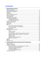
Intel Desktop Board D915GEV/D915GUX/D915GAV/D915GAG Product Guide Desktop Board Components Figure 1 shows the approximate location of the major components on desktop boards D915GAV and D915GEV. Line In RJ45 A BC W V D U E T F G Channel A DIMM 0 DIMM 1 S Channel B DIMM 0 DIMM 1 R Q - Intel D915GAG | User Manual - Page 13
R S T U V W Desktop Boards D915GAV and D915GEV Components Description Front panel audio header PCI Express x16 connector Rear chassis fan header 1 (fan speed control) Alternate power connector (1x4) 12 V processor core voltage connector (2x2) Processor socket Processor fan header (4-pin, fan speed - Intel D915GAG | User Manual - Page 14
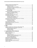
Intel Desktop Board D915GEV/D915GUX/D915GAV/D915GAG Product Guide Figure 2 shows the approximate location of the major components on desktop boards D915GAG and D915GUX. Line In RJ45 A BC D E V U F T G G B S Channel A Channel B G DIMM 0 DIMM 1 DIMM 0 DIMM 1 R Q OM K J P NL I H OM16861 - Intel D915GAG | User Manual - Page 15
• Intel Desktop Board D915GEV/D915GUX/ D915GAV/D915GAG • Supported processors http://www.intel.com/design/motherbd http://support.intel.com/support/motherboards/desktop http://support.intel.com/support/motherboards/desktop • Audio software and utilities http://www.intel.com/design/motherbd • LAN - Intel D915GAG | User Manual - Page 16
at: http://support.intel.com/support/motherboards/desktop/ Related Links: Go to the following links or pages for more information about: • Supported Intel processors for Desktop Board D915GEV/D915GUX/D915GAV/D915GAG http://support.intel.com/support/motherboards/desktop/ • Instructions on installing - Intel D915GAG | User Manual - Page 17
The desktop board supports dual or single channel memory configurations. Desktop boards D915GAV and D915GAG support dual or single channel memory configurations defined in Table 5. Table 5. Desktop Board D915GAV/D915GAG Memory Configurations Memory Speed DDR 400 Processor Pentium 4 processor DDR - Intel D915GAG | User Manual - Page 18
Intel Desktop Board D915GEV/D915GUX/D915GAV/D915GAG Product Guide Desktop boards D915GEV and D915GUX support dual or single channel memory configurations defined in Table 6. Table 6. Desktop Board D915GEV/D915GUX Memory Configurations Memory Speed Processor FSB frequency (MHz) Memory Speed - Intel D915GAG | User Manual - Page 19
Desktop Board Features Graphics Subsystem Desktop Board D915GEV/D915GUX/D915GAV/D915GAG includes the following: • Intel 915G Express Chipset • Intel Graphics Media Accelerator 900 • PCI Express x16 connector for graphics expansion Audio Subsystem Desktop Board D915GEV/D915GUX/D915GAV/D915GAG - Intel D915GAG | User Manual - Page 20
• Configurable EEPROM that contains the MAC address LAN Subsystem Software For LAN software and drivers, refer to the D915GEV/D915GUX/D915GAV/D915GAG link on Intel's World Wide Web site at: http://support.intel.com/support/motherboards/desktop RJ-45 LAN Connector LEDs Two LEDs are built into the - Intel D915GAG | User Manual - Page 21
Support NOTE Computer systems that have an unshielded cable attached to a USB port might not meet FCC Class B requirements, even if no device or a low-speed USB device is attached to the cable. Use a shielded cable that meets the requirements for a full-speed USB device. The desktop board supports - Intel D915GAG | User Manual - Page 22
Intel Desktop Board D915GEV/D915GUX/D915GAV/D915GAG Product Guide Enhanced IDE Interface The ICH6's IDE interface handles the exchange of information between the processor and peripheral devices like hard disks, CD-ROM drives, and Iomega Zip* drives inside the computer. The interface supports: • Up - Intel D915GAG | User Manual - Page 23
and a user password can be set for the BIOS Setup and USB ⎯ Wake from PS/2 keyboard/mouse ⎯ PME# wakeup support ACPI ACPI gives the operating system direct control over the power management and Plug and Play functions of a computer. The use of ACPI with the desktop board requires an operating system - Intel D915GAG | User Manual - Page 24
Intel Desktop Board D915GEV/D915GUX/D915GAV/D915GAG Product Guide Power Connectors The desktop boards have three power connectors. See Figure 25 on page 49 and Figure 26 on page 50 for the location of the power connectors. Fan Connectors The desktop boards have a 4-pin processor fan header. Desktop - Intel D915GAG | User Manual - Page 25
on standby current requirements for the desktop board, refer to the Technical Product Specification by going to the following link, finding the product, and selecting Product Documentation from the left-hand menu: http://support.intel.com/support/motherboards/desktop/ Resume on Ring The operation - Intel D915GAG | User Manual - Page 26
Intel Desktop Board D915GEV/D915GUX/D915GAV/D915GAG Product Guide Wake from USB NOTE Wake from USB requires the use of a USB peripheral that supports wake from USB. USB bus activity wakes the computer from an ACPI S1 or S3 state. Wake from PS/2 Keyboard/Mouse PS/2 keyboard/mouse activity wakes the - Intel D915GAG | User Manual - Page 27
desktop board • Install and remove a processor and memory • Install and remove a PCI Express x16 card • Connect the IDE and Serial ATA cables • Connect internal headers • Set up flexible 6-channel audio source and from any telecommunications links, networks, or modems before performing any of the - Intel D915GAG | User Manual - Page 28
Intel Desktop Board D915GEV/D915GUX/D915GAV/D915GAG Product Guide Installation Precautions When you install and test the Intel desktop board, observe all warnings and cautions in the installation instructions. To avoid injury, be careful of: • Sharp pins on connectors • Sharp pins on printed circuit - Intel D915GAG | User Manual - Page 29
The Industry Canada statement at the front of this product guide demonstrates compliance with Canadian EMC regulations. Industry Canada recognizes space on this Desktop Board to provide instructions for replacing and disposing of the Lithium ion coin cell battery. For system safety certification, the - Intel D915GAG | User Manual - Page 30
Intel Desktop Board D915GEV/D915GUX/D915GAV/D915GAG Product Guide Use Only for Intended Applications All Intel desktop boards are evaluated as Information Technology Equipment (I.T.E.) for use in personal computers for installation in homes, offices, schools, computer rooms, and similar locations. - Intel D915GAG | User Manual - Page 31
your chassis manual for instructions on installing and removing the desktop board. Figure 6 shows the location of the 11 mounting holes for desktop boards D915GAV and D915GEV. Desktop boards D915GAG and D916GUX have eight mounting holes. OM16893 Figure 6. Desktop Boards D915GEV and D915GAV Mounting - Intel D915GAG | User Manual - Page 32
Intel Desktop Board D915GEV/D915GUX/D915GAV/D915GAG Product Guide Installing and Removing a Processor Instructions on how to install the processor to the desktop board are given below. Installing a Processor CAUTION Before installing or removing the processor, make sure AC power has been removed by - Intel D915GAG | User Manual - Page 33
and Replacing Desktop Board Components 4. Remove the plastic protective socket cover from the load plate. Do not discard the protective socket cover. Always replace the socket cover if the processor is removed from the socket (see Figure 9, E). E Figure 9. Remove the Protective Socket Cover - Intel D915GAG | User Manual - Page 34
Fan Heat Sink Desktop Board D915GEV/D915GUX/D915GAV/D915GAG has an integrated processor fan heat sink retention mechanism (RM). For instructions on how to attach the processor fan heat sink to the integrated processor fan heat sink RM, refer to the boxed processor manual or the Intel World Wide Web - Intel D915GAG | User Manual - Page 35
Heat Sink Cable to the Processor Fan Connector Removing the Processor For instruction on how to remove the processor fan heat sink and processor, refer to the processor installation manual or the Intel World Wide Web site at: http://support.intel.com/support/processors/pentium4/intnotes478.htm 35 - Intel D915GAG | User Manual - Page 36
the PC Serial Presence Detect Specification at: http://www.intel.com/technology/memory/pcsdram/spec/ Desktop boards D915GAV and D915GAG have four 184-pin DDR DIMM sockets arranged as DIMM 0 (blue) and DIMM 1 (black) in both Channel A and Channel B. Desktop boards D915GEV and D915GUX have four 240 - Intel D915GAG | User Manual - Page 37
Installing and Replacing Desktop Board Components If additional memory is to be used, install another matched pair of DIMMs in DIMM 1 (black) in both A Channel B Figure 16. Dual Configuration Example 3 DIMM 0 DIMM 1 DIMM 0 DIMM 1 NOTE All other memory configurations will result in single channel - Intel D915GAG | User Manual - Page 38
Intel Desktop Board D915GEV/D915GUX/D915GAV/D915GAG Product Guide Installing DIMMs CAUTION Install memory in the DIMM sockets prior to installing the PCI Express video card to avoid interference with the memory retention mechanism. To make sure you have the correct DIMM, place the DIMM on the - Intel D915GAG | User Manual - Page 39
Installing and Replacing Desktop Board Components 1. Observe the precautions in "Before You Begin" on page 27. 2. Turn off all peripheral devices connected to the computer. Turn off the computer and disconnect the AC power cord. 3. Remove the computer's cover and locate the DIMM sockets (see Figure - Intel D915GAG | User Manual - Page 40
Intel Desktop Board D915GEV/D915GUX/D915GAV/D915GAG Product Guide Removing DIMMs To remove a DIMM, follow these steps: retaining clips at each end of the DIMM socket. The DIMM pops out of the socket. 7. Hold the DIMM by the edges, lift it away from the socket, and store it in an anti-static package - Intel D915GAG | User Manual - Page 41
Installing and Removing a PCI Express x16 Card CAUTION When installing any PCI Express x16 card on the desktop board, ensure that it is fully seated in the PCI Express x16 connector before you power on the system. If the card is not fully seated in the PCI Express connector, an electrical short may - Intel D915GAG | User Manual - Page 42
Intel Desktop Board D915GEV/D915GUX/D915GAV/D915GAG Product Guide Connecting the IDE Cable The IDE cable can connect two drives to the desktop board. The cable supports the ATA-66/100 transfer protocol. Figure 20 shows the correct installation of the cable. NOTE ATA-66/100 compatible cables are - Intel D915GAG | User Manual - Page 43
the Serial ATA (SATA) Cable The SATA cable (4-conductor) supports the Serial ATA protocol and connects a single drive to the desktop board. Either end of the cable can be connected to the SATA drive or the connector on the board. For correct cable function: 1. Observe the precaution in "Before - Intel D915GAG | User Manual - Page 44
Intel Desktop Board D915GEV/D915GUX/D915GAV/D915GAG Product Guide USB B 1 2 Power (+5V) 3 4 D5 6 D+ 7 8 Ground 10 N/C D 9 No Connection On/Off 87 65 Reset Power LED 43 HD LED 3 21 1 C B Item A B C D E Description Chassis intrusion Power LED Front panel USB 2.0 Front panel audio - Intel D915GAG | User Manual - Page 45
Installing and Replacing Desktop Board Components Installing a Front Panel Audio Solution Figure 22, E on page 44 shows the location of the yellow front panel audio header. Table 9 shows the pin assignments for the front panel audio header. Table 9. Front Panel Audio Header Signal Names Pin - Intel D915GAG | User Manual - Page 46
Intel Desktop Board D915GEV/D915GUX/D915GAV/D915GAG Product Guide Connecting USB 2.0 Headers Before connecting the USB 2.0 headers, observe the precautions in "Before You Begin" on page 27. See Figure 22, D on page 44 for the location of the black USB 2.0 headers. Table 10 shows the pin assignments - Intel D915GAG | User Manual - Page 47
Desktop Board Components Setting Up the Flexible 6-Channel Audio with Jack Re-tasking After installing the Realtek audio driver from the Intel Express Installer CD-ROM, the multichannel audio Back Panel Audio Connectors for Flexible 6-Channel Audio System Multi-Channel Analog Audio Connect two - Intel D915GAG | User Manual - Page 48
Intel Desktop Board D915GEV/D915GUX/D915GAV/D915GAG Product Guide Connecting Fan and Power Cables Connecting Fan Cables Figure 24 shows the location of the fan headers. Connect the processor's fan heat sink cable to the 4-pin processor fan header on the board. Connect chassis fan cables to the 3-pin - Intel D915GAG | User Manual - Page 49
Power Cables CAUTION Failure to use an ATX12V power supply, or not connecting the 12 V (2x2) processor core voltage power supply connector to the desktop board may result in damage to the desktop board and/or power supply. Connecting 2x10 Power Supply Cables The 2x12 main power connector on the - Intel D915GAG | User Manual - Page 50
Intel Desktop Board D915GEV/D915GUX/D915GAV/D915GAG Product Guide Connecting 2x12 Power Supply Cables If you have a 2x12 power supply, follow the instruction below. Figure 26 shows the location of the power connectors. 1 2 2X12 Figure 26. Connecting 2x12 Power Supply Cables 1. Observe the - Intel D915GAG | User Manual - Page 51
the PCI bus add-in card connectors, PCI Express x16 and x1 add-in card connectors, and peripheral interface connectors for desktop boards D915GAV and D915GEV. Desktop boards D915GUX and D915GAG have two PCI bus add-in card connectors, one PCI Express x16 and one PCI Express x1 add-in card connectors - Intel D915GAG | User Manual - Page 52
Intel Desktop Board D915GEV/D915GUX/D915GAV/D915GAG Product Guide Setting the BIOS Recovery (None) After the Power-On Self-Test (POST) runs, the BIOS displays the Maintenance Menu. Use this menu to clear passwords. The BIOS recovers data from a recovery diskette in the event of a failed BIOS update - Intel D915GAG | User Manual - Page 53
Installing and Replacing Desktop Board Components Clearing Passwords This procedure assumes that the board is installed in the computer and the configuration jumper block is set to normal mode. 1. Observe the precautions in "Before You Begin" on page 27. 2. - Intel D915GAG | User Manual - Page 54
Intel Desktop Board D915GEV/D915GUX/D915GAV/D915GAG Product Guide Back Panel Connectors NOTE The line out connector, located on the back panel, is designed to power either headphones or amplified speakers only. Poor audio quality may occur if passive (non-amplified) speakers are connected to this - Intel D915GAG | User Manual - Page 55
Installing and Replacing Desktop Board Components Replacing the Battery A coin-cell battery (CR2032) powers the real-time clock and CMOS memory. When the computer is not plugged into a wall socket, the battery has an estimated life of three years. When the computer is plugged in, the standby current - Intel D915GAG | User Manual - Page 56
Intel Desktop Board D915GEV/D915GUX/D915GAV/D915GAG Product Guide AVVERTIMENTO Esiste il pericolo di un esplosione se la pila non viene sostituita in modo corretto. Utilizzare solo pile uguali o di tipo equivalente a quelle consigliate - Intel D915GAG | User Manual - Page 57
Installing and Replacing Desktop Board Components AWAS Risiko letupan wujud jika bateri digantikan dengan jenis yang tidak betul. Bateri sepatutnya dikitar semula jika boleh. Pelupusan bateri terpakai mestilah mematuhi peraturan - Intel D915GAG | User Manual - Page 58
Intel Desktop Board D915GEV/D915GUX/D915GAV/D915GAG Product Guide O To replace the battery, follow these steps computer cover. 4. Locate the battery on the board (see Figure 30). 5. With a medium flat-bladed screwdriver, gently pry the battery free from its connector. Note the orientation of the - Intel D915GAG | User Manual - Page 59
BIOS with the Intel Express BIOS Update utility: 1. Go to the Intel World Wide Web site: http://support.intel.com/support/motherboards/desktop/ 2. Navigate to the D915GEV/D915GUX/D915GAV/D915GAG page, click "[view] Latest BIOS updates," and select the Express BIOS Update utility file. 3. Download - Intel D915GAG | User Manual - Page 60
• New BIOS files • BIOS recovery files • Intel Flash Memory Update Utility You can obtain the BIOS update file through your computer supplier or by navigating to the Desktop Board D915GEV/D915GUX/D915GAV/D915GAG page on the Intel World Wide Web site at: http://support.intel.com/support/motherboards - Intel D915GAG | User Manual - Page 61
steps explain how to recover the BIOS if an update fails. The following procedure uses recovery mode for the Setup program. See page 52 for more information on Setup modes. NOTE Because of the small amount of code available in the boot block area, there is no video support. You will not see anything - Intel D915GAG | User Manual - Page 62
Intel Desktop Board D915GEV/D915GUX/D915GAV/D915GAG Product Guide 62 - Intel D915GAG | User Manual - Page 63
TPM is specifically designed to shield unencrypted keys and platform authentication information from software-based attacks. System Requirements • Intel Desktop Board D915GEV or D915GUX with a Gigabit LAN solution • Microsoft Windows 2000 Professional (SP4) or Microsoft Windows XP Professional (SP1 - Intel D915GAG | User Manual - Page 64
Intel Desktop Board D915GEV/D915GUX/D915GAV/D915GAG Product Guide Security Precautions Security, like any other aspect of Recovery Token, and User passwords) and the Wave Systems EMBASSY Trust Suite are NOT RECOVERABLE and cannot be reset without the original text. The system owner should document - Intel D915GAG | User Manual - Page 65
, USB drive, CDR, flash media, etc). Once this is done, the removable media should be stored in a secure location. DO NOT LEAVE ANY COPIES of the Emergency Recovery Token on the hard drive or within any hard drive image backups. If a copy of the Emergency Recovery Token remains on the system, it - Intel D915GAG | User Manual - Page 66
Intel Desktop Board D915GEV/D915GUX/D915GAV/D915GAG Product Guide Trusted Platform Module Ownership The Trusted Platform Module is disabled by default when shipped and the owner/end customer of the system assumes "ownership" of the TPM. This permits the owner of the system to control initialization - Intel D915GAG | User Manual - Page 67
future. These documents and files should be updated after any password changes. Recovery Procedures How to Recover from Hard Disk Failure Restore the latest hard drive image from backup to the new hard drive - no TPM specific recovery is necessary. How to Recover from Desktop Board or TPM Failure - Intel D915GAG | User Manual - Page 68
Intel Desktop Board D915GEV/D915GUX/D915GAV/D915GAG Product Guide Requirements • Emergency Recovery Archive (created with the Infineon Security Platform Initiation Wizard) • Emergency Recovery Token (created with the Infineon Security Platform Initiation Wizard) • Emergency Recovery Token Security - Intel D915GAG | User Manual - Page 69
desktop board can continue to operate even though the front panel power switch is off. CAUTION DATA ENCRYPTED BY ANY PROGRAM UTILIZING THE TPM WILL BECOME INACCESSIBLE IF TPM OWNERSHIP IS CLEARED. Recovery the Wave System EMBASSY Trust Suite, visit the web at: http://www.wave.com/support/ets.html - Intel D915GAG | User Manual - Page 70
Intel Desktop Board D915GEV/D915GUX/D915GAV/D915GAG Product Guide 70 - Intel D915GAG | User Manual - Page 71
5 Desktop Board Resources Memory Map Table 13. System Memory Map Address Range (decimal) Memory Runtime BIOS Reserved Available high DOS memory (open to the PCI bus) Video memory and BIOS Extended BIOS data (movable by memory manager software) Extended conventional memory Conventional memory - Intel D915GAG | User Manual - Page 72
Intel Desktop Board D915GEV/D915GUX/D915GAV/D915GAG Product Guide Interrupts Table 15. Interrupts IRQ System Resource NMI I/O channel check 0 Reserved, interval timer 1 Reserved, keyboard buffer full 2 Reserved, cascade interrupt from slave PIC 3 COM2* (Plug and Play option) / ** 4 - Intel D915GAG | User Manual - Page 73
A Error Messages and Indicators Desktop Board D915GEV/D915GUX/D915GAV/D915GAG reports POST errors in two ways: • By sounding a beep code • By displaying an error message on the monitor BIOS Beep Codes The BIOS also issues a beep code (one long tone followed by two short tones) during POST if the - Intel D915GAG | User Manual - Page 74
Intel Desktop Board D915GEV/D915GUX/D915GAV/D915GAG Product Guide BIOS Error Messages When a recoverable error occurs during the POST, the BIOS displays an error message describing the problem. Table 17 gives an explanation of the BIOS error messages. Table 17. BIOS Error Messages Error Message - Intel D915GAG | User Manual - Page 75
boot. If no memory was removed, then memory may be bad. Memory size has increased since the last boot. If no memory was added, there may be a problem with the system. Memory size has changed since the last boot. If no memory was added or removed, then memory may be bad. System did not find a device - Intel D915GAG | User Manual - Page 76
Intel Desktop Board D915GEV/D915GUX/D915GAV/D915GAG Product Guide 76 - Intel D915GAG | User Manual - Page 77
Desktop Board D915GEV/D915GUX/D915GAV/D915GAG complies with the safety regulations stated in Table 18 when correctly installed in a compatible host system Statement We, Intel Corporation, declare under our sole responsibility that the product Intel® Desktop Board D915GEV/D915GUX/D915GAV/D915GAG is in - Intel D915GAG | User Manual - Page 78
Intel Desktop Board D915GEV/D915GUX/D915GAV/D915GAG Product Guide Dansk Dette produkt er i overensstemmelse med det europæiske direktiv 89/336/EEC & 73/23/EEC. Dutch Dit product is in navolging van de bepalingen - Intel D915GAG | User Manual - Page 79
Desktop Board D915GEV/D915GUX/D915GAV/D915GAG complies with the EMC regulations stated in Table 19 when correctly installed in a compatible host system interference. Install and use the equipment according to the instruction manual. Korean Class B statement translation: this is household equipment - Intel D915GAG | User Manual - Page 80
Intel Desktop Board D915GEV/D915GUX/D915GAV/D915GAG Product Guide Product Certification Markings (Board Level) Desktop Board D915GEV/D915GUX/D915GAV/D915GAG has the product certification markings shown in Table 20: Table 20. Product Certification Markings Description UL joint US/Canada Recognized
-
 1
1 -
 2
2 -
 3
3 -
 4
4 -
 5
5 -
 6
6 -
 7
7 -
8
-
9
-
10
-
11
-
12
-
13
-
14
-
15
-
16
-
17
-
18
-
19
-
20
-
21
-
22
-
23
-
24
-
25
-
26
-
27
-
28
-
29
-
30
-
31
-
32
-
33
-
34
-
35
-
36
-
37
-
38
-
39
-
40
-
41
-
42
-
43
-
44
-
45
-
46
-
47
-
48
-
49
-
50
-
51
-
52
-
53
-
54
-
55
-
56
-
57
-
58
-
59
-
60
-
61
-
62
-
63
-
64
-
65
-
66
-
67
-
68
-
69
-
70
-
71
-
72
-
73
-
74
-
75
-
76
-
77
-
78
-
79
-
80
 |
 |
Intel
®
Desktop Board
D915GEV/D915GUX/
D915GAV/D915GAG
Product Guide
Order Number:
C64136-002