Intel D915GEV User Manual - Page 44
Connecting Internal Headers
 |
UPC - 735858177559
View all Intel D915GEV manuals
Add to My Manuals
Save this manual to your list of manuals |
Page 44 highlights
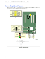
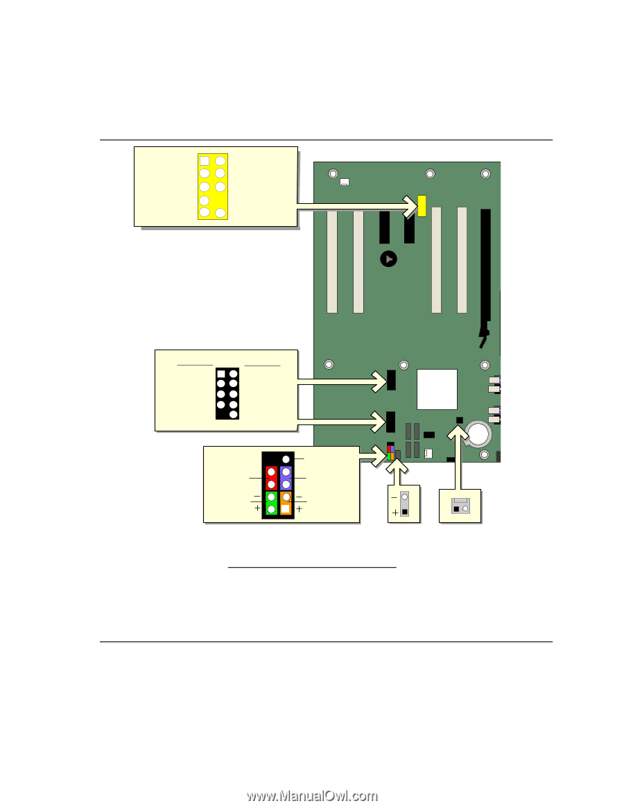
Intel Desktop Board D915GEV/D915GUX/D915GAV/D915GAG Product Guide Connecting Internal Headers Before connecting cables to the internal headers, observe the precautions in "Before You Begin" on page 27. Figure 22 shows the location of the internal headers. Port1L Port1R Port2R Sense_Send Port2L 12 34 56 7 9 10 GND Presence# Sense1_Ret Key (no pin) Sense2_Ret E USB A Power (+5V) DD+ Ground Key (no pin) USB B 1 2 Power (+5V) 3 4 D5 6 D+ 7 8 Ground 10 N/C D 9 No Connection On/Off 87 65 Reset Power LED 43 HD LED 3 21 1 C B Item A B C D E Description Chassis intrusion Power LED Front panel USB 2.0 Front panel audio Figure 22. Internal Headers 1 A OM16918 44
-
 1
1 -
2
-
3
-
4
-
5
-
6
-
7
-
8
-
9
-
10
-
11
-
12
-
13
-
14
-
15
-
16
-
17
-
18
-
19
-
20
-
21
-
22
-
23
-
24
-
25
-
26
-
27
-
28
-
29
-
30
-
31
-
32
-
33
-
34
-
35
-
36
-
37
-
38
-
 39
39 -
 40
40 -
 41
41 -
 42
42 -
 43
43 -
 44
44 -
 45
45 -
 46
46 -
 47
47 -
 48
48 -
 49
49 -
50
-
51
-
52
-
53
-
54
-
55
-
56
-
57
-
58
-
59
-
60
-
61
-
62
-
63
-
64
-
65
-
66
-
67
-
68
-
69
-
70
-
71
-
72
-
73
-
74
-
75
-
76
-
77
-
78
-
79
-
80
 |
 |
Intel Desktop Board D915GEV/D915GUX/D915GAV/D915GAG Product Guide
44
Connecting Internal Headers
Before connecting cables to the internal headers, observe the precautions in "Before You Begin" on
page 27.
Figure 22 shows the location of the internal headers.
OM16918
D
B
C
1
5
6
7
3
4
2
10
9
Port1L
Port1R
Port2R
Sense_Send
Port2L
GND
Presence#
Sense1_Ret
Key (no pin)
Sense2_Ret
1
3
On/Off
Power LED
HD LED
Reset
No Connection
1
2
3
4
5
7
6
8
9
USB A
USB B
1
5
6
7
8
3
4
2
10
Power (+5V)
Power (+5V)
D-
D+
Ground
Key (no pin)
N/C
D-
D+
Ground
E
A
1
Item
Description
A
Chassis intrusion
B
Power LED
C
Front panel
D
USB 2.0
E
Front panel audio
Figure 22.
Internal Headers