Intel D915GEV User Manual - Page 45
Installing a Front Panel Audio Solution
 |
UPC - 735858177559
View all Intel D915GEV manuals
Add to My Manuals
Save this manual to your list of manuals |
Page 45 highlights
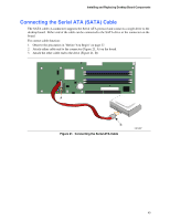
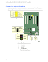
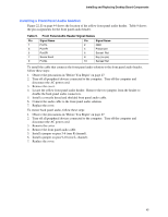
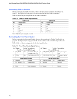
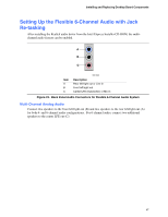
Installing and Replacing Desktop Board Components Installing a Front Panel Audio Solution Figure 22, E on page 44 shows the location of the yellow front panel audio header. Table 9 shows the pin assignments for the front panel audio header. Table 9. Front Panel Audio Header Signal Names Pin Signal Name 1 Port1L 3 Port1R 5 Port2R 7 Sense Send 9 Port2L Pin Signal Name 2 GND 4 Presence# 6 Sense1 Ret 8 Key (no pin) 10 Sense2 Ret To install the cable that connects the front panel audio solution to the front panel audio header, follow these steps: 1. Observe the precautions in "Before You Begin" on page 27. 2. Turn off all peripheral devices connected to the computer. Turn off the computer and disconnect the AC power cord. 3. Remove the cover. 4. Locate the yellow front panel audio header. Remove the two jumpers from the header to disable the back panel audio connectors. 5. Install a correctly keyed and shielded front panel audio cable. 6. Connect the audio cable to the front panel audio solution. 7. Replace the cover. To restore back panel audio, follow these steps: 1. Observe the precautions in "Before You Begin" on page 27. 2. Turn off all peripheral devices connected to the computer. Turn off the computer and disconnect the AC power cord. 3. Remove the cover. 4. Remove the front panel audio cable. 5. Install a jumper on pins 5-6 (rear R channel). 6. Install a jumper on pins 9-10 (rear L channel). 7. Replace the cover. 45
-
 1
1 -
2
-
3
-
4
-
5
-
6
-
7
-
8
-
9
-
10
-
11
-
12
-
13
-
14
-
15
-
16
-
17
-
18
-
19
-
20
-
21
-
22
-
23
-
24
-
25
-
26
-
27
-
28
-
29
-
30
-
31
-
32
-
33
-
34
-
35
-
36
-
37
-
38
-
39
-
 40
40 -
 41
41 -
 42
42 -
 43
43 -
 44
44 -
 45
45 -
 46
46 -
 47
47 -
 48
48 -
 49
49 -
 50
50 -
51
-
52
-
53
-
54
-
55
-
56
-
57
-
58
-
59
-
60
-
61
-
62
-
63
-
64
-
65
-
66
-
67
-
68
-
69
-
70
-
71
-
72
-
73
-
74
-
75
-
76
-
77
-
78
-
79
-
80
 |
 |