Intel D915PBL Product Guide
Intel D915PBL - 915P Socket 775 ATX Motherboard Manual
 |
UPC - 683728095185
View all Intel D915PBL manuals
Add to My Manuals
Save this manual to your list of manuals |
Intel D915PBL manual content summary:
- Intel D915PBL | Product Guide - Page 1
Intel® Desktop Board D915PBL Product Guide Order Number: C64182-001 - Intel D915PBL | Product Guide - Page 2
and used in accordance with the instructions, may cause harmful interference to radio by turning the equipment off and on, the user is encouraged to try to correct the interference by Intel may make changes to specifications and product descriptions at any time, without notice. Desktop Board D915PBL - Intel D915PBL | Product Guide - Page 3
Preface This Product Guide gives information about board layout, component installation, BIOS Setup menus, and regulatory requirements for Intel® Desktop Board D915PBL. Intended Audience The Product Guide is intended for technically qualified personnel. It is not intended for general audiences. - Intel D915PBL | Product Guide - Page 4
• Intel® Desktop Board • I/O shield • One ATA-66/100 cable • Four Serial ATA cables • Two Serial ATA power cables • One diskette drive cable • One rear panel USB 2.0/IEEE 1394 adapter • One front panel USB 2.0/IEEE 1394/audio adapter • Intel® Express Installer CD-ROM • Floppy disk with RAID driver - Intel D915PBL | Product Guide - Page 5
Board Features Supported Operating Systems 10 Desktop Board Components 11 Processor ...13 Main Memory ...14 Intel® 915P Express Chipset 15 Audio Subsystem ...15 Input/Output (I/O) Controller 16 LAN Subsystem ...16 LAN Subsystem Software 16 RJ-45 LAN Connector LEDs 16 Hi-Speed USB 2.0 Support - Intel D915PBL | Product Guide - Page 6
the BIOS for Intel Matrix Storage Technology 40 Creating your RAID set 40 Loading the Intel® Application Accelerator Drivers 40 Setting Up a "RAID Ready" System 40 Connecting Internal Headers 41 Front Panel Audio Header 42 IEEE 1394 Headers...42 USB 2.0 Headers ...42 Front Panel Header - Intel D915PBL | Product Guide - Page 7
BIOS Beep Codes...65 BIOS Error Messages ...65 B Regulatory Compliance Safety Regulations ...67 European Union Declaration of Conformity Statement 67 Product Ecology Statements 68 EMC Regulations ...69 Product Certification Markings (Board Level 70 Figures 1. Desktop Board D915PBL Components - Intel D915PBL | Product Guide - Page 8
Intel Desktop Board D915PBL Product Guide Tables 1. Feature Summary ...9 2. Desktop Board D915PBL Components 12 3. Memory Configurations 14 4. RJ-45 10/100 Ethernet LAN Connector LEDs 16 5. Front Panel Audio Header Signal Names 42 6. IEEE 1394 Header Signal Names 42 7. USB 2.0 Header Signal - Intel D915PBL | Product Guide - Page 9
of Intel® Desktop Board D915PBL. Table 1 summarizes the major features of the desktop board. Table 1. Feature Summary Form Factor Processor Main Memory Chipset Audio Expansion Capabilities LAN Subsystem BIOS RAID ATX (12.00" x 9.60") Support for an Intel® Pentium® 4 processor in the LGA775 - Intel D915PBL | Product Guide - Page 10
about Intel Desktop Board D915PBL, including the Technical Product Specification (TPS), BIOS updates, and device drivers, go to: http://support.intel.com/support/motherboards/desktop/ Supported Operating Systems The desktop board supports the following operating systems: • Microsoft Windows* XP - Intel D915PBL | Product Guide - Page 11
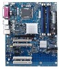
1 shows the approximate location of the major components on Desktop Board D915PBL. Line In IEEE 1394 RJ45 Optical Line Out (Toslink) Co-axial Line Out AB CD W E F V G U Intel 82915P T (MCH) H Channel A Intel DIMM 0 S 82801FR (ICH6-R) Channel B DIMM 1 DIMM 0 DIMM 1 R P NL - Intel D915PBL | Product Guide - Page 12
• Intel Desktop Board D915PBL http://www.intel.com/design/motherbd http://support.intel.com/support/motherboards/desktop • Supported processors http://support.intel.com/support/motherboards/desktop • Audio software and utilities http://www.intel.com/design/motherbd • LAN software and drivers - Intel D915PBL | Product Guide - Page 13
to the Intel desktop board through the LGA775 socket. The supported processors list for Desktop Board D915PBL is located on the web at: http://support.intel.com/support/motherboards/desktop/ Related Links Go to the following links or pages for more information about: • Instructions on installing - Intel D915PBL | Product Guide - Page 14
up. The BIOS will attempt to configure the memory controller for normal operation. The desktop board supports dual or single channel memory configurations defined in Table 3. Table 3. Memory Configurations Memory Speed DDR2 533 Processor Pentium 4 processor DDR2 400 Pentium 4 processor FSB - Intel D915PBL | Product Guide - Page 15
• Intel 82915P Memory Controller Hub (MCH) with Direct Media Interface • Intel 82801FR I/O Controller Hub (ICH6-R) Related Link Go to the following link for more information about the Intel 915P Express Chipset: http://developer.intel.com/design/nav/pcserver.htm Audio Subsystem Desktop Board D915PBL - Intel D915PBL | Product Guide - Page 16
drivers, refer to the D915PBL link on Intel's World Wide Web site at: http://support.intel.com/support/motherboards/desktop RJ-45 LAN Connector LEDs Table 4 describes the LED states when the board is powered up and the 10/100 Ethernet LAN subsystem is operating. Table 4. RJ-45 10/100 Ethernet LAN - Intel D915PBL | Product Guide - Page 17
100 protocols • Laser Servo (LS-120) drives Serial ATA The desktop board supports four Serial ATA channels via the ICH6-R, connecting one device per channel in either a RAID or non-RAID configuration. Expandability Desktop board D915PBL supports the following: • One PCI Express x16 add-in card • Two - Intel D915PBL | Product Guide - Page 18
Intel Desktop Board D915PBL Product Guide BIOS The BIOS provides the Power-On Self-Test (POST), the BIOS Setup program, the PCI and IDE auto-configuration utilities, and the video BIOS. See Chapter 3 on page 59 for more information about the BIOS. Serial ATA and IDE Auto Configuration If you install - Intel D915PBL | Product Guide - Page 19
desktop board BIOS. Disabling the processor fan speed control will result in the fan operating at full speed if it is not a self controlled fan. It is recommended that processor fan speed control remain enabled (default BIOS setting) when using the processor fan heat-sink included with Intel boxed - Intel D915PBL | Product Guide - Page 20
awake state. The desktop board's standby power indicator, shown in Figure 2, is lit when there is standby power to the system. This includes the memory modules and PCI bus connectors, even when the computer appears to be off. If the system has a dual-colored power LED on the front panel, the sleep - Intel D915PBL | Product Guide - Page 21
. The speaker provides audible error code (beep code) information during the Power-On Self-Test (POST). Battery A battery on the desktop board keeps the values in CMOS RAM and the clock current when the computer is turned off. See Chapter 2 starting on page 23 for instructions on how to replace the - Intel D915PBL | Product Guide - Page 22
Intel Desktop Board D915PBL Product Guide 22 - Intel D915PBL | Product Guide - Page 23
the desktop board • Install and remove a processor and memory • Install and remove a PCI Express x16 card • Connect the IDE and Serial ATA cables • Configure your system for Intel Matrix Storage Technology for Serial ATA • Connect internal headers • Install the rear and front panel USB/IEEE/audio - Intel D915PBL | Product Guide - Page 24
test the Intel desktop board, observe all warnings and cautions in the installation instructions. To avoid injury, be careful of: • Sharp pins on connectors • Sharp pins on printed circuit assemblies • Rough edges and sharp corners on the chassis • Hot components (like processors, voltage regulators - Intel D915PBL | Product Guide - Page 25
requirements. The Industry Canada statement at the front of this product guide demonstrates compliance with Canadian EMC regulations. Industry . Place Battery Marking There is insufficient space on this Desktop Board to provide instructions for replacing and disposing of the Lithium ion coin cell - Intel D915PBL | Product Guide - Page 26
Intel Desktop Board D915PBL Product Guide Use Only for Intended Applications All Intel desktop boards are evaluated as Information Technology Equipment (I.T.E.) for use in personal computers for installation in homes, offices, schools, computer rooms, and similar locations. The suitability of - Intel D915PBL | Product Guide - Page 27
damage. NOTE Refer to Appendix B for regulatory requirements. Refer to your chassis manual for instructions on installing and removing the desktop board. Figure 4 shows the location of the 10 mounting holes for Desktop Board D915PBL. Figure 4. Location of Desktop Board Mounting Holes OM16982 27 - Intel D915PBL | Product Guide - Page 28
Intel Desktop Board D915PBL Product Guide Installing and Removing a Processor Instructions on how to install the processor to the desktop board are given below. Installing a Processor CAUTION Before installing or removing the processor, make sure that AC power has been removed by unplugging the - Intel D915PBL | Product Guide - Page 29
Desktop Board Components 4. Remove the protective socket cover from the load plate. Do not discard the protective socket cover. Always replace the socket cover if the processor is removed from the socket (see Figure 7, E). E Figure 7. Remove the Protective Socket Cover 5. Remove the processor - Intel D915PBL | Product Guide - Page 30
Sink Desktop Board D915PBL has an integrated processor fan heat sink retention mechanism (RM). For instructions on how to attach the processor fan heat sink to the integrated processor fan heat sink RM, refer to the boxed processor manual or the Intel World Wide Web site at: http://support.intel.com - Intel D915PBL | Product Guide - Page 31
Fan Heat Sink Cable to the Processor Fan Header Removing the Processor For instruction on how to remove the processor fan heat sink and processor, refer to the processor installation manual or the Intel World Wide Web site at: http://support.intel.com/support/processors/pentium4/intnotes478.htm 31 - Intel D915PBL | Product Guide - Page 32
the Serial Presence Detect (SPD) data structure. You can access the PC Serial Presence Detect Specification at: http://www.intel.com/technology/memory/pcsdram/spec/ Desktop Board D915PBL has four 240-pin DIMM sockets arranged as DIMM 0 and DIMM 1 in both Channel A and Channel B, as shown in Figure - Intel D915PBL | Product Guide - Page 33
Installing and Replacing Desktop Board Components Three DIMMs Install a matched pair of DIMMs equal in speed and size in DIMM 0 (blue) and , 400 MHz Channel A DIMM 0 DIMM 1 DIMM 0 DIMM 1 Figure 14. Dual Configuration Example 3 NOTE All other memory configurations will result in single channel - Intel D915PBL | Product Guide - Page 34
Intel Desktop Board D915PBL Product Guide Installing DIMMs CAUTION Install memory in the DIMM sockets prior to installing the PCI Express x16 card to avoid interference with the memory retention mechanism. To make sure you have the correct DIMM, place the DIMM on the illustration in Figure 15 - Intel D915PBL | Product Guide - Page 35
Desktop Board Components To install DIMMs, follow these steps: 1. Observe the precautions in "Before You Begin" on page 23. 2. Turn off all peripheral devices connected to the computer. Turn off the computer and disconnect the AC power cord. 3. Remove the computer's cover and locate the DIMM sockets - Intel D915PBL | Product Guide - Page 36
Intel Desktop Board D915PBL Product Guide Removing DIMMs To remove a memory module, board components and/or traces may be damaged. The desktop board has an integrated PCI Express x16 card retention mechanism (RM). Installing a PCI Express x16 Card Follow these instructions panel with a screw. 36 - Intel D915PBL | Product Guide - Page 37
and Replacing Desktop Board Components Removing the PCI Express x16 Card Follow these instructions to remove the PCI Express x16 card from the RM: 1. Observe the precautions in "Before You Begin" on page 23. 2. Remove the screw that secures the card's metal bracket to the chassis back panel (Figure - Intel D915PBL | Product Guide - Page 38
Intel Desktop Board D915PBL Product Guide Connecting the IDE Cable The IDE cable can connect two drives to the desktop board. The cable supports the ATA-66/100 transfer protocol. Figure 18 shows the correct installation of the cable. NOTE ATA-66/100 compatible cables are backward compatible with - Intel D915PBL | Product Guide - Page 39
Components Connecting the Serial ATA Cable The SATA cable (4-conductor) supports the Serial ATA protocol and connects a single drive to the desktop board. Either end of the cable can be connected to the SATA drive or the connector on the board. For correct cable function: 1. Observe the precaution - Intel D915PBL | Product Guide - Page 40
disk labeled RAID Driver. Install the Intel 82801FR SATA RAID Controller driver. 3. Finish the Windows installation and install all necessary drivers. 4. Install the Intel Application Accelerator software via the Intel Express Installer CD included with your desktop board or after downloading it - Intel D915PBL | Product Guide - Page 41
Installing and Replacing Desktop Board Components Connecting Internal Headers Before connecting cables to LED 43 HD LED 3 21 1 C B Item A B C D E F Description Chassis intrusion Alternate power LED Front panel USB 2.0 IEEE 1394 Front panel audio Figure 20. Internal Headers 1 A OM16964 41 - Intel D915PBL | Product Guide - Page 42
Intel Desktop Board D915PBL Product Guide Front Panel Audio Header Figure 20, F on page 41 shows the location of the yellow front panel audio header. Table 5 shows the pin assignments for the front panel audio header. Table 5. Front Panel Audio Header Signal Names Pin Signal Name 1 Port1L 3 - Intel D915PBL | Product Guide - Page 43
Installing and Replacing Desktop Board Components Front Panel Header Figure 20, C on page 41 shows the location of the multi-colored front panel header. Table 8 shows the pin assignments for the front panel header. Table 8. Front Panel Header Signal Names Pin Signal In/Out Description Hard - Intel D915PBL | Product Guide - Page 44
Intel Desktop Board D915PBL Product Guide Installing the Rear Panel USB 2.0 and IEEE 1394 Adapters Follow these instructions to install the rear panel USB 2.0 and IEEE 1394 adapter (see Figure 21): 1. Observe the precautions in "Before You Begin" on page 23. 2. Attach the cable end with the - Intel D915PBL | Product Guide - Page 45
keyed and shielded cable. 6. Connect the cables to their respective headers on the desktop board. 7. Replace the cover. OM16963 Figure 22. Connecting the Front Panel USB/IEEE1394/Audio Cables To restore back panel audio, follow these steps: 1. Observe the precautions in "Before You Begin" on page 23 - Intel D915PBL | Product Guide - Page 46
Intel Desktop Board D915PBL Product Guide Connecting Fans and Power Cables Connecting Fans See Figure 23 for fan header locations. Connect the processor's fan heat sink cable to the 4-pin processor fan header on the board. Connect chassis fan cables to the board fan headers. 3 21 A 3 21 B 43 2 1 - Intel D915PBL | Product Guide - Page 47
Power Cables CAUTION Failure to use an ATX12V power supply, or not connecting the 12 V processor core voltage power supply connector (2x2) to the desktop board may result in damage to the desktop board and/or power supply. Connecting 2x10 Power Supply Cables The 2x12 main power connector on the - Intel D915PBL | Product Guide - Page 48
Intel Desktop Board D915PBL Product Guide Connecting 2x12 Power Supply Cables If you have a 2x12 power supply, follow the instruction below. Figure 25 shows the location of the power connectors for a 2x12 power supply. 1 2 Figure 25. Connecting 2x12 Power Supply Cables OM16965 1. Observe the - Intel D915PBL | Product Guide - Page 49
Installing and Replacing Desktop Board Components Installing Other Connectors Figure 26 shows the location of the: • PCI bus add-in card connectors • PCI Express x1 connectors • PCI Express x16 connector • - Intel D915PBL | Product Guide - Page 50
Intel Desktop Board D915PBL Product Guide Setting the BIOS Configuration Jumper Block CAUTION Always turn off the power and unplug the power cord from the computer before changing the jumper. Moving the jumper with the power on may result in unreliable computer operation. The location of the desktop - Intel D915PBL | Product Guide - Page 51
Installing and Replacing Desktop Board Components Clearing Passwords This procedure assumes that the board is installed in the Replace the cover, plug in the computer, turn on the computer, and allow it to boot. 7. The computer starts the Setup program. Setup displays the Maintenance menu. 8. Use the - Intel D915PBL | Product Guide - Page 52
Intel Desktop Board D915PBL Product Guide Back Panel Connectors NOTE The line out connector, located on the back panel, is designed to power either headphones or amplified speakers only. Poor audio quality may occur if passive (non-amplified) speakers are connected to this output. Figure 28 shows - Intel D915PBL | Product Guide - Page 53
Installing and Replacing Desktop Board Components Setting Up Full 7.1-Channel Surround Sound (Optional) After installing the audio driver from the Intel Express Installer CD-ROM, the multi-channel audio feature can be enabled. Figure 29 shows the location of back panel audio connectors. AB C Item A - Intel D915PBL | Product Guide - Page 54
Intel Desktop Board D915PBL Product Guide Replacing the Battery A coin-cell battery (CR2032) powers the real-time clock and CMOS memory. When the computer is not plugged into a wall socket drops below a certain level, the BIOS Setup program settings stored in CMOS RAM (for example, the date and time - Intel D915PBL | Product Guide - Page 55
Installing and Replacing Desktop Board Components AVVERTIMENTO Esiste il pericolo di un esplosione se la pila non viene sostituita in modo corretto. Utilizzare solo pile uguali o di tipo equivalente a quelle - Intel D915PBL | Product Guide - Page 56
Intel Desktop Board D915PBL Product Guide AWAS Risiko letupan wujud jika bateri digantikan dengan jenis yang tidak betul. Bateri sepatutnya dikitar semula jika boleh. Pelupusan bateri terpakai mestilah mematuhi peraturan alam - Intel D915PBL | Product Guide - Page 57
Installing and Replacing Desktop Board Components UYARI Yanl†‡ türde pil tak†ld†‰†nda patlama riski source (wall outlet or power adapter). 3. Remove the computer cover. 4. Locate the battery on the board (see Figure 30). 5. With a medium flat-bladed screwdriver, gently pry the battery free from its - Intel D915PBL | Product Guide - Page 58
Intel Desktop Board D915PBL Product Guide 58 - Intel D915PBL | Product Guide - Page 59
) memory test begins and before the operating system boot begins. The BIOS identifier for this desktop board is CY91510A.86A. For the latest BIOS Setup menu options, go to the Intel World Wide Web site: http://support.intel.com/support/motherboards/desktop/ Updating the BIOS The BIOS can be updated - Intel D915PBL | Product Guide - Page 60
navigating to the Desktop Board D915PBL page on the Intel World Wide Web site at: http://support.intel.com/support/motherboards/desktop Navigate to the D915PBL page, click "[view] Latest BIOS updates," and select the Iflash BIOS Update utility file. NOTE Review the instructions distributed with the - Intel D915PBL | Product Guide - Page 61
steps explain how to recover the BIOS if an update fails. The following procedure uses recovery mode for the Setup program. See page 50 for more information on Setup modes. NOTE Because of the small amount of code available in the boot block area, there is no video support. You will not see anything - Intel D915PBL | Product Guide - Page 62
Intel Desktop Board D915PBL Product Guide 62 - Intel D915PBL | Product Guide - Page 63
4 Desktop Board Resources Memory Map Table 10. System Memory Map Address Range (decimal) Memory Runtime BIOS Reserved Available high DOS memory (open to the PCI bus) Video memory and BIOS Extended BIOS data (movable by memory manager software) Extended conventional memory Conventional memory - Intel D915PBL | Product Guide - Page 64
Intel Desktop Board D915PBL Product Guide Interrupts Table 12. Interrupts IRQ System Resource NMI I/O channel check else user available) 13 Reserved, math coprocessor 14 Primary IDE/Serial ATA (if present, else user available) 15 Secondary IDE/Serial ATA (if present, else user available) - Intel D915PBL | Product Guide - Page 65
Desktop Board D915PBL reports POST errors in two ways: • By sounding a beep code • By displaying an error message on the monitor BIOS Beep Codes The BIOS beep codes are listed in Table 13. The BIOS also issues a beep code (one long tone followed by two short tones) during POST if the video - Intel D915PBL | Product Guide - Page 66
Intel Desktop Board D915PBL Product Guide Table 14. BIOS Error Messages (continued) Error Message CMOS Date/Time Not Set Explanation The time and/or date values stored in CMOS are invalid. Run Setup to - Intel D915PBL | Product Guide - Page 67
- Safety - Part 1: General Requirements (International) European Union Declaration of Conformity Statement We, Intel Corporation, declare under our sole responsibility that the product Intel® Desktop Board D915PBL is in conformity with all applicable essential requirements necessary for CE marking - Intel D915PBL | Product Guide - Page 68
Intel Desktop Board D915PBL Product Guide Dansk Dette produkt er i overensstemmelse med det europæiske direktiv 89/336/EEC & 73/23/EEC. Dutch Dit product is in navolging van de bepalingen - Intel D915PBL | Product Guide - Page 69
Regulations Desktop Board D915PBL complies with B) CISPR 24: 1997 VCCI (Class B) Title Title 47 of the Code of Federal Regulations, Parts 2 and 15, Subpart B, Radio Frequency Devices Install and use the equipment according to the instruction manual. Korean Class B statement translation: this is - Intel D915PBL | Product Guide - Page 70
Intel desktop boards: E210882 (component side). Mark FCC Declaration of Conformity logo mark for Class B equipment; includes Intel name and D915PBL Includes adjacent Intel supplier code number, N-232. The C-tick mark should also be on the shipping container. Printed wiring board manufacturer's
-
 1
1 -
 2
2 -
 3
3 -
 4
4 -
 5
5 -
 6
6 -
 7
7 -
8
-
9
-
10
-
11
-
12
-
13
-
14
-
15
-
16
-
17
-
18
-
19
-
20
-
21
-
22
-
23
-
24
-
25
-
26
-
27
-
28
-
29
-
30
-
31
-
32
-
33
-
34
-
35
-
36
-
37
-
38
-
39
-
40
-
41
-
42
-
43
-
44
-
45
-
46
-
47
-
48
-
49
-
50
-
51
-
52
-
53
-
54
-
55
-
56
-
57
-
58
-
59
-
60
-
61
-
62
-
63
-
64
-
65
-
66
-
67
-
68
-
69
-
70
 |
 |

Intel
®
Desktop Board
D915PBL Product Guide
Order Number:
C64182-001