Intel D915PGNL Product Guide
Intel D915PGNL - Desktop Board Motherboard Manual
 |
UPC - 735858178204
View all Intel D915PGNL manuals
Add to My Manuals
Save this manual to your list of manuals |
Intel D915PGNL manual content summary:
- Intel D915PGNL | Product Guide - Page 1
Intel® Desktop Board D915PGN/D915PSY/ D915PCY/D915PCM Product Guide Order Number: C64156-001 - Intel D915PGNL | Product Guide - Page 2
the Intel® Desktop Board D915PGN/D915PSY/D915PCY/D915PCM Product Guide. Date Intel literature, may be obtained from Intel Corporation by going to the World Wide Web site at: http://www.intel.com/ or by calling 1-800-548-4725. Intel, Pentium, and Celeron are registered trademarks of Intel Corporation - Intel D915PGNL | Product Guide - Page 3
Intel® Desktop Board D915PGN/D915PSY/ D915PCY/D915PCM. Intended Audience The Product Guide : instructions on how to install the desktop board and other hardware components • 3 BIOS: instructions on The following conventions are used in this manual: WARNING Warnings indicate conditions that, if - Intel D915PGNL | Product Guide - Page 4
048,576 bytes) Megabit (1,048,576 bits) Megahertz (one million hertz) Box Contents • Intel Desktop Board • I/O shield • One IDE cable • Two Serial ATA cables • One diskette drive cable • Quick Reference Guide • Configuration and battery caution statement label • Intel® Express Installer CD-ROM iv - Intel D915PGNL | Product Guide - Page 5
Manufacturing Options ...11 Supported Operating Systems 11 Desktop Board Components 12 Processor ...16 Main Memory ...17 Intel® 915P Express Chipset You Begin ...27 Installation Precautions ...28 Installation Instructions...28 Ensure Electromagnetic Compatibility (EMC) Compliance 28 Chassis - Intel D915PGNL | Product Guide - Page 6
Intel Desktop Board D915PGN/D915PSY/D915PCY/D915PCM Product Guide Installing the I/O Shield ...30 Installing and Removing the Desktop Board 31 Installing and Removing a Processor 32 Installing a Processor 32 Installing the Processor Fan Heat Sink 34 Connecting the Processor Fan Heat Sink Cable - Intel D915PGNL | Product Guide - Page 7
Board Level 72 Figures 1. Desktop Boards D915PGN and D915PCY Components 12 2. Intel Desktop Boards D915PSY and D915PCM Components 14 Processor from the Protective Cover 33 10. Install Processor ...34 11. Close the Load Plate ...34 12. Connecting the Processor Fan Heat Sink Cable to the Processor - Intel D915PGNL | Product Guide - Page 8
Intel Desktop Board D915PGN/D915PSY/D915PCY/D915PCM Product Guide 9. USB 2.0 Header Signal Names 46 10. Front Panel Header Signal Names 46 11. Jumper Settings for the BIOS Setup Program Modes 52 12. System Memory - Intel D915PGNL | Product Guide - Page 9
/D915PCM. Table 1 summarizes the major features of the desktop board. Table 1. Feature Summary Processor Support for an Intel® Pentium® 4 processor in the LGA775 package Main Memory Desktop boards D915PGN and D915PSY: • Four 184-pin, 2.5 V SDRAM Dual Inline Memory Module (DIMM) sockets • 400 - Intel D915PGNL | Product Guide - Page 10
• Voltage sensing to detect out of range values Related Links For more information about Intel Desktop Board D915PGN/D915PSY/D915PCY/D915PCM, including the Technical Product Specification (TPS), BIOS updates, and device drivers, go to: http://support.intel.com/support/motherboards/desktop/ 10 - Intel D915PGNL | Product Guide - Page 11
option for Desktop Board D915PGN/D915PSY/ D915PCY/D915PCM. Table 2. Option LAN Manufacturing Option Description Intel® 82562EZ 10/100 Mbit/sec Platform LAN Connect (PLC) device with RJ-45 connector Supported Operating Systems The desktop board supports the following operating systems - Intel D915PGNL | Product Guide - Page 12
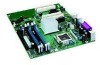
Intel Desktop Board D915PGN/D915PSY/D915PCY/D915PCM Product Guide Desktop Board Components Figure 1 shows the approximate location of the major components on Desktop Board D915PGN and D915PCY. Line In RJ45 AB CD V E F U G T H Channel A DIMM 0 B DIMM 1 S Channel B DIMM 0 DIMM 1 Q NL R - Intel D915PGNL | Product Guide - Page 13
U V Desktop Boards D915PGN and D915PCY Components Description PCI Express x1 connectors Front panel audio header PCI Express x16 connector Rear chassis fan header 1 (fan speed control) Alternate power connector (1x4) 12 V processor core voltage connector (2x2) Processor socket Processor fan header - Intel D915PGNL | Product Guide - Page 14
Board D915PGN/D915PSY/D915PCY/D915PCM Product Guide Figure 2 shows the approximate location of the major components on Desktop Boards D915PSY and D915PCM. Line In RJ45 A BC D E U T S F B R Q Channel A Channel B G DIMM 0 DIMM 1 DIMM 0 DIMM 1 O MK P NL J IH OM16848 Figure 2. Intel - Intel D915PGNL | Product Guide - Page 15
links for more information about: • Intel Desktop Board D915PGN/D915PSY/ D915PCY/D915PCM http://www.intel.com/design/motherbd http://support.intel.com/support/motherboards/desktop • Supported processors http://support.intel.com/support/motherboards/desktop • Audio software and utilities http - Intel D915PGNL | Product Guide - Page 16
the 12 V (2x2) processor core voltage power supply connector to Desktop Board D915PGN/D915PSY/D915PCY/D915PCM may result in damage to the desktop board and/or power supply. Desktop Boards D915PGN, D915PSY, D915PCY, and D915PCM support a single Intel Pentium 4 processor in the LGA775 package - Intel D915PGNL | Product Guide - Page 17
for normal operation. Desktop boards D915PGN and D915PSY support dual or single channel memory configurations defined in Table 5. Table 5. Desktop Board D915PGN/D915PSY Memory Configurations Memory Speed DDR 400 Processor Pentium 4 processor DDR 333 Pentium 4 processor FSB Frequency (MHz) 800 - Intel D915PGNL | Product Guide - Page 18
audio subsystem based on a Realtek Semiconductor Corporation codec: The audio subsystem features: • Impedance sensing capability for jack re-tasking • S/N (signal-to-noise) ratio: > 90 dB • Power management support for ACPI 2.0 (driver dependent) • Intel 82801FB I/O Controller Hub (ICH6) • Realtek - Intel D915PGNL | Product Guide - Page 19
in or Center LFE out Related Links Go to the following link or pages for more information about: • Audio drivers and utilities http://support.intel.com/support/motherboards/desktop/ • Installing the front panel audio solution, page 45 in Chapter 2 • The location of audio connectors, page Figure 22 - Intel D915PGNL | Product Guide - Page 20
/D915PSY/D915PCY/D915PCM Product Guide LAN Subsystem Software For LAN software and drivers, refer to the D915PGN/D915PSY/D915PCY/D915PCM link on Intel's World Wide Web site at: http://support.intel.com/support/motherboards/desktop RJ-45 LAN Connector LEDs Two LEDs are built into the RJ-45 LAN - Intel D915PGNL | Product Guide - Page 21
The desktop boards support the following: • Desktop boards D915PGN and D915PCY: One Hub. The BIOS can be updated by following the instructions on page 59 in Chapter 3. Serial ATA and override the auto-configuration options by specifying manual configuration in the BIOS Setup program. PCI - Intel D915PGNL | Product Guide - Page 22
Intel Desktop Board D915PGN/D915PSY/D915PCY/D915PCM Product Guide Security Passwords The BIOS includes security technology) Resume on Ring Wake from USB Wake from PS/2 keyboard/mouse PME# wakeup support ACPI ACPI gives the operating system direct control over the power management and Plug and - Intel D915PGNL | Product Guide - Page 23
controlled chassis and processor fans at the minimum necessary speeds. NOTE Not all chassis fan headers on desktop boards D915PGN and D915PCY that processor fan speed control remain enabled (default BIOS setting) when using the processor fan heat-sink included with Intel boxed processors. Disabling - Intel D915PGNL | Product Guide - Page 24
Intel Desktop Board D915PGN/D915PSY/D915PCY/D915PCM Product Guide Figure 3. Location of Standby Power Indicator OM16879 CAUTION Power supplies used with this desktop board must be able to provide enough standby current to support the standard Instantly Available (ACPI S3 sleep state) - Intel D915PGNL | Product Guide - Page 25
activity wakes the computer from an ACPI S1 or S3 state. PME# Wakeup Support When the PME# signal on the PCI bus is asserted, the computer wakes when the computer is turned off. See Chapter 2 starting on page 27 for instructions on how to replace the battery. Real-Time Clock The desktop board has - Intel D915PGNL | Product Guide - Page 26
Intel Desktop Board D915PGN/D915PSY/D915PCY/D915PCM Product Guide 26 - Intel D915PGNL | Product Guide - Page 27
Replacing Desktop Board Components This chapter tells you how to: • Install the I/O shield • Install and remove the desktop board • Install and remove a processor and memory • Install and remove a x16 PCI Express card • Connect the IDE and Serial ATA cables • Connect the front panel header • Install - Intel D915PGNL | Product Guide - Page 28
Intel Desktop Board D915PGN/D915PSY/D915PCY/D915PCM Product Guide Installation Precautions When you install and test the Intel desktop board, observe all warnings and cautions in the installation instructions. To avoid injury, be careful of: • Sharp pins on connectors • Sharp pins on printed circuit - Intel D915PGNL | Product Guide - Page 29
Industry Canada statement at the front of this product guide demonstrates compliance with Canadian EMC regulations. Industry Canada recognizes Battery Marking There is insufficient space on this Desktop Board to provide instructions for replacing and disposing of the Lithium ion coin cell battery. - Intel D915PGNL | Product Guide - Page 30
Desktop Board D915PGN/D915PSY/D915PCY/D915PCM Product Guide Use Only for Intended Applications All Intel desktop boards are evaluated as Information Technology Equipment (I.T.E.) for use in personal computers for installation in homes, offices, schools, computer rooms, and similar locations. The - Intel D915PGNL | Product Guide - Page 31
chassis manual for instructions on installing and removing the desktop board. Figure 5 shows the location of the 11 mounting screw holes for desktop boards D915PGN and D915PCY. Desktop boards D915PSY and D915PCM have eight mounting screw holes. OM16880 Figure 5. Desktop Board D915PGN - Intel D915PGNL | Product Guide - Page 32
Intel Desktop Board D915PGN/D915PSY/D915PCY/D915PCM Product Guide Installing and Removing a Processor Instructions on how to install the processor to the desktop board are given below. Installing a Processor CAUTION Before installing or removing the processor, make sure that AC power has been - Intel D915PGNL | Product Guide - Page 33
not discard the protective cover. Always replace the socket cover if the processor is removed from the socket (see Figure 8, E). E Figure 8. Remove the Protective Cover 5. Remove the processor from the protective cover. Hold the processor only at the edges, being careful not to touch the bottom of - Intel D915PGNL | Product Guide - Page 34
D915PGN/D915PSY/D915PCY/D915PCM has an integrated processor fan heat sink retention mechanism (RM). For instructions on how to attach the processor fan heat sink to the integrated processor fan heat sink RM, refer to the boxed processor manual or the Intel World Wide Web site at: http://support - Intel D915PGNL | Product Guide - Page 35
Heat Sink Cable to the Processor Fan Connector Removing the Processor For instruction on how to remove the processor fan heat sink and processor, refer to the processor installation manual or the Intel World Wide Web site at: http://support.intel.com/support/processors/pentium4/intnotes478.htm 35 - Intel D915PGNL | Product Guide - Page 36
Desktop Board D915PGN/D915PSY/D915PCY/D915PCM Product Guide Installing and Removing Memory NOTE To be fully compliant with all applicable Intel® SDRAM memory specifications, the boards require DIMMs that support the Serial Presence Detect (SPD) data structure. You can access the PC Serial Presence - Intel D915PGNL | Product Guide - Page 37
Installing and Replacing Desktop Board Components If additional memory is to be used, install another matched pair of DIMMs in DIMM 1 (black) in both channels A and B (see Figure 14). 256 MB, 400 MHz 512 MB, 400 MHz 256 MB, 400 MHz 512 MB, 400 MHz Channel A Channel B DIMM 0 DIMM 1 DIMM 0 DIMM 1 - Intel D915PGNL | Product Guide - Page 38
Intel Desktop Board D915PGN/D915PSY/D915PCY/D915PCM Product Guide Installing DIMMs CAUTION Install memory in the DIMM sockets prior to installing a PCI Express video card to avoid interference with the memory retention mechanism. To - Intel D915PGNL | Product Guide - Page 39
Installing and Replacing Desktop Board Components 1. Observe the precautions in "Before You Begin" on page 27. 2. Turn off all peripheral devices connected to the computer. Turn off the computer and disconnect the AC power cord. 3. Remove the computer's cover and locate the DIMM sockets (see Figure - Intel D915PGNL | Product Guide - Page 40
Intel Desktop Board D915PGN/D915PSY/D915PCY/D915PCM Product Guide Removing DIMMs To remove a DIMM, follow these steps page 27. 2. Place the card in the PCI Express connector (Refer to the Intel Desktop Board D915PGN/D915PSY/D915PCY/D915PCM Quick Reference). 3. Press down on the card until it is - Intel D915PGNL | Product Guide - Page 41
Installing and Replacing Desktop Board Components Removing the PCI Express Card Follow these instructions to remove the PCI Express x16 card from the RM: 1. Observe the precautions in "Before You Begin" on page 27. 2. Remove the screw (see Figure - Intel D915PGNL | Product Guide - Page 42
Intel Desktop Board D915PGN/D915PSY/D915PCY/D915PCM Product Guide Connecting the IDE Cable The IDE cable can connect two drives to the desktop board. The cable supports the ATA-66/100 transfer protocol. Figure 19 shows the correct installation of the cable. NOTE ATA-66/100 compatible cables are - Intel D915PGNL | Product Guide - Page 43
Installing and Replacing Desktop Board Components Connecting the Serial ATA Cable The SATA cable (4-conductor) supports the Serial ATA protocol and connects a single drive to the desktop board. Either end of the cable can be connected to the SATA drive or - Intel D915PGNL | Product Guide - Page 44
Intel Desktop Board D915PGN/D915PSY/D915PCY/D915PCM Product Guide Connecting Internal Headers Before connecting cables to the internal headers, observe the precautions in "Before You Begin" on page 27. Port1L Port1R Port2R Sense_Send Port2L - Intel D915PGNL | Product Guide - Page 45
Installing and Replacing Desktop Board Components Installing a Front Panel Audio Solution Figure 21, E on page 44 shows the location of the yellow front panel audio header. Table 8 shows the pin assignments for the front panel audio header. Table 8. Front Panel Audio Header Signal Names Pin - Intel D915PGNL | Product Guide - Page 46
Intel Desktop Board D915PGN/D915PSY/D915PCY/D915PCM Product Guide Connecting USB 2.0 Headers Before connecting the USB 2.0 headers, observe the precautions in "Before You Begin" on page 27. See Figure 21, D for the location of - Intel D915PGNL | Product Guide - Page 47
and Replacing Desktop Board Components Setting Up the Flexible 6-Channel Audio with Jack Re-tasking After installing the Realtek audio driver from the Intel® Express Installer CD-ROM, the multichannel audio feature can be enabled. A B C Item A B C OM15694 Description Rear left/right out or Line - Intel D915PGNL | Product Guide - Page 48
Intel Desktop Board D915PGN/D915PSY/D915PCY/D915PCM Product Guide Connecting Fan and Power Cables Connecting Fan Cables See Figure 23 for fan locations. Connect the processor's fan heat sink cable to the 4-pin processor fan header on the board. Connect chassis fan cables to the 3-pin fan headers. 3 - Intel D915PGNL | Product Guide - Page 49
and Replacing Desktop Board Components Connecting Power Cables CAUTION Failure to use an ATX12V power supply, or not connecting the 12 V (2x2) processor core voltage power supply connector to the desktop board may result in damage to the desktop board and/or power supply. Connecting 2x10 Power - Intel D915PGNL | Product Guide - Page 50
Intel Desktop Board D915PGN/D915PSY/D915PCY/D915PCM Product Guide Connecting 2x12 Power Supply Cables If you have a 2x12 power supply, follow the instruction below. Figure 25 shows the location of the power connectors for a 2x12 power supply. 1 2 2X12 Figure 25. Connecting 2x12 Power Supply - Intel D915PGNL | Product Guide - Page 51
location of the PCI bus add-in card connectors, PCI Express x16 and x1 add-in card connectors, and peripheral interface connectors for desktop boards D915PGN and D915PCY. Desktop boards D915PSY and D915PCM have two PCI bus add-in card connectors, one PCI Express x16 and one PCI Express x1add-in - Intel D915PGNL | Product Guide - Page 52
Intel Desktop Board D915PGN/D915PSY/D915PCY/D915PCM Product Guide Setting the BIOS Configuration Jumper Block CAUTION Always turn off the power and unplug the power cord from the computer before changing the jumper. Moving - Intel D915PGNL | Product Guide - Page 53
Installing and Replacing Desktop Board Components Clearing Passwords This procedure assumes that the board is installed in the computer and the configuration jumper block is set to normal mode. 1. Observe the precautions in "Before You Begin" on page 27. 2. Turn off all peripheral devices connected - Intel D915PGNL | Product Guide - Page 54
Intel Desktop Board D915PGN/D915PSY/D915PCY/D915PCM Product Guide Back Panel Connectors NOTE The line out connector, located on the back panel, is designed to power either headphones or amplified speakers only. Poor audio - Intel D915PGNL | Product Guide - Page 55
Installing and Replacing Desktop Board Components Replacing the Battery A coin-cell battery (CR2032) powers the real-time clock and CMOS memory. When the computer is not plugged into a wall socket, the battery has an estimated life of three years. When the computer is plugged in, the standby current - Intel D915PGNL | Product Guide - Page 56
Intel Desktop Board D915PGN/D915PSY/D915PCY/D915PCM Product Guide AVVERTIMENTO Esiste il pericolo di un esplosione se la pila non viene sostituita in modo corretto. Utilizzare solo pile uguali o di tipo equivalente a quelle consigliate - Intel D915PGNL | Product Guide - Page 57
Installing and Replacing Desktop Board Components AWAS Risiko letupan wujud jika bateri digantikan dengan jenis yang tidak betul. Bateri sepatutnya dikitar semula jika boleh. Pelupusan bateri terpakai mestilah mematuhi peraturan alam sekitar tempatan. OSTRZEŻENIE Istnieje niebezpieczekstwo wybuchu - Intel D915PGNL | Product Guide - Page 58
Intel Desktop Board D915PGN/D915PSY/D915PCY/D915PCM Product Guide UYARI Yanl†‡ türde pil tak†ld†‰†nda patlama riski vard†r. Piller mümkün oldu‰unda geri dönü‡türülmelidir. Kullan†lm†‡ piller, yerel çevre yasalar†na uygun olarak - Intel D915PGNL | Product Guide - Page 59
Intel Express BIOS Update utility: 1. Go to the Intel World Wide Web site: http://support.intel.com/support/motherboards/desktop/ 2. Navigate to the D915PGN saved. This runs the update program. 6. Follow the instructions provided in the dialog boxes to complete the BIOS update. Updating the BIOS with - Intel D915PGNL | Product Guide - Page 60
/D915PCM page on the Intel World Wide Web site at: http://support.intel.com/support/motherboards/desktop Navigate to the D915PGN/D915PSY/D915PCY/D915PCM page, click "[view] Latest BIOS updates," and select the Iflash BIOS Update utility file. NOTE Review the instructions distributed with the update - Intel D915PGNL | Product Guide - Page 61
to show activity. In about a minute, two beeps are heard and drive A activity ceases (temporarily) indicating the successful recovery of the BIOS core. Drive A activity will begin again followed by two more beeps indicating the successful recovery of the boot block. This sequence of events indicates - Intel D915PGNL | Product Guide - Page 62
Intel Desktop Board D915PGN/D915PSY/D915PCY/D915PCM Product Guide 62 - Intel D915PGNL | Product Guide - Page 63
4 Desktop Board Resources Memory Map Table 12. System Memory Map Address Range (decimal) Address Range (hex) 1024 K - 4194304 K 960 K - 1024 K 896 K - 960 K 800 K - 896 K 100000 - FFFFFFFF F0000 - FFFFF E0000 - EFFFF C8000 - DFFFF 640 K - 800 K 639 K - 640 K A0000 - C7FFF 9FC00 - 9FFFF 512 K - Intel D915PGNL | Product Guide - Page 64
Intel Desktop Board D915PGN/D915PSY/D915PCY/D915PCM Product Guide Interrupts Table 14. Interrupts IRQ System Resource NMI I/O channel check 0 Reserved, interval timer 1 Reserved, keyboard buffer full 2 Reserved, cascade interrupt from slave PIC 3 COM2* 4 COM1* 5 - Intel D915PGNL | Product Guide - Page 65
A Error Messages and Indicators Desktop Board D915PGN/D915PSY/D915PCY/D915PCM reports POST errors in two ways: • By 2 Parity cannot be reset 3 First 64 K memory failure 4 Timer not operational 5 Processor failure (Reserved; not used) 6 8042 GateA20 cannot be toggled (memory failure or not - Intel D915PGNL | Product Guide - Page 66
Intel Desktop Board D915PGN/D915PSY/D915PCY/D915PCM Product Guide BIOS Error Messages When a recoverable error occurs during the POST, the BIOS displays an error message describing the problem. Table 16. BIOS Error Messages Error Message Explanation GA20 Error An error occurred with Gate-A20 - Intel D915PGNL | Product Guide - Page 67
Error Parity Error NVRAM / CMOS / PASSWORD cleared by Jumper Memory size has increased since the last boot. If no memory was added, there may be a problem with the system. Memory size has changed since the last boot. If no memory was added or removed, then memory may be bad. System did - Intel D915PGNL | Product Guide - Page 68
Intel Desktop Board D915PGN/D915PSY/D915PCY/D915PCM Product Guide 68 - Intel D915PGNL | Product Guide - Page 69
- Part 1: General Requirements (International) European Union Declaration of Conformity Statement We, Intel Corporation, declare under our sole responsibility that the product Intel® Desktop Board D915PGN/D915PSY/D915PCY/D915PCM is in conformity with all applicable essential requirements necessary - Intel D915PGNL | Product Guide - Page 70
Intel Desktop Board D915PGN/D915PSY/D915PCY/D915PCM Product Guide Dansk Dette produkt er i overensstemmelse med det europæ disposal: lead solder on the printed wiring board assembly. Recycling Considerations Intel encourages its customers to recycle its products and their components (e.g., batteries, - Intel D915PGNL | Product Guide - Page 71
Regulatory Compliance EMC Regulations Desktop Board D915PGN/D915PSY/D915PCY/D915PCM complies with the EMC it may cause radio interference. Install and use the equipment according to the instruction manual. Korean Class B statement translation: This is household equipment that is certified to - Intel D915PGNL | Product Guide - Page 72
Intel Desktop Board D915PGN/D915PSY/D915PCY/D915PCM Product Guide Product Certification Markings (Board Level) Desktop Board D915PGN/D915PSY/D915PCY/D915PCM has the following product certification markings: Table 19. Product Certification Markings Description UL joint US/Canada Recognized
-
 1
1 -
 2
2 -
 3
3 -
 4
4 -
 5
5 -
 6
6 -
 7
7 -
8
-
9
-
10
-
11
-
12
-
13
-
14
-
15
-
16
-
17
-
18
-
19
-
20
-
21
-
22
-
23
-
24
-
25
-
26
-
27
-
28
-
29
-
30
-
31
-
32
-
33
-
34
-
35
-
36
-
37
-
38
-
39
-
40
-
41
-
42
-
43
-
44
-
45
-
46
-
47
-
48
-
49
-
50
-
51
-
52
-
53
-
54
-
55
-
56
-
57
-
58
-
59
-
60
-
61
-
62
-
63
-
64
-
65
-
66
-
67
-
68
-
69
-
70
-
71
-
72
 |
 |
Intel
®
Desktop Board
D915PGN/D915PSY/
D915PCY/D915PCM
Product Guide
Order Number:
C64156-001