Intel D915PLWD Product Specification
Intel D915PLWD Manual
 |
View all Intel D915PLWD manuals
Add to My Manuals
Save this manual to your list of manuals |
Intel D915PLWD manual content summary:
- Intel D915PLWD | Product Specification - Page 1
June 2005 Order Number: D23930-001US The Intel® Desktop Board D915PLWD may contain design defects or errors known as errata that may cause the product to deviate from published specifications. Current characterized errata are documented in the Intel Desktop Board D915PLWD Specification Update. - Intel D915PLWD | Product Specification - Page 2
. Date June 2005 This product specification applies to only standard Intel Desktop Board D915PLWD with BIOS identifier VG91510A.86A. Changes to this specification will be published in the Intel Desktop Board D915PLWD Specification Update before being incorporated into a revision of this document - Intel D915PLWD | Product Specification - Page 3
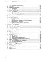
Contains Chapter 1 2 3 4 Description A description of the hardware used on the Desktop Board D915PLWD A map of the resources of the Desktop Board The features supported by the BIOS Setup program A description of the BIOS error messages, beep codes, and POST codes Typographical Conventions This - Intel D915PLWD | Product Specification - Page 4
Intel Desktop Board D915PLWD Technical Product Specification Other Common Notation # (NxnX) GB GB of a component, N indicates component type, xn are the relative coordinates of its location on the board, and X is the instance of the particular part at that general location. For example, J5J1 is - Intel D915PLWD | Product Specification - Page 5
1.1 Overview...10 1.1.1 Feature Summary 10 1.1.2 Board Layout 12 1.1.3 Block Diagram 14 1.2 Online Support ...15 1.3 Processor...15 1.4 System Memory ...16 1.4.1 Memory Configurations 17 1.5 Intel® 915PL Chipset 20 1.5.1 USB ...20 1.5.2 IDE Support 20 1.5.3 Real-Time Clock, CMOS SRAM - Intel D915PLWD | Product Specification - Page 6
Markings (Board Level 64 3 Overview of BIOS Features 3.1 Introduction ...65 3.2 BIOS Flash Memory Organization 66 3.3 Resource Configuration 66 3.3.1 PCI Autoconfiguration 66 3.3.2 PCI IDE Support 66 3.4 System Management BIOS (SMBIOS 67 3.5 Legacy USB Support...67 3.6 BIOS Updates ...68 - Intel D915PLWD | Product Specification - Page 7
19. Processor Heatsink for Omni-directional Airflow 57 20. Localized High Temperature Zones 58 Tables 1. Feature Summary ...10 2. Board Components Shown in Figure 1 13 3. Supported System Bus Frequency and Memory Speed Combinations 16 4. Supported Memory Configurations 16 5. LAN Connector LED - Intel D915PLWD | Product Specification - Page 8
Intel Desktop Board D915PLWD Technical Product Specification 26. States for a One-Color Power LED 50 27. States for a Two-Color Power LED 50 28. BIOS Setup Configuration Jumper Settings 52 29. DC Loading Characteristics 55 30. Fan Connector Current Capability 56 31. Thermal Considerations for - Intel D915PLWD | Product Specification - Page 9
What This Chapter Contains 1.1 Overview ...10 1.2 Online Support ...15 1.3 Processor ...15 1.4 System Memory ...16 1.5 Intel® 915PL Chipset...20 1.6 PCI Express Connectors 22 1.7 Legacy I/O Controller 23 1.8 Audio Subsystem ...24 1.9 LAN Subsystem ...26 1.10 Hardware Management Subsystem 27 1.11 - Intel D915PLWD | Product Specification - Page 10
Intel Desktop Board D915PLWD Technical Product Specification 1.1 Overview 1.1.1 Feature Summary Table 1 summarizes the major features of the board. Table 1. Feature Summary Form Factor Processor Memory ATX (12.00 inches by 9.60 inches [304.80 millimeters by 243.84 millimeters]) Support for an - Intel D915PLWD | Product Specification - Page 11
connector Instantly Available PC Technology • Support for PCI Local Bus Specification Revision 2.2 • Support for PCI Express Revision 1.0a • Suspend to RAM support • Wake on PCI, RS-232 For information about Available configurations for the Desktop Board D915PLWD Refer to Section 1.2, page 15 11 - Intel D915PLWD | Product Specification - Page 12
Intel Desktop Board D915PLWD Technical Product Specification 1.1.2 Board Layout Figure 1 shows the location of the major components. A B C D EF G H I J K DD CC L M N BB O Z XV AA Y W U T S R QP Figure 1. Board Components Table 2 lists the components identified in Figure 1. OM17971 - Intel D915PLWD | Product Specification - Page 13
-in card connector H Rear chassis fan connector I Back panel connectors J +12V power connector (ATX12V) K LGA775 processor socket L Processor fan connector M Intel 82915PL MCH N DIMM Channel A socket O DIMM Channel B socket P Legacy I/O controller Q Power connector R Diskette - Intel D915PLWD | Product Specification - Page 14
board. PCI Express x1 Interface PCI Express x1 Slot 1 PCI Express x1 Slot 2 USB Back Panel/ Front Panel USB Ports Parallel ATA IDE Connector Parallel ATA IDE Interface LGA775 Processor Socket System Bus (800/533 MHz) PCI Express x16 Interface PCI Express x16 Connector Intel 82915PL Memory - Intel D915PLWD | Product Specification - Page 15
for the Desktop Board D915PLWD Processor data sheets ICH6 addressing Custom splash screens Audio software and utilities LAN software and drivers Visit this World Wide Web site: http://www.intel.com/design/motherbd http://support.intel.com/support/motherboards/desktop http://developer.intel.com - Intel D915PLWD | Product Specification - Page 16
Intel Desktop Board D915PLWD Technical Product Specification 1.4 System Memory The board has two DIMM sockets and support the following memory features: • 2.5 V (only) DDR SDRAM DIMMs with gold-plated contacts • Unbuffered, single-sided or double-sided DIMMs with the following restriction: Double- - Intel D915PLWD | Product Specification - Page 17
Product Description 1.4.1 Memory Configurations The Intel 82915PL MCH supports two types of memory organization: • Dual channel (Interleaved) mode. This mode offers the highest throughput for real world applications. Dual channel mode is enabled when the installed memory capacities of both DIMM - Intel D915PLWD | Product Specification - Page 18
Intel Desktop Board D915PLWD Technical Product Specification 1.4.1.1 Dual Channel (Interleaved) Mode Configuration Figure 4 shows a dual channel configuration using two DIMMs. In this example, the DIMM sockets are populated with - Intel D915PLWD | Product Specification - Page 19
Product Description 1.4.1.2 Single Channel (Asymmetric) Mode Configurations NOTE Dual channel (Interleaved) mode configurations provide the highest memory throughput. Figure 5 shows a single channel configuration using one DIMM. In this example, only Channel A is populated. Channel B is not - Intel D915PLWD | Product Specification - Page 20
nonvolatile storage of the BIOS. For information about The Intel 915PL chipset Resources used by the chipset Refer to http://developer.intel.com/ Chapter 2 1.5.1 USB The board supports up to eight USB 2.0 ports, supports UHCI and EHCI, and uses UHCI- and EHCI-compatible drivers. The ICH6 provides - Intel D915PLWD | Product Specification - Page 21
supports the following modes: • Programmed I/O (PIO): processor controls data transfer. • 8237-style DMA: DMA offloads the processor, supporting bus supporting host and target throttling and transfer rates of up to 66 MB/sec. ATA-66 protocol is similar to Ultra DMA and is device driver compatible. • - Intel D915PLWD | Product Specification - Page 22
Intel Desktop Board D915PLWD Technical Product Specification 1.5.3 Real-Time Clock, CMOS SRAM, and Battery A coin-cell battery (CR2032) powers the real-time clock and CMOS memory. When the computer is not plugged into a wall socket, the battery has an estimated life of three years. When the computer - Intel D915PLWD | Product Specification - Page 23
(ECP) and Enhanced Parallel Port (EPP) support • Serial IRQ interface compatible with serialized IRQ support for PCI Conventional bus systems • PS/2-style Diskette Drive Controller The legacy I/O controller supports one diskette drive. Use the BIOS Setup program to configure the diskette drive - Intel D915PLWD | Product Specification - Page 24
Intel Desktop Board D915PLWD Technical Product Specification 1.8 Audio Subsystem The board supports the Intel High Definition audio subsystem based on the Realtek ALC860VU codec. The audio subsystem supports the following features: • Advanced jack sense (front and rear panel) that enables the audio - Intel D915PLWD | Product Specification - Page 25
includes the following: • Intel 82801FB I/O Controller Hub (ICH6) • Realtek ALC860VU audio codec • Microphone input that supports a single dynamic, condenser, or electret microphone The front and back audio connectors are configurable through the audio device drivers. The available configurable - Intel D915PLWD | Product Specification - Page 26
Desktop Board D915PLWD Technical Product Specification 1.9 LAN Subsystem The LAN subsystem consists of the following: • Physical layer interface device Intel 82562GZ PLC for 10/100 Mbits/sec Ethernet LAN connectivity. • RJ-45 LAN connector with integrated status LEDs Additional features of the LAN - Intel D915PLWD | Product Specification - Page 27
LAN Subsystem Software LAN software and drivers are available from Intel's World Wide Web site. For information about Refer to Obtaining LAN software and drivers Section 1.2, page 15 1.10 Hardware Management Subsystem The hardware management features enable the Desktop Boards to be compatible - Intel D915PLWD | Product Specification - Page 28
Intel Desktop Board D915PLWD Technical Product Specification 1.10.2 Thermal Monitoring Figure 10 shows the location of the sensors and fan connectors. 3 1 A CB 4 1 D 1 3 Item A B C D E F F E OM17977 Description Remote ambient temperature sensor Thermal diode, located on processor die - Intel D915PLWD | Product Specification - Page 29
an operating system that provides full ACPI support. ACPI features include: • Plug and Play (including bus and device enumeration) • Power management control of individual devices, add-in boards (some add-in boards may require an ACPI-aware driver), video displays, and hard disk drives • Methods for - Intel D915PLWD | Product Specification - Page 30
Intel Desktop Board D915PLWD Technical Product Specification Table 6 lists the system states based system as a whole into a low-power state. Table 7 lists the power states supported by the board along with the associated system power targets. See the ACPI specification for a complete description - Intel D915PLWD | Product Specification - Page 31
Full power > 30 W G1 - sleeping state S1 - Processor stopped C1 - stop grant D1, D2, D3 - device Service can be performed safely. Notes: 1. Total system power is dependent on the system configuration, including add-in boards not apply to the S3 (Suspend to RAM) or S4 (Suspend to disk) states. - Intel D915PLWD | Product Specification - Page 32
Intel Desktop Board D915PLWD Technical Product Specification 1.11.1.3 Wake-up Devices and Events Table 8 lists the devices or specific events that can wake the computer from specific states. Table 8. Wake-up Devices and Events These devices/events can wake up the computer... LAN Modem (back panel - Intel D915PLWD | Product Specification - Page 33
and sensors for thermal monitoring The signal names of the processor fan connector The signal names of the chassis fan connectors Refer to Figure 10, page 28 Table 20, page 46 Table 21, page 46 1.11.2.3 LAN Wake Capabilities CAUTION For LAN wake capabilities, the +5 V standby line for the power - Intel D915PLWD | Product Specification - Page 34
Intel Desktop Board D915PLWD Technical Product Specification Magic Packet* frame, the LAN subsystem asserts a wake-up signal that powers up the computer. Depending on the LAN implementation, the board supports LAN technology enables the board to enter the ACPI S3 (Suspend-to-RAM) sleep-state. While - Intel D915PLWD | Product Specification - Page 35
S3, S4, or S5 state (with Wake on PME enabled in BIOS). 1.11.2.9 WAKE# Signal Wake-up Support When the WAKE# signal on the PCI Express bus is asserted, installing or removing any devices connected to the board. Failure to do so could damage the board and any attached devices. CR3J1 OM17978 Figure 11 - Intel D915PLWD | Product Specification - Page 36
Intel Desktop Board D915PLWD Technical Product Specification 36 - Intel D915PLWD | Product Specification - Page 37
127 KB 512 KB Description Extended memory Runtime BIOS Reserved Potential available high DOS memory (open to the PCI Conventional bus). Dependent on video adapter used. Video memory and BIOS Extended BIOS data (movable by memory manager software) Extended conventional memory Conventional memory 37 - Intel D915PLWD | Product Specification - Page 38
Intel Desktop Board D915PLWD Technical Product Specification 2.2 DMA Channels Table 10. DMA Channels DMA Channel Number 0 1 2 3 4 5 6 7 Data Width 8 or 16 bits 8 or 16 bits 8 or 16 bits 8 or 16 - Intel D915PLWD | Product Specification - Page 39
8 bytes 4 bytes 7 bits 8 bytes 8 bytes 6 bytes 1 byte 8 bytes 2 bytes 8 bytes 4 bytes 1 byte 4 bytes 8 bytes 8 bytes Description Used by the Desktop Board D915PLWD. Refer to the ICH6 data sheet for dynamic addressing information. Secondary Parallel ATA IDE channel command block Primary Parallel ATA - Intel D915PLWD | Product Specification - Page 40
Intel Desktop Board D915PLWD 00 00 00 00 00 Description Memory controller of Intel 82915PL component PCI Express x16 graphics port (Note 1) Intel High Definition Audio Controller PCI Express Conventional bus connector 4 Intel 82562GZ 10/100 Mbits/sec LAN PLC PCI Express video controller (if present) - Intel D915PLWD | Product Specification - Page 41
in Windows 98 SE and Windows ME and uses the first 16 interrupts. The APIC is supported in Windows 2000 and Windows XP and supports a total of 24 interrupts. Table 13. Interrupts IRQ NMI 0 1 2 3 4 5 6 7 8 9 10 11 12 13 14 15 16 (Note 2) 17 (Note 2) 18 (Note 2) 19 (Note 2) 20 (Note 2) - Intel D915PLWD | Product Specification - Page 42
Intel Desktop Board D915PLWD Technical Product Specification 2.6 PCI Conventional* Interrupt Routing of how the PIRQ signals are routed. Table 14. PCI Interrupt Routing Map PCI Interrupt Source ICH6 LAN PCI bus connector 1 PCI bus connector 2 PCI bus connector 3 PCI bus connector 4 PIRQA PIRQB - Intel D915PLWD | Product Specification - Page 43
cable, and the external devices themselves. This section describes the board's connectors. The connectors can be divided into these groups: • D (Lime Green) Mic in/Retasking Port B (Pink) USB ports (four) LAN NOTE The back panel audio line out connector is designed to power headphones or amplified - Intel D915PLWD | Product Specification - Page 44
Intel Desktop Board D915PLWD Technical Product Specification 2.7.2 Component-side Connectors Figure 13 shows the locations of the component-side connectors. A B C D EF G H I J 12 9 10 3 1 3 4 3 1 12 10 11 12 10 9 1 11 2 1 1 3 4 1 X W 1 2 1 - Intel D915PLWD | Product Specification - Page 45
card connector 1 H PCI Express x16 bus add-in card connector I Rear chassis fan connector J +12V power connector (ATX12V) K Processor fan connector L Power connector M Diskette drive connector N Parallel ATA IDE connector O Chassis intrusion connector P Front chassis fan connector - Intel D915PLWD | Product Specification - Page 46
Intel Desktop Board D915PLWD Technical Product Specification Table 17. Front Panel Audio Connector Pin Signal Name Pin 1 Port E [Port 1] 2 TXP 3 TXN 4 Ground 5 RXN 6 RXP 7 Ground Table 20. Processor Fan Connector Pin Signal Name 1 Ground 2 +12 V 3 FAN_TACH 4 FAN_CONTROL - Intel D915PLWD | Product Specification - Page 47
x 12 connector. This connector is compatible with 2 x 10 connectors previously used on Intel desktop boards. The board supports the use of ATX12V power supplies power directly to the processor voltage regulator and must always be used. Failure to do so will prevent the board from booting. Table 22 - Intel D915PLWD | Product Specification - Page 48
Intel Desktop Board D915PLWD Technical Product Specification 2.7.2.2 Add-in Card Connectors The board has the following add-in card connectors: • PCI Express x16: one connector supporting simultaneous transfer speeds up to 8 GBytes/sec. • PCI Express x1: two PCI Express x1 connectors. The x1 - Intel D915PLWD | Product Specification - Page 49
Technical Reference 2.7.2.4 Front Panel Connector This section describes the functions of the front panel connector. Table 25 lists the signal names of the front panel connector. Figure 14 is a connection diagram for the front panel connector. Table 25. Front Panel Connector Pin Signal In/Out - Intel D915PLWD | Product Specification - Page 50
Intel Desktop Board D915PLWD Technical Product Specification 2.7.2.4.2 Reset Switch Connector [Purple] Pins 5 and 7 [Purple] can be connected to a momentary single pole, single throw (SPST) type switch that is normally open. When the switch is closed, the board resets and runs the POST. 2.7.2.4.3 - Intel D915PLWD | Product Specification - Page 51
Technical Reference 2.7.3 Front Panel USB Connectors Figure 15 is a connection diagram for the front panel USB connectors. # INTEGRATOR'S NOTES • The +5 V DC power on the USB connector is fused. • Pins 1, 3, 5, and 7 comprise one USB port. • Pins 2, 4, 6, and 8 comprise one USB port. • Use only a - Intel D915PLWD | Product Specification - Page 52
Intel Desktop Board D915PLWD Technical Product Specification 2.8 Jumper Block CAUTION Do not move the jumper with the power on. Always turn off the power and unplug the power cord from the computer before changing a jumper setting. Otherwise, the board could be damaged. Figure 16 shows the location - Intel D915PLWD | Product Specification - Page 53
Technical Reference 2.9 Mechanical Considerations 2.9.1 Form Factor The board is designed to fit into an ATX-form-factor chassis. Figure 17 illustrates the mechanical form factor of the board. Dimensions are given in inches [millimeters]. The outer dimensions are 12.00 inches by 9.60 inches [304. - Intel D915PLWD | Product Specification - Page 54
Intel Desktop Board D915PLWD Technical Product Specification 2.9.2 I/O Shield The back panel I/O shield for the board must meet specific dimension and material requirements. Systems based on this board shield compliant with the ATX chassis specification 2.03 is available from Intel. 1.55 REF [0.061 - Intel D915PLWD | Product Specification - Page 55
draw per USB port. These calculations are not based on specific processor values or memory configurations but are based on the minimum and maximum current draw possible from the board's power delivery subsystems to the processor, memory, and USB ports. Use the datasheets for add-in cards, such - Intel D915PLWD | Product Specification - Page 56
Intel Desktop Board D915PLWD Technical Product Specification 2.10.3 Fan Connector Current Capability CAUTION The processor fan must be connected to the processor fan connector, not to a chassis fan connector. Connecting the processor wake devices supported and manufacturing of the ATX form factor - Intel D915PLWD | Product Specification - Page 57
in reduced performance of both the processor and/or voltage regulator or, in some instances, damage to the board. For a list of chassis that have been tested with Intel desktop boards please refer to the following website: http://developer.intel.com/design/motherbd/cooling.htm All responsibility - Intel D915PLWD | Product Specification - Page 58
Intel Desktop Board D915PLWD Technical Product Specification CAUTION Ensure that proper airflow is maintained in the processor voltage regulator circuit. Failure to do so may result in damage to the voltage regulator circuit. The processor voltage regulator area (item A in Figure 20) can reach a - Intel D915PLWD | Product Specification - Page 59
board. Table 31. Thermal Considerations for Components Component Intel Pentium 4 processor Intel 82915PL MCH Intel 82801FB ICH6 Maximum Case Temperature For processor case temperature, see processor datasheets and processor specification updates MTBF for the D915PLWD board is 126,666 hours. 59 - Intel D915PLWD | Product Specification - Page 60
Intel Desktop Board D915PLWD Technical Product Specification 2.13 Environmental Table 32 lists the environmental specifications for the board. Table 32. Environmental Specifications Parameter Temperature Non-Operating Operating Shock Unpackaged Packaged Vibration Unpackaged Packaged - Intel D915PLWD | Product Specification - Page 61
Safety - Part 1: General Requirements (International) 2.14.2 EMC Regulations Table 34 lists the EMC regulations the Desktop Board D915PLWD complies with when correctly installed in a compatible host system. Table 34. EMC Regulations Regulation FCC (Class B) ICES-003 (Class B) EN55022: 1998 (Class - Intel D915PLWD | Product Specification - Page 62
Intel Desktop Board D915PLWD Technical Product Specification 2.14.2.1 FCC Compliance Statement (USA) Product Type: D915PLWD Desktop Board This device complies and, if not installed and used in accordance with the instructions, may cause harmful interference to radio communications. However, there - Intel D915PLWD | Product Specification - Page 63
be regulated upon disposal: lead solder on the printed wiring board assembly. 2.14.4.2 Recycling Considerations Intel encourages its customers to recycle its products and their components (e.g., batteries, circuit boards, plastic enclosures, etc.) whenever possible. In the U.S., a list of recyclers - Intel D915PLWD | Product Specification - Page 64
US/Canada Recognized Component mark. Includes adjacent UL file number for Intel Desktop Boards: E210882 (component side). FCC Declaration of Conformity logo mark for Class B equipment; includes Intel name and D915PLWD model designation (component side). Marking CE mark. Declares compliance to - Intel D915PLWD | Product Specification - Page 65
Resource Configuration 66 3.4 System Management BIOS (SMBIOS 67 3.5 Legacy USB Support...67 3.6 BIOS Updates ...68 3.7 Boot Options ...69 3.8 Adjusting Boot Speed 70 3.9 BIOS Security Features 71 3.1 Introduction The board uses an Intel® BIOS that is stored in the Firmware Hub (FWH) and can be - Intel D915PLWD | Product Specification - Page 66
Intel Desktop Board D915PLWD Technical Product Specification Table 36 lists the BIOS Setup program menu features. Table 36. BIOS Setup Program Menu Bar Maintenance Main Advanced Security Clears passwords and displays processor information Displays processor and memory configuration Configures - Intel D915PLWD | Product Specification - Page 67
override the autoconfiguration options by specifying manual configuration in the BIOS Setup program. To use ATA-66/100 features the following items are required: • An ATA-66/100 peripheral device • An ATA-66/100 compatible cable • ATA-66/100 operating system device drivers NOTE Do not connect an ATA - Intel D915PLWD | Product Specification - Page 68
Intel Desktop Board D915PLWD Technical Product Specification 5. The operating system loads. While the operating system is loading, USB keyboards and mice are recognized and may be used to configure the operating system. 6. After the operating system loads the USB drivers, all legacy and non-legacy - Intel D915PLWD | Product Specification - Page 69
supported in compliance to the El Torito bootable CD-ROM format specification. Under the Boot menu in the BIOS from the onboard LAN or a network add-in BIOS has been designed so that after passing the POST, the operating system loader is invoked even if the following devices are not present: • Video - Intel D915PLWD | Product Specification - Page 70
Intel Desktop Board D915PLWD Technical Product Specification 3.8 Adjusting Boot Speed These factors affect system boot speed: • Selecting and configuring peripherals properly • Optimized BIOS images and changing video modes. In the Peripheral Configuration submenu, disable the LAN device if it - Intel D915PLWD | Product Specification - Page 71
Setup program. This is the user mode. • If only the supervisor password is set, pressing the key at the password prompt of the BIOS Setup program allows the user restricted access to Setup. • If both the supervisor and user passwords are set, users can enter either the supervisor password - Intel D915PLWD | Product Specification - Page 72
Intel Desktop Board D915PLWD Technical Product Specification 72 - Intel D915PLWD | Product Specification - Page 73
messages and provides a brief description of each. Table 40. BIOS Error Messages Error Message GA20 Error Pri Master HDD Error Pri Slave HDD Error Pri Master Drive - ATAPI Incompatible Pri Slave Drive - ATAPI Incompatible A: Drive Error Cache Memory Bad CMOS Battery Low CMOS Display Type Wrong CMOS - Intel D915PLWD | Product Specification - Page 74
Intel Desktop Board D915PLWD Technical Product Specification Table 40. BIOS Error Messages (continued) Error Message Explanation Update OK! NVRAM was invalid and has been updated. Updated Failed NVRAM was invalid but was unable to be updated. Keyboard Error Error in the keyboard connection. - Intel D915PLWD | Product Specification - Page 75
go to check point D7 for giving control to main BIOS. D7 Find Main BIOS module in ROM image. D8 Uncompress the main BIOS module. D9 Copy main BIOS image to F000 shadow RAM and give control to main BIOS in F000 shadow RAM. Table 42. Boot Block Recovery Code Checkpoints Code Description of - Intel D915PLWD | Product Specification - Page 76
Intel Desktop Board D915PLWD Technical Product Specification Table 43. Runtime Code Uncompressed in F000 Shadow RAM Code 03 05 06 Disabled. To check soft reset/power-on. BIOS stack set. Going to disable cache if any. POST code to be uncompressed. CPU init and CPU data area init to be done. CMOS - Intel D915PLWD | Product Specification - Page 77
to display the first 64k memory size. Memory size display started. This will be updated during memory test. Going for sequential and random memory test. Memory testing/initialization below 1M complete. Going to adjust displayed memory size for relocation/shadow. Memory size display adjusted due to - Intel D915PLWD | Product Specification - Page 78
Intel Desktop Board D915PLWD Technical Product Specification Table 43. Runtime Code Uncompressed in F000 Shadow RAM over. To check for memory size mismatch with CMOS. Memory size check done. To PS/2 Mouse check and extended BIOS data area allocation to be support (if present). Put CGA INT10 - Intel D915PLWD | Product Specification - Page 79
Codes Table 43. Runtime Code Uncompressed in F000 Shadow RAM (continued) Code AE B1 00 Description of POST Operation execution. In these WORD checkpoints, the low byte of the checkpoint is the system BIOS checkpoint from which the control is passed to the different bus routines. The high byte - Intel D915PLWD | Product Specification - Page 80
Intel Desktop Board D915PLWD Technical Product Specification Table 46 describes the lower nibble of , the BIOS issues one short beep before passing control to the operating system. Table 47. Beep Codes Beep 1 3 6 7 8 Description CPU error Memory error System failure System failure Video error 80
-
 1
1 -
 2
2 -
 3
3 -
 4
4 -
 5
5 -
 6
6 -
 7
7 -
8
-
9
-
10
-
11
-
12
-
13
-
14
-
15
-
16
-
17
-
18
-
19
-
20
-
21
-
22
-
23
-
24
-
25
-
26
-
27
-
28
-
29
-
30
-
31
-
32
-
33
-
34
-
35
-
36
-
37
-
38
-
39
-
40
-
41
-
42
-
43
-
44
-
45
-
46
-
47
-
48
-
49
-
50
-
51
-
52
-
53
-
54
-
55
-
56
-
57
-
58
-
59
-
60
-
61
-
62
-
63
-
64
-
65
-
66
-
67
-
68
-
69
-
70
-
71
-
72
-
73
-
74
-
75
-
76
-
77
-
78
-
79
-
80
 |
 |

June 2005
Order Number:
D23930-001US
The Intel
®
Desktop Board D915PLWD may contain design defects or errors known as errata that may cause the product to deviate from published specifications.
Current
characterized errata are documented in the Intel Desktop Board D915PLWD Specification Update.
Intel
®
Desktop Board
D915PLWD
Technical Product Specification