Intel D945GCZ Product Guide
Intel D945GCZ - Desktop Board Motherboard Manual
 |
UPC - 735858174770
View all Intel D945GCZ manuals
Add to My Manuals
Save this manual to your list of manuals |
Intel D945GCZ manual content summary:
- Intel D945GCZ | Product Guide - Page 1
Intel® Desktop Board D945GCZ Product Guide Order Number: D10476-004 - Intel D945GCZ | Product Guide - Page 2
-003 -004 Revision History First release of the Intel® Desktop Board D945GCZ Product Guide Second release of the Intel® Desktop Board D945GCZ Product Guide Third release of the Intel® Desktop Board D945GCZ Product Guide Added operating system support Date March 2005 August 2005 April 2006 February - Intel D945GCZ | Product Guide - Page 3
: instructions on how to update the BIOS 4 Configuring for RAID (Intel® Matrix Storage Technology) Requires Microsoft Windows* XP or 2000 and SATA Hard Drive(s): information about configuring the system for RAID A Error Messages and Indicators: information about BIOS error messages and beep codes - Intel D945GCZ | Product Guide - Page 4
Contents • Intel Desktop Board D945GCZ • I/O shield • One ATA-66/100 cable • Two locking Serial ATA cables • One diskette drive cable • One VGA port cover • Quick Reference poster • Configuration and battery caution statement label • Intel® Express Installer driver CD-ROM • Intel Express Installer - Intel D945GCZ | Product Guide - Page 5
19 Serial ATA...19 Expandability...19 BIOS ...20 Serial ATA and IDE Auto Configuration 20 PCI and PCI Express Auto Configuration 20 Security Passwords ...20 Chassis Intrusion...20 Power Management Features 21 ACPI...21 Power Connectors...21 Fan Connectors...21 Fan Speed Control (Intel® Precision - Intel D945GCZ | Product Guide - Page 6
Windows* XP or 2000 and SATA Hard Drive(s) Configuring the BIOS for Intel Matrix Storage Technology 59 Creating Your RAID Set ...59 Loading the Intel Matrix Storage Technology RAID Drivers and Software 60 Setting Up a "RAID Ready" System 60 A Error Messages and Indicators BIOS Beep Codes - Intel D945GCZ | Product Guide - Page 7
a Serial ATA Cable 40 20. Internal Headers ...41 21. Back Panel Audio Connectors for Flexible 6-Channel Audio System 44 22. Location of Fan Headers 45 23. Connecting Power Supply Cables 46 24. Location of Other Connectors on Desktop Board D945GCZ 47 25. Location of the BIOS Configuration - Intel D945GCZ | Product Guide - Page 8
Board D945GCZ Components 13 4. Power Supply Requirements 14 5. Desktop Board D945GCZ Memory Configurations 15 6. RJ-45 10/100 Ethernet LAN Connector LEDs 18 7. RJ-45 10/100/1000 Gigabit Ethernet LAN Connector LEDs 18 8. Front Panel Audio Header Signal Names for Intel High Definition Audio - Intel D945GCZ | Product Guide - Page 9
of Intel® Desktop Board D945GCZ. Table 1 summarizes the major features of the desktop board. Table 1. Feature Summary Form Factors Processor Main Memory Chipset Graphics Audio Expansion Capabilities Peripheral Interfaces MicroBTX (10.4-inches x 10.5-inches) Support for an Intel® processor - Intel D945GCZ | Product Guide - Page 10
Cooling Technology fan speed control • Voltage sensing to detect out of range values Related Links: For more information about desktop board D945GCZ, including the Technical Product Specification (TPS), BIOS updates, and device drivers, go to: http://support.intel.com/support/motherboards/desktop - Intel D945GCZ | Product Guide - Page 11
The desktop board supports the following operating systems: • Microsoft Vista* Home Premium • Microsoft Vista Home Premium 64-bit edition • Microsoft Vista Home Basic • Microsoft Vista Home Basic 64-bit edition • Microsoft Windows* XP Media Center Edition 2005 • Microsoft Windows XP Professional - Intel D945GCZ | Product Guide - Page 12
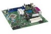
Figure 1 shows the approximate location of the major components on desktop board D945GCZ. IEEE 1394a (Optional) (Optional) Line In Optical Line Out (Toslink) (Optional) A S R Q BC DE F G R Intel 82801 (ICH7) H Channel A DIMM 0 Channel A DIMM 1 Channel B DIMM 0 Channel B DIMM 1 IntelR - Intel D945GCZ | Product Guide - Page 13
, fan speed control) IDE connector Chassis intrusion header Related Links: Go to the following links for more information about: • Desktop board D945GCZ • Supported processors • Audio software and utilities • LAN software and drivers http://www.intel.com/design/motherbd http://support.intel.com - Intel D945GCZ | Product Guide - Page 14
board D945GCZ is located on the web at: http://support.intel.com/support/motherboards/desktop/ Related Links: Go to the following links or pages for more information about: • Instructions on installing or upgrading the processor, page 30 in Chapter 2 • The location of the two power connectors - Intel D945GCZ | Product Guide - Page 15
screen at power up. The BIOS will attempt to configure the memory controller for normal operation. The desktop board supports dual or single channel memory configurations defined in Table 5. Table 5. Desktop Board D945GCZ Memory Configurations Memory Speed FSB Frequency (MHz) Memory Speed (MHz - Intel D945GCZ | Product Guide - Page 16
D945GCZ Product Guide Intel® 945G Express Chipset The Intel 945G Express Chipset consists of the following devices: • Intel 82945G Graphics and Memory Controller Hub (GMCH) with Digital Media Interface • Intel 82801GB I/O Controller Hub (ICH7) or Intel 82801GR I/O Controller Hub (ICH7R) supporting - Intel D945GCZ | Product Guide - Page 17
support.intel.com/support/motherboards/desktop/ • Installing the front panel audio solution, page 42 in Chapter 2 • The location of audio connectors, Figure 21 on page 44 Input/Output (I/O) Controller The super I/O controller features the following: • Low pin count (LPC) interface • One serial port - Intel D945GCZ | Product Guide - Page 18
Intel Desktop Board D945GCZ Product Guide RJ-45 LAN Connector LEDs Two LEDs are built into the RJ-45 LAN port located on the back panel (see Figure 2). OM17386 Figure 2. LAN Port LED Locations Table 6 describes the LED states when the board is powered up and the 10/100 Ethernet LAN subsystem is - Intel D945GCZ | Product Guide - Page 19
are backward compatible with USB 1.1 devices. USB 1.1 devices will function normally at USB 1.1 speeds. USB 2.0 support requires both an operating system and drivers that fully support USB 2.0 transfer rates. Disabling Hi-Speed USB in the BIOS reverts all USB 2.0 ports to USB 1.1 operation. This may - Intel D945GCZ | Product Guide - Page 20
Intel Desktop Board D945GCZ Product Guide BIOS The BIOS provides the Power-On Self-Test (POST), the BIOS Setup program, the PCI/PCI Express and IDE auto-configuration utilities, and the video BIOS. The BIOS is stored in the Firmware Hub. The BIOS can be updated by following the instructions on page - Intel D945GCZ | Product Guide - Page 21
desktop board BIOS. Disabling the processor fan speed control will result in the fan operating at full speed if it is not a self controlled fan. It is recommended that processor fan speed control remain enabled (default BIOS setting) when using the processor fan heat-sink included with Intel® boxed - Intel D945GCZ | Product Guide - Page 22
If the standby current necessary to support multiple wake events from the PCI and/or USB buses exceeds power supply capacity, the desktop board may lose register settings stored in memory. Instantly Available PC technology enables the board to enter the ACPI S3 (Suspend-to-RAM) sleep state. While in - Intel D945GCZ | Product Guide - Page 23
on the desktop board. The speaker provides audible error code (beep code) information during the Power-On Self-Test (POST). Battery A battery on the desktop board keeps the values in CMOS RAM and the clock current when the computer is turned off. Go to page 50 for instructions on how to replace - Intel D945GCZ | Product Guide - Page 24
Intel Desktop Board D945GCZ Product Guide 24 - Intel D945GCZ | Product Guide - Page 25
the desktop board • Install and remove a processor and memory • Install and remove a PCI Express x16 card • Connect the IDE and Serial ATA cables • Connect internal headers • Set up flexible 6-channel audio with jack re-tasking • Connect fan and power cables • Locate other connectors • Set the BIOS - Intel D945GCZ | Product Guide - Page 26
components (like processors, voltage regulators, and heat sinks) • Damage to wires that could cause a short circuit Observe all warnings and cautions that instruct you to refer computer servicing to qualified technical personnel. Installation Instructions NOTE Follow these guidelines to meet safety - Intel D945GCZ | Product Guide - Page 27
the computer is less than the output current rating of each of the power supplies output circuits. Place Battery Marking CAUTION Risk of explosion if the regulations. There is insufficient space on this desktop board to provide instructions for replacing and disposing of the Lithium ion coin - Intel D945GCZ | Product Guide - Page 28
Intel Desktop Board D945GCZ Product Guide Installing the I/O Shield The desktop board comes with an I/O shield. When installed correct airflow within the chassis. Install the I/O shield before installing the desktop board in the chassis. Place the shield inside the chassis as shown in Figure - Intel D945GCZ | Product Guide - Page 29
power before you open the computer can result in personal injury or equipment damage. Refer to your chassis manual for instructions on installing and removing the desktop board. Figure 5 shows the location of the seven mounting screw holes for desktop board D945GCZ. OM17636 Figure 5. Desktop Board - Intel D945GCZ | Product Guide - Page 30
Intel Desktop Board D945GCZ Product Guide Installing and Removing a Processor Instructions on how to install the processor to the desktop board are given below. Installing a Processor CAUTION Before installing or removing the processor, make sure the AC power has been removed by unplugging the power - Intel D945GCZ | Product Guide - Page 31
Installing and Replacing Desktop Board Components 4. Remove the plastic protective socket cover from the load plate (see Figure 8, E). Do not discard the protective socket cover. Always replace the socket cover - Intel D945GCZ | Product Guide - Page 32
Intel Desktop Board D945GCZ Product Guide 6. Hold the processor with your thumb and index fingers oriented as shown in Figure 10. Make sure fingers align to the socket cutouts (see Figure - Intel D945GCZ | Product Guide - Page 33
Installing the Processor Fan Heat Sink Desktop board D945GCZ has an integrated processor fan heat sink retention mechanism (RM). For instructions on how to attach the processor fan heat sink to the integrated processor fan heat sink RM, refer to the boxed processor manual or the Intel World Wide Web - Intel D945GCZ | Product Guide - Page 34
Intel Desktop Board D945GCZ Product Guide Installing and Removing Memory NOTE To be fully compliant with all applicable Intel SDRAM memory specifications, the boards require DIMMs that support the Serial Presence Detect (SPD) data structure. You can access the PC Serial Presence Detect - Intel D945GCZ | Product Guide - Page 35
Replacing Desktop Board Components Three DIMMs Install a matched pair of DIMMs equal in speed and size in DIMM 0 (blue) and DIMM 1 (black) of channel A. Install a DIMM equal in speed and total Example 3 DIMM 0 DIMM 1 DIMM 0 DIMM 1 NOTE All other memory configurations will result in single channel - Intel D945GCZ | Product Guide - Page 36
B DIMM 1 Intel Desktop Board D945GCZ Product Guide Installing DIMMs To install a DIMM, follow these steps: 1. Observe the precautions in "Before You Begin" on page 25. 2. Turn off all peripheral devices connected to the computer. Turn off the computer and disconnect the AC power cord. 3. Remove - Intel D945GCZ | Product Guide - Page 37
Installing and Replacing Desktop Board Components Removing DIMMs To remove a DIMM, follow these steps: 1. Observe the precautions in "Before You Begin" on page 25. 2. Turn off all peripheral devices connected to the computer. Turn off the computer. 3. Remove the AC power cord from the computer. 4. - Intel D945GCZ | Product Guide - Page 38
Intel Desktop Board D945GCZ Product Guide Installing and Removing a PCI Express* x16 Card CAUTION When installing any PCI Express x16 card on the desktop board, ensure that it is fully seated in the PCI Express x16 connector before you power on the system. If the card is not fully seated in the PCI - Intel D945GCZ | Product Guide - Page 39
board. The cable supports the device. For example, do not connect an ATA hard drive as a slave to an ATAPI CD-ROM drive. For correct function of the cable: • Observe the precautions in "Before You Begin" on page 25. • Attach the cable end with the single connector (blue) to the Intel desktop board - Intel D945GCZ | Product Guide - Page 40
Intel Desktop Board D945GCZ Product Guide Connecting a Serial ATA (SATA) Cable The SATA cable (4-conductor) supports the Serial ATA protocol and connects a single drive to the desktop board. For correct cable function: 1. Observe the precaution in "Before You Begin" on page 25. 2. Attach the locking - Intel D945GCZ | Product Guide - Page 41
Installing and Replacing Desktop Board Components Connecting Internal Headers Before Reset No Connection 12 34 56 78 9 Power LED On/Off Item A B C D E F Description Front panel audio Chassis intrusion USB 2.0 (two) IEEE 1394a (two) Alternate power LED Front panel Figure 20. Internal Headers - Intel D945GCZ | Product Guide - Page 42
an AC '97 front panel solution to the front panel audio header on the board. The front panel audio jacks will need to be manually configured for microphone or line out functionality in the Intel® Audio Studio application. Table 9. AC '97 Audio Header Signal Names Pin Signal Name Pin 1 MIC - Intel D945GCZ | Product Guide - Page 43
Front panel green up (330 Ω) to +5 V LED 3 HDA# Out Hard disk active LED 4 HDR_BLNK_YEL Out Front panel yellow LED Reset Switch (Purple) On/Off Switch (Red) 5 GND Ground 6 SWITCH_ON# In Power switch 7 FP_RESET# In Reset switch 8 GND Ground 9 N/C Not connected 10 No pin No pin 43 - Intel D945GCZ | Product Guide - Page 44
Intel Desktop Board D945GCZ Product Guide Setting Up the Flexible 6-Channel Audio with Jack Re-tasking (Optional) NOTE This section applies only to D945GCZ desktop boards with the triple-stack audio connector. After installing the SigmaTel audio driver from the Intel Express Installer driver CD-ROM - Intel D945GCZ | Product Guide - Page 45
and Replacing Desktop Board Components Connecting Fan and Power Cables Connecting Fan Cables Figure 22 shows the location of the fan headers. Connect the processor's fan heat sink cable to the 4-pin processor fan header on the board. Connect chassis fan cables to the 3-pin fan headers. 43 2 1 A 43 - Intel D945GCZ | Product Guide - Page 46
Intel Desktop Board D945GCZ Product Guide Connecting Power Cables CAUTION Failure to use the appropriate power supply and/or not connecting the 12 V (2x2) power connector to the desktop board may result in damage to the board or the system may not function properly. See Table 4 on page 14 for power - Intel D945GCZ | Product Guide - Page 47
-in card, PCI Express 1x, and diskette drive connectors. AB C D Item A B C D OM17644 Description PCI bus add-in card connector 1 PCI bus add-in card connector 2 (SMBus routed) PCI Express x1 connector Diskette drive connector Figure 24. Location of Other Connectors on Desktop Board D945GCZ 47 - Intel D945GCZ | Product Guide - Page 48
Intel Desktop Board D945GCZ Product Guide Setting the BIOS Configuration Jumper Block NOTE Always turn off the power and unplug the power cord from the computer before changing the jumper. Moving the jumper with the power on may result in unreliable computer operation. Figure 25 shows the location - Intel D945GCZ | Product Guide - Page 49
assumes that the board is installed in the computer and the configuration jumper block is set to normal mode. 1. Observe the precautions in "Before You Begin" on page 25. 2. Turn off all peripheral devices connected to the computer. Turn off the computer. Disconnect the computer's power cord from - Intel D945GCZ | Product Guide - Page 50
Intel Desktop Board D945GCZ Product Guide Replacing the Battery A coin-cell battery (CR2032) powers the real-time clock and CMOS memory. When the computer is not plugged into a wall socket, the battery has an estimated life of three years. When the computer is plugged in, the - Intel D945GCZ | Product Guide - Page 51
Installing and Replacing Desktop Board Components AVVERTIMENTO Esiste il pericolo di un esplosione se la pila non viene sostituita in modo corretto. Utilizzare solo pile uguali o di tipo equivalente a quelle - Intel D945GCZ | Product Guide - Page 52
Intel Desktop Board D945GCZ Product Guide AWAS Risiko letupan wujud jika bateri digantikan dengan jenis yang tidak betul. Bateri sepatutnya dikitar semula jika boleh. Pelupusan bateri terpakai mestilah mematuhi peraturan alam - Intel D945GCZ | Product Guide - Page 53
Installing and Replacing Desktop Board Components O 53 - Intel D945GCZ | Product Guide - Page 54
all peripheral devices connected to the computer. Disconnect the computer's power cord from the AC power source (wall outlet or power adapter). 3. Remove the computer cover. 4. Locate the battery on the board (see Figure 26). 5. With a medium flat-bladed screwdriver, gently pry the battery free from - Intel D945GCZ | Product Guide - Page 55
of the Intel® Flash Memory Update Utility and the ease-of use of Windows-based installation wizards. To update the BIOS with the Intel Express BIOS Update utility: 1. Go to the Intel World Wide Web site: http://support.intel.com/support/motherboards/desktop/ 2. Navigate to the D945GCZ page, click - Intel D945GCZ | Product Guide - Page 56
: http://support.intel.com/support/motherboards/desktop Navigate to the D945GCZ page, click "[view] Latest BIOS updates," and select the Iflash BIOS Update utility file. NOTE Review the instructions distributed with the update utility before attempting a BIOS update. The Iflash Memory Update utility - Intel D945GCZ | Product Guide - Page 57
speaker: • Upon applying power, drive A will begin to show activity. In about a minute, two beeps are heard and drive A activity ceases (temporarily) indicating the successful recovery of the BIOS core. Drive A activity will begin again followed by two more beeps indicating the successful recovery - Intel D945GCZ | Product Guide - Page 58
Intel Desktop Board D945GCZ Product Guide 58 - Intel D945GCZ | Product Guide - Page 59
after the Power-On-Self-Test (POST) memory tests begin. 3. Go to Advanced Drive Configuration Configure SATA as; ensure RAID is selected. 4. Then save your settings by pressing . Creating Your RAID Set 1. Upon re-boot, you will see the following Intel Matrix Storage Manager option ROM status - Intel D945GCZ | Product Guide - Page 60
included with your desktop board or after downloading it from the Internet at http://support.intel.com/support/motherboards/desktop/. The Intel Matrix Storage Console software can be used to manage the RAID configuration. Setting Up a "RAID Ready" System The Intel Matrix Storage Technology Console - Intel D945GCZ | Product Guide - Page 61
checksum to zero. Table 14 lists the BIOS codes. Table 14. Beep Codes Beep 3 Siren Description No memory CPU overheat (on reboot) BIOS Error Messages When a recoverable error occurs during the POST, the BIOS displays an error message describing the problem. Table 15 gives an explanation of the - Intel D945GCZ | Product Guide - Page 62
Intel Desktop Board D945GCZ Product Guide 62 - Intel D945GCZ | Product Guide - Page 63
- Safety - Part 1: General Requirements (International) European Union Declaration of Conformity Statement We, Intel Corporation, declare under our sole responsibility that the product Intel® Desktop Board D945GCZ is in conformity with all applicable essential requirements necessary for CE marking - Intel D945GCZ | Product Guide - Page 64
Intel Desktop Board D945GCZ Product Guide Čeština Tento výrobek odpovídá požadavkům evropských směrnic 89/336/EEC a 73/23/EEC. Dansk Dette produkt er i overensstemmelse med det europæiske - Intel D945GCZ | Product Guide - Page 65
scope of covered products, available locations, shipping instructions, terms and conditions, etc. Intel Product Recycling Program 请参考http://www.intel.com/intel/other/ehs/product_ecology/Recycling_Program.htm Deutsch Als Teil von Intels Engagement für den Umweltschutz hat das Unternehmen das - Intel D945GCZ | Product Guide - Page 66
Intel Desktop Board D945GCZ Product Guide Français Dans le cadre de son engagement pour la protection de l'environnement, Intel a mis en œuvre le programme Intel Product Recycling Program (Programme de recyclage des produits Intel) pour permettre aux consommateurs de produits Intel de recycler les - Intel D945GCZ | Product Guide - Page 67
Intel Intel (Product Recycling Program Intel http://www.intel.com/intel/other/ehs/product_ecology/Recycling_Program.htm Türkçe Intel, çevre sorumluluğuna bağımlılığının bir parçası olarak, perakende tüketicilerin Intel geri dönüştürmesini amaçlayan Intel Ürünleri Geri Dönüşüm Programı'nı - Intel D945GCZ | Product Guide - Page 68
Intel Desktop Board D945GCZ Product Guide Lead-Free Desktop Board This desktop board is lead free although certain discrete components used on the board contain a small amount of lead which is necessary for component performance and/or reliability. This desktop board is referred to as "Lead-free - Intel D945GCZ | Product Guide - Page 69
of the Voluntary Control Council for Interference from Information Technology Equipment (VCCI). If this is used near a radio or television receiver in a domestic environment, it may cause radio interference. Install and use the equipment according to the instruction manual. Korean Class B statement - Intel D945GCZ | Product Guide - Page 70
mark. For information about MIC certification, go to http://support.intel.com/support/motherboards/desktop/ Taiwan BSMI (Bureau of Standards, Metrology and Inspections) mark. Includes adjacent Intel company number, D33025. Printed wiring board manufacturer's recognition mark. Consists of a unique UL
-
 1
1 -
 2
2 -
 3
3 -
 4
4 -
 5
5 -
 6
6 -
 7
7 -
8
-
9
-
10
-
11
-
12
-
13
-
14
-
15
-
16
-
17
-
18
-
19
-
20
-
21
-
22
-
23
-
24
-
25
-
26
-
27
-
28
-
29
-
30
-
31
-
32
-
33
-
34
-
35
-
36
-
37
-
38
-
39
-
40
-
41
-
42
-
43
-
44
-
45
-
46
-
47
-
48
-
49
-
50
-
51
-
52
-
53
-
54
-
55
-
56
-
57
-
58
-
59
-
60
-
61
-
62
-
63
-
64
-
65
-
66
-
67
-
68
-
69
-
70
 |
 |

Intel® Desktop Board D945GCZ
Product Guide
Order Number:
D10476-004