Intel DBS1200BTS Product Specification
Intel DBS1200BTS Manual
 |
View all Intel DBS1200BTS manuals
Add to My Manuals
Save this manual to your list of manuals |
Intel DBS1200BTS manual content summary:
- Intel DBS1200BTS | Product Specification - Page 1
Intel® Server Board S1200BT Technical Product Specification Intel order number G13326-003 Revision 1.0 March, 2011 Enterprise Platforms and Services Division - Intel DBS1200BTS | Product Specification - Page 2
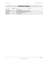
January 2011 March 2011 Revision Number 0.3 0.5 0.7 0.9 1.0 Modifications Initial release. Updated the hardware info and SE SKU. Updated S1200BTS info and BIOS setup page. Updated S1200BT video mode. Corrected typos. Intel®Server Board S1200BT TPS ii Revision 1.0 Intel order number G13326-003 - Intel DBS1200BTS | Product Specification - Page 3
. The Intel® Server Board S1200BT may contain design defects or errors known as errata which may cause the product to deviate from published specifications. Current characterized errata are available on request. Intel Corporation server boards contain a number of high-density VLSI and power delivery - Intel DBS1200BTS | Product Specification - Page 4
Outline ...1 1.2 Server Board Use Disclaimer 1 2. Overview ...2 2.1 Intel® Server Board S1200BT Feature Set 2 2.2 Server Board Layout 4 2.2.1 2.2.2 Server Board Connector and Component Layout 5 Intel® Server Board S1200BTL Mechanical Drawings 8 2.2.3 Server Board Rear I/O Layout - Intel DBS1200BTS | Product Specification - Page 5
Intel®Server Board S1200BT TPS Table of Contents 3.6.4 Floppy Disk Controller 27 3.6.5 Keyboard and Mouse Support 28 3.6.6 Wake-up Control 28 3.7 3.7.1 3.7.2 Video Support ...28 Intel® Server Board S1200BTL 28 Video for Intel® Server Board S1200BTS 29 3.8 Network Interface Controller ( - Intel DBS1200BTS | Product Specification - Page 6
Intel® Server Board S1200BTS 46 5.1 Supper I/O...46 5.1.1 Key Features of supper I/O 46 6. BIOS User Interface...47 6.1 BIOS POST Initialization 47 6.1.1 BIOS Revision Identification 47 6.2 HotKeys Supported During POST 48 6.3 POST Logo Screen/Diagnostic Screen 49 6.4 BIOS Boot - Intel DBS1200BTS | Product Specification - Page 7
Guided Diagnostics 109 9.1 System Status LED (Only for S1200BTL 109 9.2 Post Code Diagnostic LEDs 109 10. Design and Environmental Specifications 111 10.1 Intel® Server Board S1200BT Design Specifications 111 10.2 Board-level Calculated MTBF 111 10.2.1 Processor Power Support 111 - Intel DBS1200BTS | Product Specification - Page 8
78 Figure 29.System Information Screen (S1200BTS 79 Figure 30. BMC LAN Configuration Screen (S1200BTL 80 Figure 31. Hardware Monitor Screen, Auto Fan Control (S1200BTS 81 Figure 32. Hardware Monitor Screen, Manual Fan Control (S1200BTS 81 viii Revision 1.0 Intel order number G13326-003 - Intel DBS1200BTS | Product Specification - Page 9
, J1F2, and J1E2) on S1200BTL 104 Figure 47. Jumper Blocks (J2G1, J1G1, J1H3, and J2J1) on S1200BTS 105 Figure 48. POST Code Diagnostic LED Location 110 Figure 49. Output Voltage Timing 115 Figure 50. Turn On/Off Timing (Power Supply Signals 116 Revision 1.0 ix Intel order number G13326-003 - Intel DBS1200BTS | Product Specification - Page 10
List of Tables Intel®Server Board S1200BT TPS List of Tables Table 1. Intel® Server Board S1200BT Feature Set 2 Table 2. Major Board Components 6 Table 3. Major Board Components 7 Table 4. Memory Configuration Table 20 Table 5. UDIMM memory configuration rule 20 Table 6. UDIMM Maximum - Intel DBS1200BTS | Product Specification - Page 11
40. One PCI X32 connector (J1B1 102 Table 41. SSI 4-pin Fan Header Pin-out 103 Table 42. Server Board Jumpers (J1F1, J1F2, J1F3, J1E2, and J4A2) on S1200BTL............104 Table 43. Server Board Jumpers (J2G1, J1G1, J1H3, and J2J1) on S1200BTS 105 Table 44. Front Panel LED Behavior Summary 109 - Intel DBS1200BTS | Product Specification - Page 12
List of Tables Intel®Server Board S1200BT TPS xii Revision 1.0 Intel order number G13326-003 - Intel DBS1200BTS | Product Specification - Page 13
Appendix C - POST Code Diagnostic LED Decoder Appendix D - POST Code Errors Appendix E - Supported Intel® Server Chassis Glossary Reference Documents 1.2 Server Board Use Disclaimer Intel Corporation server boards contain a number of high-density VLSI and power delivery components that need - Intel DBS1200BTS | Product Specification - Page 14
severs. It has two board SKUs, namely S1200BTL and S1200BTS. 2.1 Intel® Server Board S1200BT Feature Set Feature Processor Memory Chipset I/O Table 1. Intel® Server Board S1200BT Feature Set Description of S1200BTL Support for one Intel® Xeon® Processor E31200 Series or Intel® Core™ Processor i3 - Intel DBS1200BTS | Product Specification - Page 15
Intel® SAS Entry RAID Module card Two 6Gb/s SATA ports and four 3Gb/s SATA ports Intel® Embedded Server RAID Technology II through onboard SATA connectors provides SATA RAID 0, 1, and 10 and optional RAID 5 support provided by the Intel® RAID Activation Key AXXRAKSW5 Intel® Rapid Storage RAID - Intel DBS1200BTS | Product Specification - Page 16
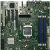
Overview 2.2 Server Board Layout Intel®Server Board S1200BT TPS Figure 1. Intel® Server Board S1200BTL Picture 4 Revision 1.0 Intel order number G13326-003 - Intel DBS1200BTS | Product Specification - Page 17
Intel®Server Board S1200BT TPS Overview Figure 2. Intel® Server Board S1200BTS Picture 2.2.1 Server Board Connector and Component Layout The following figure shows the board layout of the server board. Each connector and major component is identified by a number or letter, and Table 2 provides - Intel DBS1200BTS | Product Specification - Page 18
Intel®Server Board S1200BT TPS Figure 3. Intel® Server Board S1200BTL Layout Table 2. Major Board Components Description Description A Slot 1, 32 Mbit/33 MHz PCI R System FAN2 and System FAN3 Connector B TPM S CPU connector C Slot 3/4, PCI Express* Gen2 x4 (x8 connector) T CPU Fan connector - Intel DBS1200BTS | Product Specification - Page 19
Intel®Server Board S1200BT TPS Description L CPU Power Connector M SYS_FAN_4 N RMM4 Dedicated NIC connector O Four DIMM Slots P P/S AUX Q MAIN POWER Description CC HDD LED DD Internal USB Connector EE CMOS battery FF Four 3Gb/s SATA ports GG Two 6Gb/s SATA ports HH Smart module Overview Figure 4. - Intel DBS1200BTS | Product Specification - Page 20
Power connector J SYS_FAN_2 K DIMM slots L MAIN power connector M TPM connector Description P CPU Fan connector Q Chassis Intrusion R SATA_SGPIO S SYS_FAN_3 T Six 3Gb/s SATA ports U Low profile USB connector V Internal USB W CMOS battery X Front Panel Y HDD LED 2.2.2 Intel® Server Board S1200BTL - Intel DBS1200BTS | Product Specification - Page 21
Intel®Server Board S1200BT TPS Overview Figure 5. Intel® Server Board S1200BTL - Hole and Component Positions Revision 1.0 9 Intel order number G13326-003 - Intel DBS1200BTS | Product Specification - Page 22
Overview Intel®Server Board S1200BT TPS Figure 6. Intel® Server Board S1200BTL - Major Connector Pin Location (1 of 2) 10 Revision 1.0 Intel order number G13326-003 - Intel DBS1200BTS | Product Specification - Page 23
Intel®Server Board S1200BT TPS Overview Figure 7. Intel® Server Board S1200BTL - Major Connector Pin Location (2 of 2) Revision 1.0 11 Intel order number G13326-003 - Intel DBS1200BTS | Product Specification - Page 24
Overview Intel®Server Board S1200BT TPS Figure 8. Intel® Server Board S1200BTL - Primary Side Keepout Zone 12 Revision 1.0 Intel order number G13326-003 - Intel DBS1200BTS | Product Specification - Page 25
Intel®Server Board S1200BT TPS Overview Figure 9. Intel® Server Board S1200BTL - Secondary Side Keepout Zone Revision 1.0 13 Intel order number G13326-003 - Intel DBS1200BTS | Product Specification - Page 26
figure shows the layout of the rear I/O components for the server board. A Serial Port A B Video C NIC Port 1 (1 Gb) and Dual USB Port Connector D NIC port 2 (1 Gb) and Dual USB Port Connector Figure 10. Intel® Server Board S1200BT Rear I/O Layout 14 Revision 1.0 Intel order number G13326-003 - Intel DBS1200BTS | Product Specification - Page 27
of the functionality associated with each chipset component and the architectural blocks that make up the server board. Intel® Server Board S1200BTL Block Diagram ATX - 12" x 9.6" Slot 6 Slot 5 Slot 4 Slot 3 (x16 connector) (x8 connector) (x8 connector) Mezzanine Module PCIe Gen2 x8 PCIe - Intel DBS1200BTS | Product Specification - Page 28
Functional Architecture Intel®Server Board S1200BT TPS Slot 7 Slot 6 Intel® Server Board S1200BTS Block Diagram VTT VRD 12.0 VSA VPLL VCORE (x16 connector) (x8 connector) PCIe Gen2 x8 PCIe Gen2 x8 Intel® Xeon® Processor Knoxvill Socket H2 E3-1200 DDR3 (Channel A) DDR3 (Channel B) ATX - - Intel DBS1200BTS | Product Specification - Page 29
65 W Thermal Design Power (TDP); processors with higher TDP are not supported. The server board does not support previous generations of the Intel® Core™ Processor i3 Series. The list of supported processors may be found at http://serverconfigurator.intel.com. 3.1.3 Intel® Turbo Boost Technology - Intel DBS1200BTS | Product Specification - Page 30
Memory Supported The Intel® Server Board S1200BT family supports various DDR3 DIMM modules of different types and sizes and speeds. In this section, the statements of support are subject to qualification in two ways: For S1200 Server Boards with an SNB-DT processor, the Server Board and the BIOS - Intel DBS1200BTS | Product Specification - Page 31
system beeps and halts with POST Diagnostic LED code 0xEA staying displayed. 0xEB - Memory Test Error: If a DDR3 DIMM or a set of DDR3 DIMMs on the same memory channel fails memory testing but usable memory remains available, the BIOS emits a beep code and displays POST Diagnostic LED code 0xEB - Intel DBS1200BTS | Product Specification - Page 32
Functional Architecture Intel®Server Board S1200BT TPS The maximum memory bandwidth is 10.6 GB/s in Single-Channel mode or 21 GB/s in Dual-Channel Symmetric mode, assuming DDR3 running at 1333 MT/s. 3.2.3.1 Memory Configuration Table Table 4. Memory Configuration Table Configuration 1 DIMM - Intel DBS1200BTS | Product Specification - Page 33
RAS Support For Intel® Server Board S1200BT, the form of Memory RAS provided is Error Correction Code (ECC). ECC uses ―extra bits‖ - 64-bit data in a 72-bit DRAM array - to add an 8-bit calculated ―Hamming Code‖ to each 64 bits of data. This additional encoding enables the memory controller to - Intel DBS1200BTS | Product Specification - Page 34
The PCI-E configurations for each SKU are defined below: Intel® Server Board S1200BTL One PCI-E x16 connector to be used as a x8 link, two PCI-E x8 connectors to be used as a x4 link and one SAS module connector to be used as a x4 link connected to the PCI-E ports of the processor. One PCI-E x8 - Intel DBS1200BTS | Product Specification - Page 35
of the server board. Two internal 2x5 headers (J1E1 and J1D1) are provided, each supporting two optional USB 2.0 ports. One port on internal smart module connector (J1J2) on Intel® Server Board S1200BTL. 3.4.5.1 Native USB Support During the power-on self test (POST), the BIOS initializes and - Intel DBS1200BTS | Product Specification - Page 36
the optional Intel® SAS Entry RAID Module is detected, the x4 PCI Express* links from the chipset to the SAS Mezzanine slot. Four modules are supported in this platform: AXXRMS2AF040, AXXRMS2LL040 and AXX4SASMOD. 3.6 Integrated Baseboard Management Controller The Intel® Server Board S1200BTL has - Intel DBS1200BTS | Product Specification - Page 37
Intel®Server Board S1200BT TPS Functional Architecture JTAG Master Eight I2C interfaces with master-slave and SMBus timeout support. All interfaces are SMBus 2.0 compliant. Parallel general-purpose I/O Ports (16 direct, 32 shared) Serial general-purpose I/O Ports (80 in and 80 out) Three - Intel DBS1200BTS | Product Specification - Page 38
Functional Architecture Intel®Server Board S1200BT TPS Figure 13. Integrated BMC Hardware 3.6.1 Integrated BMC Embedded LAN Channel The Integrated BMC hardware includes two dedicated 1000M network interfaces. Interface 1: This interface is available from either of the available NIC ports in - Intel DBS1200BTS | Product Specification - Page 39
(J1B2 on S1200BTL or J8A1 on S1200BTS) Pin-out Pin 1 2 3 4 5 6 7 8 9 Signal Name DCD DSR RX RTS TX CTS DTR RI GND Serial Port B Header Pin-out 3.6.4 Floppy Disk Controller The server board does not support a floppy disk controller interface. However, the system BIOS recognizes USB floppy - Intel DBS1200BTS | Product Specification - Page 40
to power on and power off the system. 3.7 Video Support 3.7.1 Intel® Server Board S1200BTL The server board includes on-board Server Engine* LLC Pilot III* Controller with 128 MB DDR3 memory in which 8MB is usable/accessible memory for iBMC video/graphic display functions. The graphic controller - Intel DBS1200BTS | Product Specification - Page 41
Slave interface PCI 2.1 compliant Memory control is provided for the 4MB internal memory Support 640x480, 800x600, 1024x768 resolution and up to 85Hz. Dual Video mode is supported. 3.8 Network Interface Controller (NIC) The Intel® Server Board S1200BT supports two network interfaces, One is - Intel DBS1200BTS | Product Specification - Page 42
(Sx). In SMBus mode, the link speed is reduced to 10 Mb/s (dependent on low power options). The PCIe interface incorporates two aspects: a PCIe SerDes (electrically) and a custom logic protocol. 3.8.3 MAC Address Definition Each Intel® Server Board S1200BTL has the following four MAC addresses - Intel DBS1200BTS | Product Specification - Page 43
Intel®Server Board S1200BT TPS Functional Architecture 3.11 TPM (Trusted Platform Module) There is one TPM module connector. The detail information is listed below: Embedded TPM 1.2 firmware 33-MHz Low Pin Count (LPC) interface V1.1 Compliant with TCG PC client specific TPM Implementation - Intel DBS1200BTS | Product Specification - Page 44
management firmware. The following diagram provides an overview of the Server Management Bus (SMBUS) architecture used on this server board. MM[0] IPMB (3.3V STBY) Voltage Translation IPMB (5V STBY) M/S IPMB Connector MM[1] MM[2] Sensor (3.3V STBY) S S BB sensor2 Front-Panel S Front-Panel - Intel DBS1200BTS | Product Specification - Page 45
. This list does not preclude support for future enhancements or additions. In-circuit BMC firmware update Fault resilient booting (FRB): FRB2 is supported by the watchdog timer functionality. Chassis intrusion detection Basic fan control using TControl version 2 SDRs Power supply - Intel DBS1200BTS | Product Specification - Page 46
Board S1200BT TPS Signal testing support: The BMC provides test commands for setting and getting platform signal states. The BMC generates diagnostic beep codes for fault conditions. System GUID storage and retrieval Front panel management: The BMC controls the system status LED and chassis - Intel DBS1200BTS | Product Specification - Page 47
In-circuit BMC Firmware Update FRB 2 Chassis Intrusion Detection Fan Redundancy Monitoring Hot-Swap Fan Support Acoustic Management Diagnostic Beep Code Support Power State Retention ARP/DHCP Support PECI Thermal Management Support E-mail Alerting Embedded Web Server SSH Support Integrated KVM - Intel DBS1200BTS | Product Specification - Page 48
Board S1200BT TPS 4.2.1 Enabling Advanced Management Features The Advanced management features are to be delivered as part of the Integrated BMC firmware image. The Integrated BMC's baseboard SPI flash contains code/data for both the Basic and Advanced features. An optional add-in card Intel - Intel DBS1200BTS | Product Specification - Page 49
As the server is powered up, the remote KVM session displays the complete BIOS boot process. The user is able interact with BIOS setup, change and save settings as well as enter and interact with option ROM configuration screens. At least two concurrent remote KVM sessions are supported. It is - Intel DBS1200BTS | Product Specification - Page 50
a server reset or power on/off. An Integrated BMC reset (e.g. due to an Integrated BMC reset after Integrated BMC firmware update) will require the session to be re-established The mounted device is visible to (and useable by) managed system's OS and BIOS in both pre-boot and post-boot states - Intel DBS1200BTS | Product Specification - Page 51
Intel®Server Board S1200BT TPS Platform Management 4.2.3.1 Availability The default inactivity timeout is 30 minutes and is not user-configurable. Media redirection sessions persist across system reset but not across an AC power loss or BMC reset. 4.2.3.2 Network Port Usage The KVM and media - Intel DBS1200BTS | Product Specification - Page 52
the system has been updated to support these advanced features. A partial list of additional features supported by the web GUI includes: Presents all the Basic features to the users. Power on/off/reset the server and view current power state. Virtual front panel display and overall system - Intel DBS1200BTS | Product Specification - Page 53
Intel®Server Board S1200BT TPS Platform Management A list of data that may be captured using this feature includes but is not limited to: 1. Platform sensor readings - This includes all ―readable‖ sensors that can be accessed by the Integrated BMC firmware and have associated SDRs populated in the - Intel DBS1200BTS | Product Specification - Page 54
the server board. It allows the user to select which supported chassis (Intel® or Non-Intel) and platform chassis configuration is used. Based on the input provided, the FRUSDR writes sensor data specific to the configuration to NVRAM for the BMC controller to read each time the system is powered on - Intel DBS1200BTS | Product Specification - Page 55
Intel®Server Board S1200BT TPS Platform Management The NM feature is implemented by a complementary architecture utilizing the ME, Integrated BMC, BIOS, and an ACPI-compliant OS. The ME provides the NM policy engine and power control/limiting functions (referred to as Node Manager or NM) while the - Intel DBS1200BTS | Product Specification - Page 56
on power supplies in specific scenarios. IPMI-based commands over SMBus (monitoring, control & alert) Interfaces PECI Proxy and Pass-Through (this feature is also available on the ME Si-Enabling firmware) Power telemetry from Integrated BMC or from PMBus-compliant power supplies Note - Intel DBS1200BTS | Product Specification - Page 57
Intel®Server Board S1200BT TPS Platform Management Alerts that signify fault conditions that should be recorded in the system SEL will be sent to the Integrated BMC by the ME using the IPMI Platform Event Message command. The Integrated BMC deposits such events into the SEL. The external software - Intel DBS1200BTS | Product Specification - Page 58
Configuration and Power Interface) Support up to 2 16550-compatible UARTs ports 8042-based keyboard controller Smart Fan control system Five fan-speed monitoring inputs Four fan-speed controls GPIO Support PECI 1.0 and 1.1a Specifications 46 Revision 1.0 Intel order number - Intel DBS1200BTS | Product Specification - Page 59
BIOS builds for S1200BT server boards. OEMID = Three-character OEM BIOS Identifier, to identify the board BIOS ―owner‖. Changed only if and when BIOS Development management authorizes a BIOS program for a specific OEM customer. -―86B‖ is used for BIOS Releases. MajorVer = Major Version, two - Intel DBS1200BTS | Product Specification - Page 60
. The Server Board BIOS recognizes a number of HotKeys during POST. After the OS is booted, HotKeys are the responsibility of the OS and the OS defines its own set of recognized HotKeys. Following are the POST HotKeys, with the functions they cause to be performed. 48 Revision 1.0 Intel order - Intel DBS1200BTS | Product Specification - Page 61
Intel®Server Board S1200BT TPS BIOS User Interface Table 13. POST HotKeys Recognized HotKey Combination Function Enter Setup Pop up BIOS Boot Menu Network boot 6.3 POST Logo Screen/Diagnostic Screen The Logo Screen/Diagnostic Screen appears in one of two forms: If Quiet Boot - Intel DBS1200BTS | Product Specification - Page 62
Intel®Server Board S1200BT TPS 6.4 BIOS Boot Pop-up Menu The BIOS Boot Specification (BBS) provides a Boot Pop-up menu that can be invoked by pressing the key during POST. The BBS Pop-up menu displays all available boot devices. The boot order in the pop-up menu is not the same as the boot - Intel DBS1200BTS | Product Specification - Page 63
Intel®Server Board S1200BT TPS BIOS User Interface Note: If an Administrative Password has not been set, anyone who boots the system to Setup has access to all selection and data entry fields in Setup and can change any of them. 6.5.1.1 Setup Page Layout The Setup page layout is sectioned into - Intel DBS1200BTS | Product Specification - Page 64
User Interface Intel®Server Board S1200BT TPS Each Setup menu page contains a number of features. Each was pressed, without affecting any existing settings. If ―Yes‖ is selected and the key is pressed, the setup is exited and the BIOS returns to the main System Options Menu screen. - Intel DBS1200BTS | Product Specification - Page 65
Intel®Server Board S1200BT TPS BIOS User Interface Key Option Save and Exit Description Pressing the key causes the following message to display: Save configuration and reset? Yes No If ―Yes‖ is highlighted and is pressed, all changes are saved and the Setup is exited. If ―No - Intel DBS1200BTS | Product Specification - Page 66
BIOS User Interface Intel®Server Board S1200BT boot the system according to the boot order set from the last boot. 6.5.2.1 Map of Screens and Functionality There are a number of screens in the entire Setup Processor Configuration Memory Configuration Mass Storage Controller Configuration Serial - Intel DBS1200BTS | Product Specification - Page 67
Intel®Server Board S1200BT TPS Categories (Top Tabs) Security Screen (Tab) Server Management Screen (Tab With BMC Only] [Non-BMC Only] - 2nd Level Screens - - Console Redirection System Information BMC LAN Configuration Hardware Monitor [Non-BMC Only] Boot Options Screen (Tab) Hard Disk - Intel DBS1200BTS | Product Specification - Page 68
Intel®Server Board S1200BT TPS 6.5.2.2 Main Screen (Tab) The Main Screen is the first screen that appears when the BIOS Setup configuration utility is entered, unless an error has occurred. If an error has occurred, the Error Manager Screen appears instead. Main Advanced Security Server - Intel DBS1200BTS | Product Specification - Page 69
Intel®Server Board S1200BT TPS BIOS User Interface Screen Field Descriptions: 1. Logged in as: Option Values: Help Text: Comments: Information only. Displays password level that setup is running in: Administrator or User. With no passwords set, Administrator is - Intel DBS1200BTS | Product Specification - Page 70
Intel®Server Board S1200BT TPS [Enabled] - Display the logo screen during POST. [Disabled] - Display the diagnostic screen during POST. 7. POST Error Pause Option Values: Enabled Disabled Help Text: [Enabled] - Go to the Error Manager for critical POST errors. [Disabled] - Attempt to boot - Intel DBS1200BTS | Product Specification - Page 71
Intel®Server Board S1200BT TPS BIOS User Interface Main Advanced Security Server Management Boot Options Boot Manager ► Processor Configuration ► Memory Configuration ► Mass Storage Controller Configuration ► Serial Port Configuration ► USB Configuration ► PCI Configuration ► System Acoustic and - Intel DBS1200BTS | Product Specification - Page 72
BIOS User Interface Intel®Server Board S1200BT TPS Screen Field Descriptions: 1. Processor Configuration Option Values: Help Text: View/Configure processor information and settings. Comments: Selection only. Position to this line and press the key to go to the Processor - Intel DBS1200BTS | Product Specification - Page 73
Intel®Server Board S1200BT TPS BIOS User Interface Comments: Selection only. Position to this line and press the key to go to the PCI Configuration group of configuration settings. 7. System Acoustic and Performance Configuration Option Values: Help Text: View/Configure - Intel DBS1200BTS | Product Specification - Page 74
Remapping Pass-through DMA Support Hardware Prefetcher Adjacent Cache Line Prefetch Intel®Server Board S1200BT TPS Enabled/Disabled Enabled/Disabled Power Optimized/Traditional Enabled/Disabled - Intel DBS1200BTS | Product Specification - Page 75
Intel®Server Board S1200BT TPS BIOS User Interface Screen Field Descriptions: 1. Processor ID Option Values: Help Text: Comments: Information only. Displays the Processor Signature value (from the CPUID instruction) identifying the type of processor and the stepping Processor - Intel DBS1200BTS | Product Specification - Page 76
BIOS User Interface Intel®Server Board S1200BT TPS Option Values: Help Text: Comments: Information only. Displays Brand ID string read from processor with CPUID instruction. 7. Intel® Turbo Boost Technology Option Values: Enabled Disabled Help Text: Intel® - Intel DBS1200BTS | Product Specification - Page 77
Intel®Server Board S1200BT TPS BIOS User Interface Help Text: Enable/Disable Processor C3 (ACPI C2/C3) Help Text: Intel® Hyper-Threading Technology allows multithreaded software applications to execute threads in parallel within each processor. Contact your OS vendor regarding OS support of this - Intel DBS1200BTS | Product Specification - Page 78
User Interface Intel®Server Board S1200BT TPS 15. Intel® Virtualization Technology Option Values: Enabled Disabled Help Text: Intel® Virtualization Technology allows a platform to run multiple operating systems and applications in independent partitions. Note: A change to this option requires - Intel DBS1200BTS | Product Specification - Page 79
Intel®Server Board S1200BT TPS BIOS User Interface Comments: This option is only visible if all processors installed in the system support Intel® VT. The software configuration installed on the system must support this feature in order for it to be enabled. 16. Intel® VT for Directed I/O Option - Intel DBS1200BTS | Product Specification - Page 80
Interface Intel®Server Board S1200BT TPS Note: Modifying this setting may key to return to the Advanced screen, then select the desired screen. Advanced Memory Configuration Screen Field Descriptions: Total Memory Effective Memory Current Configuration Current Memory Speed Memory Operating Speed - Intel DBS1200BTS | Product Specification - Page 81
Intel®Server Board S1200BT TPS BIOS User Interface Screen Field Descriptions: 1. Total Memory Option Values: Help Text: Comments: Information only. Displays the amount of memory available in the system in the form of installed DDR3 DIMMs, - Intel DBS1200BTS | Product Specification - Page 82
User Interface Intel®Server Board S1200BT TPS 3. Current Configuration Option Values: Single Channel Dual Channel Symmetric Intel® Flex Help Text: Comments: Displays one of the following: Single Channel - DIMMs are operating in Single Channel mode. This is the configuration when - Intel DBS1200BTS | Product Specification - Page 83
to configure the SATA or SAS controller when it is present on the server board, midplane or backplane of an Intel® system. To access this screen from the Main screen, select Advanced > Mass Storage Controller Configuration. To move to another screen, press the key to return to the Advanced - Intel DBS1200BTS | Product Specification - Page 84
Address IRQ Intel®Server Board S1200BT TPS Enabled/Disabled 3F8h/2F8h/3E8h/2E8h 3 or 4 Enabled/Disabled 3F8h/2F8h/3E8h/2E8h 3 or 4 Figure 20. Serial Port Configuration Screen 6.5.2.8 USB Configuration The USB Configuration screen allows the user to configure the USB controller options. To - Intel DBS1200BTS | Product Specification - Page 85
Intel®Server Board S1200BT TPS BIOS User Interface Advanced USB Configuration Detected USB Devices USB Controller Legacy USB Support Port 60/64 Emulation Make USB Devices Non-Bootable Enabled/Disabled Enabled/Disabled/Auto Enabled/Disabled Enabled/Disabled USB - Intel DBS1200BTS | Product Specification - Page 86
Intel®Server Board S1200BT TPS Figure 22. PCI Configuration Screen 10. Wake on LAN (PME) Option Values: Enabled Disabled Help Text: Enables or disables PCI PME function for Wake on LAN capability from LAN adapters. Comments: Enables/disables PCI/PCIe PME# signal to generate Power Management - Intel DBS1200BTS | Product Specification - Page 87
arrow keys to traverse the tabs at the top of the Setup screen until the Security screen is selected. Main Advanced Security Server Management Boot Options Boot Manager Administrator Password Status User Password Status Set Administrator Password Set User Password Front Panel Lockout - Intel DBS1200BTS | Product Specification - Page 88
and controlling the BMC LAN configuration. To access this screen from the Main screen or other top-level Tab screen, press the right or left arrow keys to traverse the tabs at the top of the Setup screen until the Server Management screen is selected. Main Advanced Security Server Management Boot - Intel DBS1200BTS | Product Specification - Page 89
Intel®Server Board S1200BT TPS BIOS User Interface Main Advanced Security Server Management Boot Options Boot Manager Assert NMI on SERR Assert NMI on PERR Resume on AC Power Loss Clear System Event Log FRB-2 Enable O/S Boot Watchdog Timer O/S Boot Watchdog Timer Policy O/S Boot Watchdog Timer - Intel DBS1200BTS | Product Specification - Page 90
key to return to the Server Management screen, then select the desired screen. System Information Board Part Number Board Serial Number System Part Number System Serial Number Chassis Part Number Chassis Serial Number Asset Tag BMC Firmware Revision HSC Firmware Revision ME Firmware Revision - Intel DBS1200BTS | Product Specification - Page 91
Intel®Server Board S1200BT TPS System Information Board Part Number Board Serial Number System Part Number System Serial Number Chassis Part Number Chassis Serial Number Asset Tag HSC Firmware Revision ME Firmware Revision UUID Server Management - Intel DBS1200BTS | Product Specification - Page 92
/edit] Figure 30. BMC LAN Configuration Screen (S1200BTL) 6.5.2.16 Hardware Monitor The Hardware Monitor screen allows the user to configure Fan Speed Control and to view displays of temperature and voltage status. To access this screen from the Main screen, select Server Management > Hardware - Intel DBS1200BTS | Product Specification - Page 93
Intel®Server Board S1200BT TPS Hardware Monitor Server Management ► Real-time Temperature and Voltage Status Fan Controller Auto / Manual CPU Fan Altitude System Fan Altitude 300m/900m/1500m/3000m 300m/900m/1500m/3000m BIOS User Interface Figure 31. Hardware Monitor Screen, Auto Fan Control - Intel DBS1200BTS | Product Specification - Page 94
BIOS User Interface Intel®Server Board S1200BT TPS To access this screen from the Main screen, select Server Management > Hardware Monitor > Realtime Temperature and Voltage Status. To move to another screen, press the key to return to the Hardware Monitor screen, if necessary press the - Intel DBS1200BTS | Product Specification - Page 95
Intel®Server Board S1200BT TPS BIOS User Interface Main Advanced Security Server Management Boot Options Boot Manager System Boot Timeout Boot Option #1 Boot Option #2 Boot Option #n ► Hard Disk Order ► CDROM Order ► Floppy Order ► Network Device Order ► BEV Device Order ► Add EFI Boot Option ► - Intel DBS1200BTS | Product Specification - Page 96
Disk #1 Hard Disk #2 Intel®Server Board S1200BT TPS Boot Options Figure 35. Hard Disk Order Screen 6.5.2.20 CDROM Order The CDROM Order screen allows the user to control the order in which BIOS attempts to boot from the CDROM drives - Intel DBS1200BTS | Product Specification - Page 97
Intel®Server Board S1200BT TPS Floppy Order Floppy Disk #1 Floppy Disk #2 BIOS User Interface Boot Options Figure 37. Floppy Order Screen 6.5.2.22 Network Device Order The Network Device Order screen allows the user to control the - Intel DBS1200BTS | Product Specification - Page 98
BEV Device #1 BEV Device #2 Intel®Server Board S1200BT TPS Boot Options Figure 39. BEV Device Order Screen 6.5.2.24 Add EFI Boot Option The Add EFI Boot Option screen allows the user to add an EFI boot option to the boot order. This screen is only - Intel DBS1200BTS | Product Specification - Page 99
Intel®Server Board S1200BT TPS Delete EFI Boot Option Delete Boot Option BIOS User Interface Boot Options Select one to Delete/Internal EFI Shell Figure 41. Delete EFI Boot Option Screen 6.5.2.26 Boot Manager Screen (Tab) The Boot Manager screen allows the user to view a list of devices - Intel DBS1200BTS | Product Specification - Page 100
ERROR CODE Exit SEVERITY INSTANCE Intel®Server Board S1200BT TPS Figure 43. Error Manager Screen 6.5.2.28 System Event Log Screen (Tab) The System Event Log screen appears only for server boards (other than Compute Module boards) which do not have an onboard Baseboard Management Controller - Intel DBS1200BTS | Product Specification - Page 101
Intel®Server Board S1200BT TPS BIOS User Interface 6.5.2.29 Exit Screen (Tab) The Exit screen allows the user to choose whether to save or discard the configuration changes made on other Setup screens. It also allows the user to restore the BIOS settings to the factory defaults or to save or - Intel DBS1200BTS | Product Specification - Page 102
on S1200BTL Connector Quantity Reference Designators Connector Type Power supply 3 CPU 1 Main memory 4 Intel® RMM4 Lite 1 Intel® RMM4 1 Dedicated NIC SAS Module 1 CPU Fan 1 System Fans 4 Battery 1 NIC/Stack 2x USB 2 Video 1 Serial port A 1 Serial port B 1 Front panel - Intel DBS1200BTS | Product Specification - Page 103
Connector Type Pin Count Power supply 2 CPU 1 Main memory 4 CPU Fan 1 System Fans 3 Battery 1 NIC/Stack 2x USB 2 Video 1 Serial port A 1 Front panel 1 USB Internal 1 Header PCI-E x16 1 PCI-E x8 2 PCI 32 1 Chassis Intrusion 1 3Gb/s Serial ATA 6 SATA RAID key - Intel DBS1200BTS | Product Specification - Page 104
and Dedicated NIC connector An Intel® RMM 4 lite connector (J4B1) is included on the server board to support the optional Intel® Remote Management Module 4 lite. This server board does not support third-party management cards. Note: This connector is not compatible with the Intel® Remote Management - Intel DBS1200BTS | Product Specification - Page 105
Control Panel Connector The server board provides a 24-pin SSI front panel connector (J1C1) for use with Intel® and third-party chassis. The following table provides the pin-out for this connector. Table 26. Front Panel SSI Standard 24-pin Connector Pin-out (J1C1 on S1200BTL or J1C2 on S1200BTS - Intel DBS1200BTS | Product Specification - Page 106
the bridge board connector at location J1C1 as is implemented in Intel® Server Systems configured using a bridge board and a hot- swap backplane. 7.4.1 Power Button The BIOS supports a front control panel power button. Pressing the power button initiates a request that the Integrated BMC forwards - Intel DBS1200BTS | Product Specification - Page 107
Intel®Server Board S1200BT TPS Connector/Header Locations and Pin-outs 7.4.2 Reset Button The platform supports a front control panel reset button. Pressing the reset button initiates a request forwarded by the Integrated BMC to the chipset. The BIOS does not affect the behavior of the reset - Intel DBS1200BTS | Product Specification - Page 108
Header Locations and Pin-outs Intel®Server Board S1200BT TPS 7.5 I/O Connectors 7.5.1 VGA Connector The following table details the pin-out definition of the VGA connector (J7A1 on S1200BTL and J6A1 on S1200BTS): Table 28. VGA Connector Pin-out Pin Signal Name 1 V_IO_R_CONN 2 V_IO_G_CONN - Intel DBS1200BTS | Product Specification - Page 109
SATA The sever board provides up to two 6Gb/s SATA connectors and four 3Gb/s SATA connectors. The pin configuration for each connector is identical and differential pair Ground 7.5.4 SAS Connectors The Intel® Server Board S1200BTL provides one SAS connector. The pin configuration is identical - Intel DBS1200BTS | Product Specification - Page 110
/Header Locations and Pin-outs Intel®Server Board S1200BT TPS Table 33. SAS Connector Pin-out (J2H1) Pin Signal Name 1 GND 2 ) RXD (receive data) TXD (Transmit data) DTR (Data terminal ready) Ground DSR (data set ready) RTS (request to send) CTS (clear to send) RI (Ring Indicate) Table 35 - Intel DBS1200BTS | Product Specification - Page 111
7 Ground 8 Ground 9 Key 10 TP_USB_ICH_NC Description USB power (port 4) USB power (port 5) USB port 4 negative signal USB port 5 negative signal USB port 4 positive signal USB port 5 positive signal No pin Test point One 2x5 connectors on the server board provides an option to support Smart module - Intel DBS1200BTS | Product Specification - Page 112
Connector/Header Locations and Pin-outs Intel®Server Board S1200BT TPS 7.6 PCI Express* Slot/PCI Slot/Riser Card Slot A PCI-E Riser card will enable a PCI-E add-on card to be accommodated in the 1U chassis A10 A11 KEY PRSNT1_N +12V +12V GND JTAG2 JTAG3 JTAG4 JTAG5 +3_3V +3_3V PERST_N KEY A12 GND - Intel DBS1200BTS | Product Specification - Page 113
Intel®Server Board S1200BT TPS Connector/Header Locations and Pin-outs Pin Signal B39 GND B40 GND B41 PETP6 B42 PETN6 B43 GND B44 GND B45 PETP7 B46 PETN7 B47 GND NC NC GND GND NC NC GND GND NC NC GND GND NC NC GND GND NC NC GND GND NC NC GND Revision 1.0 101 Intel order number G13326-003 - Intel DBS1200BTS | Product Specification - Page 114
and Pin-outs Intel®Server Board S1200BT TPS Table 39. Three PCI Express* x8 connectors (J2B2, J3B1 and J4B2) Pin A1 A2 A3 A4 +5V INTB# INTD# PRSNT1# RSVD PRSNT2# GND GND RSVD Ground CLK Ground Table 40. One PCI X32 connector (J1B1) Pin # A1 A2 A3 A4 A5 A6 A7 A8 A9 A10 A11 A12 A13 A14 A15 A16 - Intel DBS1200BTS | Product Specification - Page 115
1 2 3 4 Signal Name Ground 12 V Fan Tach Fan PWM Type GND Power In Out Description Ground is the power supply ground Power supply 12 V FAN_TACH signal is connected to the Integrated BMC to monitor the fan speed FAN_PWM signal to control fan speed Revision 1.0 103 Intel order number G13326-003 - Intel DBS1200BTS | Product Specification - Page 116
J1F1: 1-2 Password Clear 2-3 J1F3: BIOS 1-2 Recovery 2-3 J4A2: BMC 1-2 Force Update 2-3 System Results These pins should have a jumper in place for normal system operation. (Default) If these pins are jumpered with AC power plugged, the CMOS settings are cleared within five seconds. These - Intel DBS1200BTS | Product Specification - Page 117
1-2 Clear 2-3 J1J2: ME Force 1-2 Update 2-3 J1G1: 1-2 Password Clear 2-3 J2G1: BIOS 1-2 Recovery 2-3 System Results These pins should have a jumper in place for normal system operation. (Default) If these pins are jumpered with AC power plugged, the CMOS settings are cleared within five - Intel DBS1200BTS | Product Specification - Page 118
to the BIOS Setup utility to reset the preferred settings. 8.1.2 Clearing the Password To clear the password, perform the following steps: 1. Power down the server. Do not unplug the power cord. 2. Open the chassis. For instructions, see your server chassis documentation. 3. Move jumper - Intel DBS1200BTS | Product Specification - Page 119
Intel®Server Board S1200BT TPS Jumper Blocks 8.2 Integrated BMC Force Update Procedure (Only for The Intel® Server Board S1200BTL) When performing the standard Integrated BMC firmware update procedure, the update utility places the Integrated BMC into an update mode, allowing the firmware to load - Intel DBS1200BTS | Product Specification - Page 120
Jumper Blocks Intel®Server Board S1200BT TPS 1. Power down and remove the AC power cord. 2. Open the server chassis. For instructions, see your server chassis documentation. 3. Move jumper from the default operating position (covering pins 1 and 2) to the enabled position (covering pins 2 and 3). - Intel DBS1200BTS | Product Specification - Page 121
for S1200BTL) The server board provides a system status indicator LED on the front panel. This indicator LED has specific states and corresponding interpretation as shown in the following table: LED Power/Sleep Status Global HDD Activity LAN 1-2 Chassis Identification Table 44. Front Panel LED - Intel DBS1200BTS | Product Specification - Page 122
Intel®Light Guided Diagnostics Intel®Server Board S1200BT TPS Figure 48. POST Code Diagnostic LED Location A Status LED B ID LED C Diagnostic LED #7 (MSB LED) D Diagnostic LED #6 E Diagnostic LED #5 F Diagnostic LED #4 G Diagnostic LED #3 H Diagnostic LED #2 I Diagnostic LED #1 J Diagnostic LED - Intel DBS1200BTS | Product Specification - Page 123
go to http://www.intel.com/support/motherboards/server to get the updated MTBF report for Intel® Server Board S1200BT family. 10.2.1 Processor Power Support The server board supports the Thermal Design Power (TDP) guideline for Intel® Xeon® processor. The Flexible Motherboard Guidelines (FMB) was - Intel DBS1200BTS | Product Specification - Page 124
a power supply for use with this server board. This section specifies the power supply requirements Intel® used to develop a power supply for the Intel® Server System R1304BTLSHBN. The following tables define two power and current ratings for this 350-W power supply. The combined output power of - Intel DBS1200BTS | Product Specification - Page 125
Intel®Server Board S1200BT TPS Design and Environmental Specifications 10.3.1 Grounding The grounds of the power supply output connector pins provide the power return path. The output connector ground pins are connected to the safety ground (power supply is only a test specification. The step - Intel DBS1200BTS | Product Specification - Page 126
Specifications Intel®Server Board S1200BT TPS Output +5 VSB ∆ Step Load Size (See note 2) 0.5 A Load Slew Rate 0.25 A/µsec Test capacitive Load 20 µF Note: Step loads on each 12 V output may happen simultaneously and should be tested that way. 10.3.6 Capacitive Loading The power supply - Intel DBS1200BTS | Product Specification - Page 127
Intel®Server Board S1200BT TPS Design and Environmental Specifications The output voltages must rise from 10% to msec (Tvout_off) of each other when the power supply is turned off. Figure 49 and Figure 50 shows the timing requirements for the power supply being turned on and off via the AC input - Intel DBS1200BTS | Product Specification - Page 128
Environmental Specifications Intel®Server Board S1200BT TPS of PWOK. Measured at 80% of maximum load. Delay from PSON# active to output voltages within regulation limits. Delay from PSON# deactive to PWOK Turn On/Off Timing (Power Supply Signals) 116 Revision 1.0 Intel order number G13326-003 - Intel DBS1200BTS | Product Specification - Page 129
Intel®Server Board S1200BT TPS Design and Environmental Specifications 10.3.11 Residual Voltage Immunity in Standby Mode The power supply reset the power supply. 10.3.12.1 Over-current Protection (OCP) The power supply the power supply. Auto-recovery power pins of the power supply connector - Intel DBS1200BTS | Product Specification - Page 130
Design and Environmental Specifications Output Voltage -12 V +5 VSB Intel®Server Board S1200BT TPS Minimum (V) -13.3 5.7 Maximum (V) -14.5 6.5 118 Revision 1.0 Intel order number G13326-003 - Intel DBS1200BTS | Product Specification - Page 131
the boot process. If the server board hangs during POST, the LEDs display the last POST event run before the hang. Supports only unbuffered DDR3 DIMMs (UDIMMs). Does not support the mixing of RDIMMs and UDIMMs. The Intel® Remote Management Module 4 (Intel® RMM4) lite connector is not compatible - Intel DBS1200BTS | Product Specification - Page 132
BMC Sensor Tables Intel®Server Board S1200BT TPS Appendix B: Integrated BMC Sensor Tables Intel® Server Board S1200BTL implements the below sensors: Sensor Type Codes Sensor table given below lists the sensor identification numbers and information regarding the sensor type, name, supported - Intel DBS1200BTS | Product Specification - Page 133
Intel®Server Board S1200BT TPS Appendix B: Integrated BMC Sensor Tables T: Threshold value Rearm Sensors The rearm is a request for the event status for a sensor to be rechecked and updated upon a transition between good and bad states. Rearming the sensors can be done manually or automatically. - Intel DBS1200BTS | Product Specification - Page 134
Appendix B: Integrated BMC Sensor Tables Intel®Server Board S1200BT TPS Full Sensor Name (Sensor name in SDR) Power Unit Status (Pwr Unit Status) Sensor # Platform Applicability 01h All Sensor Type Power Unit 09h Table 56. BMC Core Sensors Event/Reading Type Sensor Specific 6Fh Event Offset - Intel DBS1200BTS | Product Specification - Page 135
Specific 6Fh Sensor Specific 6Fh Event Offset Triggers 02 - Power down 03 - Power cycle 08 - Timer interrupt 00 - Chassis intrusion 04 - LAN leash lost Contrib. To System Status OK Assert/Deassert As and De Readable Event Data Value/Offsets - Trig Offset 00 - Front panel NMI / diagnostic - Intel DBS1200BTS | Product Specification - Page 136
Intel®Server Board S1200BT TPS Full Sensor Name (Sensor name in SDR) Sensor # Platform Applicability Baseboard Temperature 3 (Inlet Temp) Hot-swap Backplane Temperature (HSBP Temp) Fan Tachometer Sensors (Chassis specific sensor names) 24h 29h 30h- 34h All All Chassisspecific Power Supply - Intel DBS1200BTS | Product Specification - Page 137
Intel®Server Board S1200BT TPS Appendix B: Integrated BMC Sensor Tables Full Sensor Name (Sensor name in SDR) Sensor # Platform Applicability Sensor Type Event/Reading Type Event Offset Triggers Power Supply 2 +12V % of Maximum Current Output 59h (PS2 Curr Out %) Power Supply 1 - Intel DBS1200BTS | Product Specification - Page 138
Integrated BMC Sensor Tables Intel®Server Board S1200BT TPS Full Sensor Name (Sensor name in SDR) Sensor # Platform Applicability Sensor Type Event/Reading Type Event Offset Triggers Power Supply 2 Fan Tachometer 1 A4h (PS2 Fan Tach 1) Power Supply 2 Fan Tachometer 2 A5h (PS2 Fan Tach - Intel DBS1200BTS | Product Specification - Page 139
Intel®Server Board S1200BT TPS Appendix B: Integrated BMC Sensor Tables Full Sensor Name (Sensor name in SDR) Threshold 01h Threshold 01h Threshold 01h Threshold 01h Threshold 01h Threshold 01h Threshold 01h Sensor Specific 6Fh Event Offset Triggers [u,l] [c,nc] [u,l] [c,nc] [u,l] [c,nc] [u,l] [c, - Intel DBS1200BTS | Product Specification - Page 140
Appendix B: Integrated BMC Sensor Tables Intel®Server Board S1200BT TPS Full Sensor Name (Sensor name in SDR) Hard Disk Drive 2 Status Type Drive Slot 0Dh Drive Slot 0Dh Event/Reading Type Sensor Specific 6Fh Sensor Specific 6Fh Event Offset Triggers Contrib. To System Status 07 - Rebuild - Intel DBS1200BTS | Product Specification - Page 141
Intel®Server Board S1200BT TPS Appendix C: POST Code Diagnostic LED Decoder Appendix C: POST Code Diagnostic LED Decoder During the system boot process, the BIOS executes a number of platform configuration processes, each of which is assigned a specific hex POST code number. As each configuration - Intel DBS1200BTS | Product Specification - Page 142
Appendix C: POST Code Diagnostic LED Decoder Intel®Server Board S1200BT TPS Progress Code 0x06 0x07 0x08 0x09 0x0E 0x0F 0x10 0x11 0x15 0x19 0x31 0x32 0x33 0x34 0x35 0x36 0x4F 0x60 0x61 0x62 0x63 0x68 0x69 0x6A 0x70 130 Diagnostic LED Decoder O = On, X=Off Upper Nibble Lower Nibble MSB 8h 4h 2h 1h - Intel DBS1200BTS | Product Specification - Page 143
Intel®Server Board S1200BT TPS Appendix C: POST Code Diagnostic LED Decoder Progress Code 0x71 0x72 0x78 0x79 0x90 0x91 0x92 0x93 0x94 0x95 0x96 0x97 0x98 0x99 0x9A 0x9B 0x9C 0x9D 0xA1 0xA2 0xA3 0xA4 0xA9 0xAB 0xAC 0xAD 0xAE 0xAF 0xB0 Diagnostic LED Decoder O = On, X=Off Upper Nibble Lower Nibble - Intel DBS1200BTS | Product Specification - Page 144
Code Diagnostic LED Decoder Intel®Server Board S1200BT TPS Progress Code 0xB1 0xB2 0xB3 0xB4 0xB5 0xB6 0xB7 0x00 0xF0 0xF1 0xF2 0xF3 0xF4 Diagnostic LED O O X O O O O X X X X BIOS Recovery Description RT Set Virtual Address Map End DXE Legacy Option ROM init DXE Reset system DXE USB Hot plug DXE - Intel DBS1200BTS | Product Specification - Page 145
Intel®Server Board S1200BT TPS Appendix D: POST Code Errors Appendix D: POST Code Errors The BIOS outputs the current boot progress codes on the video screen. Progress codes are 32bit quantities plus optional data. The 32-bit numbers include class, subclass, and operation information. The class - Intel DBS1200BTS | Product Specification - Page 146
Errors Intel®Server Board S1200BT TPS Error Code 8180 8190 8198 8300 8305 83A0 83A1 84F2 84F3 84F4 84FF 8500 8501 8520 8521 8523 8524 8540 8541 8543 8544 9667 9687 96A7 A000 A001 A002 A003 A100 A421 A5A0 A5A1 Error Message Processor 01 microcode update not found Watchdog timer failed on last boot - Intel DBS1200BTS | Product Specification - Page 147
Board S1200BT TPS Appendix D: POST Code Errors POST Error Beep Codes The following table lists POST error beep codes. Prior to system video initialization, the BIOS uses these beep codes to inform users on error conditions. The beep code is followed by a user-visible code on POST Progress LEDs - Intel DBS1200BTS | Product Specification - Page 148
E: Supported Intel®Server Chassis Intel®Server Board S1200BT TPS Appendix E: Supported Intel® Server Chassis The Intel® Server Board S1200BT is supported in the following Intel® server chassis: 1. Intel® Server Chassis P4304XXSFCN 2. Intel® Server Chassis P4304XXSHCN 136 Revision 1.0 Intel - Intel DBS1200BTS | Product Specification - Page 149
Metal-oxide-semiconductor In terms of this specification, this describes the PC-AT compatible region of battery-backed 128 bytes of memory, which normally resides on the server board. Dynamic Host Configuration Protocol Direct Platform Control Electrically Erasable Programmable Read-Only - Intel DBS1200BTS | Product Specification - Page 150
Engine Memory Management Unit Milliseconds Memory Type Range Register Multiplexor Network Interface Controller Non-maskable Interrupt Output Buffer Original Equipment Manufacturer Unit of electrical resistance Over-voltage Protection Intel order number G13326-003 Intel®Server Board S1200BT TPS - Intel DBS1200BTS | Product Specification - Page 151
Logic Device Platform Management Interrupt Power-On Self Test Power Supply Management Interface Pulse-Width Modulation QuickPath Interconnect Random Access Memory Reliability, Availability, Serviceability, Usability, and Manageability Reduced Instruction Set Computing Reduced Media-Independent - Intel DBS1200BTS | Product Specification - Page 152
Glossary Term ZIF Zero Insertion Force Definition Intel®Server Board S1200BT TPS 140 Revision 1.0 Intel order number G13326-003 - Intel DBS1200BTS | Product Specification - Page 153
Intel®Server Board S1200BT TPS Reference Documents Reference Documents Refer to the following documents for additional information: Intel® Server Board S1200BT BIOS External Product Specification Intel® Server Board S1200BT Common Core Integrated BMC External Product Specification Revision
-
 1
1 -
 2
2 -
 3
3 -
 4
4 -
 5
5 -
 6
6 -
 7
7 -
8
-
9
-
10
-
11
-
12
-
13
-
14
-
15
-
16
-
17
-
18
-
19
-
20
-
21
-
22
-
23
-
24
-
25
-
26
-
27
-
28
-
29
-
30
-
31
-
32
-
33
-
34
-
35
-
36
-
37
-
38
-
39
-
40
-
41
-
42
-
43
-
44
-
45
-
46
-
47
-
48
-
49
-
50
-
51
-
52
-
53
-
54
-
55
-
56
-
57
-
58
-
59
-
60
-
61
-
62
-
63
-
64
-
65
-
66
-
67
-
68
-
69
-
70
-
71
-
72
-
73
-
74
-
75
-
76
-
77
-
78
-
79
-
80
-
81
-
82
-
83
-
84
-
85
-
86
-
87
-
88
-
89
-
90
-
91
-
92
-
93
-
94
-
95
-
96
-
97
-
98
-
99
-
100
-
101
-
102
-
103
-
104
-
105
-
106
-
107
-
108
-
109
-
110
-
111
-
112
-
113
-
114
-
115
-
116
-
117
-
118
-
119
-
120
-
121
-
122
-
123
-
124
-
125
-
126
-
127
-
128
-
129
-
130
-
131
-
132
-
133
-
134
-
135
-
136
-
137
-
138
-
139
-
140
-
141
-
142
-
143
-
144
-
145
-
146
-
147
-
148
-
149
-
150
-
151
-
152
-
153
 |
 |
Intel
®
Server Board S1200BT
Technical Product Specification
Intel order number G13326-003
Revision 1.0
March, 2011
Enterprise Platforms and Services Division