Intel DC3217IYE Technical Product Specification
Intel DC3217IYE Manual
 |
View all Intel DC3217IYE manuals
Add to My Manuals
Save this manual to your list of manuals |
Intel DC3217IYE manual content summary:
- Intel DC3217IYE | Technical Product Specification - Page 1
G67686-002 The Intel Next Unit of Computing Board D33217GKE may contain design defects or errors known as errata that may cause the product to deviate from published specifications. Current characterized errata are documented in the Intel Next Unit of Computing Board D33217GKE Specification Update. - Intel DC3217IYE | Technical Product Specification - Page 2
First release of the Intel® Next Unit of Computing Board D33217GKE Technical Product Specification Specification Clarification Date October 2012 October 2012 Disclaimer This product specification applies to only the standard Intel® Next Unit of Computing Board with BIOS identifier GKPPT10H.86A - Intel DC3217IYE | Technical Product Specification - Page 3
the Specification Changes or Specification Clarifications that apply to the Intel® Desktop Board D33217GKE. Table 1. Specification Changes or Clarifications Date Type of Change Description of Changes or Clarifications October 2012 Spec Change Added Note to Section 1.6.1.3.1 on page 23. Errata - Intel DC3217IYE | Technical Product Specification - Page 4
Intel Desktop Board D33217GKE Technical Product Specification iv - Intel DC3217IYE | Technical Product Specification - Page 5
(TPS) specifies the board layout, components, connectors, power and environmental requirements, and the BIOS for Intel® Next Unit of Computing Board D33217GKE. Intended Audience The TPS is intended to provide detailed, technical information about Intel Next Unit of Computing Board D33217GKE and - Intel DC3217IYE | Technical Product Specification - Page 6
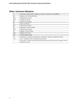
Intel Desktop Board D33217GKE Technical Product Specification Other Common Notation # GB GB/s Gb/s KB Kb kb 048,576 bytes) Megabytes per second Megabit (1,048,576 bits) Megabits per second Thermal Design Power An address or data value ending with a lowercase h indicates a hexadecimal value. Volts. - Intel DC3217IYE | Technical Product Specification - Page 7
Description 1.1 Overview 11 1.1.1 Feature Summary 11 1.1.2 Board Layout (Top 13 1.1.3 Board Layout (Bottom 15 1.1.4 Block Diagram 17 1.2 Online Support 18 1.3 Processor 18 1.4 System Memory 19 1.4.1 Memory Configurations 20 1.5 Intel® QS77 Express Chipset 22 1.5.1 Direct Media Interface - Intel DC3217IYE | Technical Product Specification - Page 8
Intel Desktop Board D33217GKE Technical Product Specification 2 Technical Reference 2.1 Memory Resources 35 2.1.1 Addressable Memory 35 2.1.2 Memory Map 37 2.2 Connectors and Headers 37 2.2.1 Back Panel Connectors 38 2.2.2 Connectors and Headers (Bottom 39 2.3 BIOS Setup Configuration Jumper - Intel DC3217IYE | Technical Product Specification - Page 9
36 9. Back Panel Connectors 38 10. Connectors and Headers (Bottom 39 11. Connection Diagram for Front Panel Header 44 12. Connection Diagram for Front Panel USB 2.0 Dual-Port Header 45 13. Location of the BIOS Configuration Setup Jumper 46 14. Board Dimensions 48 15. Localized High Temperature - Intel DC3217IYE | Technical Product Specification - Page 10
Intel Desktop Board D33217GKE Technical Product Specification Tables 1. Feature Summary 11 2. Components Shown in Figure 1 14 3. Components Shown in Figure 2 16 4. Supported Memory Configurations 19 5. LAN Connector LED States 27 6. Effects of Pressing the Power Switch 30 7. Power States and - Intel DC3217IYE | Technical Product Specification - Page 11
(PCI Express Full-Mini Card) for SSD support • One PCI Express Half-Mini Card connector • One PCI Express Full-Mini Card connector • Intel® BIOS resident in the Serial Peripheral Interface (SPI) Flash device • Support for Advanced Configuration and Power Interface (ACPI), Plug and Play, and System - Intel DC3217IYE | Technical Product Specification - Page 12
Intel Desktop Board D33217GKE Technical Product Specification Table 2. Feature Summary (continued) LAN Support Gigabit (10/100/1000 Mb/s) LAN subsystem using the Intel® 82579V Gigabit Ethernet Controller Hardware Monitor Subsystem Hardware monitoring subsystem, based on a Nuvoton NPCE791C - Intel DC3217IYE | Technical Product Specification - Page 13
Product Description 1.1.2 Board Layout (Top) Figure 1 shows the location of the major components on the top-side of Intel Next Unit of Computing Board D33217GKE. Figure 1. Major Board Components (Top) 13 - Intel DC3217IYE | Technical Product Specification - Page 14
Intel Desktop Board D33217GKE Technical Product Specification Table 3 lists the components identified in Figure 1. Table 3. Components Shown in Figure 1 Item from Figure 1 A B Description Battery Standby power LED C Processor fan header D Onboard power button E Power LED F Hard Disk - Intel DC3217IYE | Technical Product Specification - Page 15
Product Description 1.1.3 Board Layout (Bottom) Figure 2 shows the location of the major components on the bottom-side of Intel Next Unit of Computing Board D33217GKE. Figure 2. Major Board Components (Bottom) 15 - Intel DC3217IYE | Technical Product Specification - Page 16
Intel Desktop Board D33217GKE Technical Product Specification Table 4. Components Shown in Figure 2 Item from Figure 2 Description A Back panel connectors B PCI Express Full-Mini Card connector C PCI Express Half-Mini Card connector D Front panel dual-port USB 2.0 header E BIOS setup - Intel DC3217IYE | Technical Product Specification - Page 17
Product Description 1.1.4 Block Diagram Figure 3 is a block diagram of the major functional areas of the board. Figure 3. Block Diagram 17 - Intel DC3217IYE | Technical Product Specification - Page 18
Board D33217GKE Visit this World Wide Web site: http://www.intel.com/products/motherboard/index.htm http://www.intel.com/p/en_US/support?iid=hdr+support http://ark.intel.com Chipset information BIOS and driver updates Tested memory Integration information http://www.intel.com/products/desktop - Intel DC3217IYE | Technical Product Specification - Page 19
-DIMMs NOTE To be fully compliant with all applicable DDR SDRAM memory specifications, the board should be populated with SO-DIMMs that support the Serial Presence Detect (SPD) data structure. This allows the BIOS to read the SPD data and program the chipset to accurately configure memory settings - Intel DC3217IYE | Technical Product Specification - Page 20
Intel Desktop Board D33217GKE Technical Product Specification For information about... Tested Memory Refer to: http://support.intel.com/support/motherboards/desktop/sb /CS-025414.htm 1.4.1 Memory Configurations The processor supports the following types of memory organization: • Dual channel ( - Intel DC3217IYE | Technical Product Specification - Page 21
Product Description Figure 4 illustrates the memory channel and SO-DIMM configuration. Figure 4. Memory Channel and SO-DIMM Configuration 21 - Intel DC3217IYE | Technical Product Specification - Page 22
Intel Desktop Board D33217GKE Technical Product Specification 1.5 Intel® QS77 Express Chipset Intel QS77 Express Chipset with Direct Media Interface (DMI) interconnect provides interfaces to the processor and the USB, SATA, LPC, LAN, and PCI Express interfaces. The Intel QS77 Express Chipset is a - Intel DC3217IYE | Technical Product Specification - Page 23
1.6.1.1 Intel® High Definition (Intel® HD) Graphics The Intel HD graphics controller features the following: • 3D Features DirectX* 10.1 and Intel HD Technology with Advanced Hardware Video Transcoding Blu-ray* S3D via HDMI 1.4a Dynamic Video Memory Technology (DVMT) 5.0 support Support of - Intel DC3217IYE | Technical Product Specification - Page 24
AHCI Mode The board supports AHCI storage mode via the Intel QS77 Express Chipset. NOTE In order to use AHCI mode, AHCI must be enabled in the BIOS. Also, during Microsoft Windows XP installation, F6 must be pressed to install the AHCI drivers. See your Microsoft Windows XP documentation for more - Intel DC3217IYE | Technical Product Specification - Page 25
engine • Jumbo frame support • LAN connect interface between the PCH and the LAN controller • Power management capabilities ACPI technology support LAN wake capabilities • LAN subsystem software For information about LAN software and drivers Refer to http://downloadcenter.intel.com 25 - Intel DC3217IYE | Technical Product Specification - Page 26
Intel Desktop Board D33217GKE Technical Product Specification 1.9.1 Intel® 82579V Gigabit Ethernet Controller The Intel 82579V Gigabit Ethernet Controller supports the following features: • 10/100/1000 BASE-T IEEE 802.3 compliant • Energy Efficient Ethernet (EEE) IEEE802.3az support (Low Power Idle - Intel DC3217IYE | Technical Product Specification - Page 27
the board is powered up and the LAN subsystem is operating. Table 6. LAN Connector LED States LED LED Color LED State Off Link Green On Blinking Off Data Rate Green/Yellow Green Yellow Condition LAN link is not established. LAN link is established. LAN activity is occurring. 10 - Intel DC3217IYE | Technical Product Specification - Page 28
Intel Desktop Board D33217GKE Technical Product Specification 1.10 Hardware Management Subsystem The hardware management features enable the board to be compatible with the Wired for Management (WfM) specification. The board has several hardware management features, including thermal and voltage - Intel DC3217IYE | Technical Product Specification - Page 29
Product Description 1.10.3 Thermal Solution Figure 6 shows the location of the thermal solution and processor fan header. Item A B Description Processor fan header Thermal solution Figure 6. Thermal Solution and Fan Header 29 - Intel DC3217IYE | Technical Product Specification - Page 30
Intel Desktop Board D33217GKE Technical Product Specification 1.11 Power Management Power management is implemented at several levels, including: • Software support through Advanced Configuration and Power Interface (ACPI) • Hardware support: Power Input Instantly Available PC technology LAN - Intel DC3217IYE | Technical Product Specification - Page 31
or external source. No power to the system. Service can be performed safely. Notes: 1. Total system power is dependent on the system configuration, including add-in boards and peripherals powered by the system chassis' power supply. 2. Dependent on the standby power consumption of wake-up devices - Intel DC3217IYE | Technical Product Specification - Page 32
Intel Desktop Board D33217GKE Technical Product Specification 1.11.1.2 Wake-up Devices and Events Table 9 lists the devices or specific events that can wake the computer from specific states. Table 9. Wake-up Devices and Events Devices/events that wake up the system... Power switch RTC alarm LAN - Intel DC3217IYE | Technical Product Specification - Page 33
enables the board to enter the ACPI S3 (Suspend-toRAM) sleep-state. While in the S3 sleep-state, the computer will appear to be off (the power supply is . The use of Instantly Available PC technology requires operating system support and drivers for any installed PCI Express add-in card. 1.11.2.3 - Intel DC3217IYE | Technical Product Specification - Page 34
Intel Desktop Board D33217GKE Technical Product Specification 1.11.2.7 +5 V Standby Power Indicator LED The standby power indicator LED shows that power is still present even when the computer appears to be off. Figure 7 shows the location of the standby power LED. CAUTION If AC power has been - Intel DC3217IYE | Technical Product Specification - Page 35
being allocated for other system critical functions. These functions include the following: • BIOS/SPI Flash device (16 Mbit) • Local APIC (19 MB) • Direct space. The board remaps physical memory from the top of usable DRAM boundary to the 4 GB boundary to an equivalent sized logical address range - Intel DC3217IYE | Technical Product Specification - Page 36
Intel Desktop Board D33217GKE Technical Product Specification Figure 8. Detailed System Memory Address Map 36 - Intel DC3217IYE | Technical Product Specification - Page 37
Memory Map Table 10 lists the system memory map. Table 10. System Memory Map 7FFFF Size 16382 MB 64 KB 64 KB 96 KB 160 KB 1 KB 127 KB 512 KB Description Extended memory Runtime BIOS Reserved Potential connectors or headers to power devices external to the board. This section describes the board - Intel DC3217IYE | Technical Product Specification - Page 38
Intel Desktop Board D33217GKE Technical Product Specification 2.2.1 Back Panel Connectors Figure 9 shows the location of the back panel connectors for the board. Item A B C D E F Description LAN HDMI connector 2 HDMI connector 1 USB 2.0 port USB 2.0 port 19 V DC input jack Figure 9. Back Panel - Intel DC3217IYE | Technical Product Specification - Page 39
Technical Reference 2.2.2 Connectors and Headers (Bottom) Figure 10 shows the locations of the connectors and headers on the bottom-side of the board. Figure 10. Connectors and Headers (Bottom) 39 - Intel DC3217IYE | Technical Product Specification - Page 40
Intel Desktop Board D33217GKE Technical Product Specification Table 11 lists the connectors and headers identified in Figure 10. Table 11. Connectors and Headers Shown in Figure 10 Item from Figure 10 Description A PCI Express Full-Mini Card connector B PCI Express Half-Mini Card connector - Intel DC3217IYE | Technical Product Specification - Page 41
Signal Name Additional Signal Name 1 WAKE# 2 3.3 V 3 Reserved (Extra USB) +5 V_MINI 4 GND 5 Reserved (Extra USB) CARDIN 6 1.5 V 7 CLKREQ# 8 Reserved 9 GND 10 Reserved 11 REFCLK- 12 Reserved 13 REFCLK+ 14 Reserved 15 GND 16 Reserved 17 Reserved (Extra USB) LP5 - Intel DC3217IYE | Technical Product Specification - Page 42
Intel Desktop Board D33217GKE Technical Product Specification Table 12. PCI Express Full-Mini 3 D− 4 D− 5 D+ 6 D+ 7 Ground 8 Ground 9 KEY (no pin) 10 No Connect 2.2.2.2 Add-in Card Connectors The board has the following add-in card connectors: • One PCI Express Half-Mini Card • One - Intel DC3217IYE | Technical Product Specification - Page 43
the shell is GND. The maximum current rating is 10 A. • Internal Power Supply - the board can alternatively be powered via the internal 19 V DC 1 x 2 power connector, where pin 1 is GND and pin 2 is +19 (±10%) VDC. Table 14. 19 V Internal Power Supply Connector Pin Signal Name 1 Ground 2 +19 - Intel DC3217IYE | Technical Product Specification - Page 44
Intel Desktop Board D33217GKE Technical Product Specification Figure 11. Connection Diagram for Front Panel Header 2.2.2.4.1 Hard Drive Activity LED Header Pins 1 and 3 can be connected to an LED to provide a visual a One-Color Power LED LED State Description Off Power off Blinking Standby - Intel DC3217IYE | Technical Product Specification - Page 45
to switch on or off. (The time requirement is due to internal debounce circuitry on the board.) At least two seconds must pass before the power supply will recognize another on/off signal. 2.2.2.5 Front Panel USB 2.0 Header Figure 12 is a connection diagram for the front panel USB 2.0 header. NOTE - Intel DC3217IYE | Technical Product Specification - Page 46
Intel Desktop Board D33217GKE Technical Product Specification 2.3 BIOS Setup Configuration Jumper CAUTION Do not move a jumper with the power on. Always turn off the power and unplug the power cord from the computer before changing a jumper setting. Otherwise, the board could be damaged. Figure 13 - Intel DC3217IYE | Technical Product Specification - Page 47
that this Configure mode is the only way to clear the BIOS/CMOS settings. Press F9 (restore defaults) while in Configure mode to restore the BIOS/CMOS settings to their default values. Recovery None The BIOS attempts to recover the BIOS configuration. A recovery CD or flash drive is required. 47 - Intel DC3217IYE | Technical Product Specification - Page 48
Intel Desktop Board D33217GKE Technical Product Specification 2.4 Mechanical Considerations 2.4.1 Form Factor The board is designed to fit into a custom chassis. Figure 14 illustrates the mechanical form factor for the board. Dimensions are given in inches [millimeters]. The outer dimensions are 4.0 - Intel DC3217IYE | Technical Product Specification - Page 49
external 19 V DC jack is the primary power input connector of Intel Next Unit of Computing Board D33217GKE. However, the board also provides an internal 1 x 2 power connector that can be used in custom-developed systems that have an internal power supply. There is no isolation circuitry between the - Intel DC3217IYE | Technical Product Specification - Page 50
Intel Desktop Board D33217GKE instructions presented in this document will result in a system with adequate thermal performance. CAUTION Ensure that the ambient temperature does not exceed the board's maximum operating temperature. Failure to do so could cause components to exceed their maximum case - Intel DC3217IYE | Technical Product Specification - Page 51
Technical Reference Figure 15 shows the locations of the localized high temperature zones. Item A B Description Processor voltage regulator area Thermal solution Figure 15. Localized High Temperature Zones 51 - Intel DC3217IYE | Technical Product Specification - Page 52
Intel Desktop Board D33217GKE Technical Product Specification Table 19 provides maximum case temperatures for the components that are sensitive to thermal changes. The operating temperature, current load, or operating frequency could affect case temperatures. Maximum case temperatures are important - Intel DC3217IYE | Technical Product Specification - Page 53
rates. The calculation is based on the Telcordia SR-332 Issue 2, Method I, Case 3, 55 ºC ambient. The MTBF prediction is used to estimate repair rates and spare parts requirements. The MTBF for the board is 69,840 hours. 2.8 Environmental Table 21 lists the environmental specifications for the - Intel DC3217IYE | Technical Product Specification - Page 54
Intel Desktop Board D33217GKE Technical Product Specification 54 - Intel DC3217IYE | Technical Product Specification - Page 55
board uses a Intel Visual BIOS that is stored in the Serial Peripheral Interface Flash Memory (SPI Flash) and can be updated using a disk-based program. The SPI Flash contains the Visual BIOS Setup program, POST, the PCI auto-configuration utility, LAN EEPROM information, and Plug and Play support - Intel DC3217IYE | Technical Product Specification - Page 56
Intel Desktop Board D33217GKE Technical Product Specification 3.2 BIOS Flash Memory Organization The Serial Peripheral Interface Flash Memory (SPI Flash) includes a 64 Mb (8192 KB) flash memory device. 3.3 System Management BIOS (SMBIOS) SMBIOS is a Desktop Management Interface (DMI) compliant - Intel DC3217IYE | Technical Product Specification - Page 57
an incompatible BIOS. NOTE Review the instructions distributed with the upgrade utility before attempting a BIOS update. For information about BIOS update utilities Refer to http://support.intel.com/support/motherboards/desktop/sb /CS-022312.htm 3.5.1 Language Support The BIOS Setup program - Intel DC3217IYE | Technical Product Specification - Page 58
No (BIOS update file is bigger than 1.4 MB size limit) NOTE Supported file systems for BIOS recovery: • NTFS (sparse, compressed, or encrypted files are not supported) • FAT32 • FAT16 • FAT12 • ISO 9660 For information about BIOS recovery Refer to http://www.intel.com/support/motherboards/desktop - Intel DC3217IYE | Technical Product Specification - Page 59
Setup program's Security menu must be set to Full. 3.7.2 Booting Without Attached Devices For use in embedded applications, the BIOS has been designed so that after passing the POST, the operating system loader is invoked even if the following devices are not present: • Video adapter • - Intel DC3217IYE | Technical Product Specification - Page 60
Intel Desktop Board D33217GKE Technical Product Specification 3.8 Hard Disk Drive Password Security Feature The Hard Disk Drive Password Security feature blocks read and write accesses to the hard disk drive until the correct password is given. Hard Disk Drive Passwords are set in BIOS SETUP and - Intel DC3217IYE | Technical Product Specification - Page 61
Setup program. This is the user mode. • If only the supervisor password is set, pressing the key at the password prompt of the BIOS Setup program allows the user restricted access to Setup. • If both the supervisor and user passwords are set, users can enter either the supervisor password - Intel DC3217IYE | Technical Product Specification - Page 62
Intel Desktop Board D33217GKE Technical Product Specification 62 - Intel DC3217IYE | Technical Product Specification - Page 63
LED Blink Codes Whenever a recoverable error occurs during POST, the BIOS causes the board's front panel power LED to blink an error message describing the problem (see Table 26). Table 26. Front-panel Power LED Blink Codes Type Pattern BIOS update in progress Video error (Note) Off when the - Intel DC3217IYE | Technical Product Specification - Page 64
Intel Desktop Board D33217GKE Technical Product Specification 4.3 Port 80h POST Codes During the POST, the BIOS generates diagnostic PEI phase post MRC execution 0x31 - 0x35 Recovery 0x36 - 0x3F Platform DXE driver 0x41 - 0x4F CPU Initialization (PEI, DXE, SMM) 0x50 - 0x5F I/O Buses: PCI, - Intel DC3217IYE | Technical Product Specification - Page 65
S3, S4, or S5 state Security Phase (SEC) 0x08 Starting BIOS execution after CPU BIST 0x09 SPI prefetching and caching 0x0A Load BSP microcode 0x0B Load , SATA) 0x14 LAN init 0x15 0x16 Exit early platform init driver PEI SMBUS SMBUSriver init 0x17 Entry to SMBUS execute read/write - Intel DC3217IYE | Technical Product Specification - Page 66
Intel Desktop Board D33217GKE Technical Product Specification Table 29. Port 80h POST Codes (continued) Port 80 Code Progress Code Enumeration PEIMs/Recovery 0x31 0x34 0x35 Crisis Recovery has initiated Loading recovery capsule Start recovery capsule / valid capsule is found CPU - Intel DC3217IYE | Technical Product Specification - Page 67
0x95 0x98 0x99 0x9B 0xB0 0xB1 Progress Code Enumeration BDS BDS driver entry point initialize BDS service routine entry point (can be called multiple times) BDS of the keyboard Enabling the keyboard Clearing keyboard input buffer Instructing keyboard controller to run Self Test (PS/2 only) Mouse - Intel DC3217IYE | Technical Product Specification - Page 68
Intel Desktop Board D33217GKE Technical Product Specification Table 29. Port 80h POST Codes ( 0xE9 Entering BIOS setup 0xEB Calling Legacy Option ROMs Runtime Phase/EFI OS Boot 0xF8 EFI boot service ExitBootServices ( ) has been called 0xF9 EFI runtime service SetVirtualAddressMap ( - Intel DC3217IYE | Technical Product Specification - Page 69
PCI bus 92 Detecting the presence of the keyboard 90 Resetting keyboard 94 Clearing keyboard input buffer 95 Keyboard Self Test EB Calling Video BIOS 58 Resetting USB bus 5A Resetting PATA/SATA bus and all devices 92 Detecting the presence of the keyboard 90 Resetting keyboard 94 - Intel DC3217IYE | Technical Product Specification - Page 70
Intel Desktop Board D33217GKE Technical Product Specification 70 - Intel DC3217IYE | Technical Product Specification - Page 71
Conformity statement • Product Ecology statements • Electromagnetic Compatibility (EMC) standards • Product certification markings 5.1.1 Safety Standards Intel Next Unit of Computing Board D33217GKE complies with the safety standards stated in Table 31 when correctly installed in a compatible host - Intel DC3217IYE | Technical Product Specification - Page 72
Intel Desktop Board D33217GKE Technical Product Specification 5.1.2 European Union Declaration of Conformity Statement We, Intel Corporation, declare under our sole responsibility that the products Intel® Next Unit of Computing Board D33217GKE is in conformity with all applicable essential - Intel DC3217IYE | Technical Product Specification - Page 73
of this program, including the scope of covered products, available locations, shipping instructions, terms and conditions, etc Intel Product Recycling Program http://www.intel.com/intel/other/ehs/product_ecology Deutsch Als Teil von Intels Engagement für den Umweltschutz hat das Unternehmen das - Intel DC3217IYE | Technical Product Specification - Page 74
Intel Desktop Board D33217GKE Technical Product Specification Español Como parte de su compromiso de responsabilidad medioambiental, Intel ha implantado el programa de reciclaje de productos Intel, que permite que los consumidores al detalle de los productos Intel devuelvan los productos usados en - Intel DC3217IYE | Technical Product Specification - Page 75
lütfen http://www.intel.com/intel/other/ehs/product_ecology Web sayfasına gidin. 5.1.4 EMC Regulations Intel Next Unit of Computing Board D33217GKE complies with the EMC -003 Interference-Causing Equipment Standard, Digital Apparatus. (Canada) EN55022 Limits and methods of measurement of Radio - Intel DC3217IYE | Technical Product Specification - Page 76
Intel Desktop Board D33217GKE Technical Product Specification FCC Declaration of Conformity energy and, if not installed and used in accordance with the instructions, may cause harmful interference to radio communications. However, there is no par le ministére des Communications du Canada. 76 - Intel DC3217IYE | Technical Product Specification - Page 77
or television receiver in a domestic environment, it may cause radio interference. Install and use the equipment according to the instruction manual. Korea Class B Statement Korea Class B Statement translation: This equipment is for home use, and has acquired electromagnetic conformity registration - Intel DC3217IYE | Technical Product Specification - Page 78
agencies in the definition of new requirements. Intel Next Unit of Computing Board D33217GKE meets the following program requirements in an adequate system configuration, including appropriate selection of an efficient power supply: • Energy Star v5.2, category B • EPEAT* • Korea e-Standby - Intel DC3217IYE | Technical Product Specification - Page 79
Battery Disposal Information 5.1.6 Regulatory Compliance Marks (Board Level) Intel Next Unit of Computing Board D33217GKE has the regulatory compliance marks shown in Table 33. Table 33. Regulatory Compliance Marks Description UL joint US/Canada Recognized Component mark. Includes adjacent UL file - Intel DC3217IYE | Technical Product Specification - Page 80
Intel Desktop Board D33217GKE Technical Product Specification 5.2 Battery Disposal Information CAUTION Risk of explosion if the battery is replaced with an incorrect type. Batteries should be recycled where possible. - Intel DC3217IYE | Technical Product Specification - Page 81
Regulatory Compliance and Battery Disposal Information PRECAUCIÓN Existe peligro de explosión si la pila no se cambia de forma adecuada. Utilice solamente pilas iguales o del mismo tipo que las recomendadas por el fabricante del equipo. Para deshacerse de las pilas usadas, siga igualmente las - Intel DC3217IYE | Technical Product Specification - Page 82
Intel Desktop Board D33217GKE Technical Product Specification AWAS Risiko letupan wujud jika bateri digantikan dengan jenis yang tidak betul. Bateri sepatutnya dikitar semula jika boleh. Pelupusan bateri terpakai mestilah - Intel DC3217IYE | Technical Product Specification - Page 83
Regulatory Compliance and Battery Disposal Information 83 - Intel DC3217IYE | Technical Product Specification - Page 84
Intel Desktop Board D33217GKE Technical Product Specification 84
-
 1
1 -
 2
2 -
 3
3 -
 4
4 -
 5
5 -
 6
6 -
 7
7 -
8
-
9
-
10
-
11
-
12
-
13
-
14
-
15
-
16
-
17
-
18
-
19
-
20
-
21
-
22
-
23
-
24
-
25
-
26
-
27
-
28
-
29
-
30
-
31
-
32
-
33
-
34
-
35
-
36
-
37
-
38
-
39
-
40
-
41
-
42
-
43
-
44
-
45
-
46
-
47
-
48
-
49
-
50
-
51
-
52
-
53
-
54
-
55
-
56
-
57
-
58
-
59
-
60
-
61
-
62
-
63
-
64
-
65
-
66
-
67
-
68
-
69
-
70
-
71
-
72
-
73
-
74
-
75
-
76
-
77
-
78
-
79
-
80
-
81
-
82
-
83
-
84
 |
 |

Intel® Next Unit of Computing
Board D33217GKE
Technical Product Specification
October 2012
Order Number:
G67686-002
The Intel Next Unit of Computing Board D33217GKE may contain design defects or errors known as errata that may cause the product to deviate from
published specifications.
Current characterized errata are documented in the Intel Next Unit of Computing Board D33217GKE Specification Update.