Intel DC53427HYE Technical Product Specification
Intel DC53427HYE Manual
 |
View all Intel DC53427HYE manuals
Add to My Manuals
Save this manual to your list of manuals |
Intel DC53427HYE manual content summary:
- Intel DC53427HYE | Technical Product Specification - Page 1
Specification May 2013 Order Number: G97389-001 The Intel NUC Board D53427RKE may contain design defects or errors known as errata that may cause the product to deviate from published specifications. Current characterized errata are documented in the Intel NUC Board D53427RKE Specification Update. - Intel DC53427HYE | Technical Product Specification - Page 2
Revision History Revision 001 Revision History First release of the Intel® NUC Board D53427RKE Technical Product Specification Date May 2013 Disclaimer This product specification applies to only the standard Intel® NUC Board with BIOS identifier RKPPT10H.86A. INFORMATION IN THIS DOCUMENT IS - Intel DC53427HYE | Technical Product Specification - Page 3
Intel® QS77 PCH and Intel® Core™ i5-3427U processor used on this AA revision consists of the following components: Device Intel Core i5-3427U Intel BD82QS77 Stepping L1 C1 S-Spec Numbers SR0N7 5A002U Errata Current characterized errata, if any, are documented in a separate Specification Update - Intel DC53427HYE | Technical Product Specification - Page 4
Intel NUC D53427RKE Technical Product Specification iv - Intel DC53427HYE | Technical Product Specification - Page 5
Contains Chapter 1 2 3 4 5 Description A description of the hardware used on Intel NUC Board D53427RKE A map of the resources of the Intel NUC Board The features supported by the BIOS Setup program A description of the BIOS error messages, beep codes, and POST codes Regulatory compliance and - Intel DC53427HYE | Technical Product Specification - Page 6
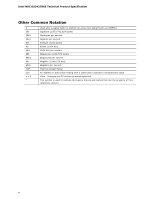
Intel NUC D53427RKE Technical Product Specification Other Common Notation # GB GB/s Gb/s KB Kb kb 048,576 bytes) Megabytes per second Megabit (1,048,576 bits) Megabits per second Thermal Design Power An address or data value ending with a lowercase h indicates a hexadecimal value. Volts. Voltages - Intel DC53427HYE | Technical Product Specification - Page 7
Block Diagram 17 1.2 Online Support 18 1.3 Processor 18 1.4 System Memory 19 1.4.1 Memory Configurations 20 1.5 Intel® QS77 Express Chipset 22 1.5.1 Direct Media Interface (DMI 22 1.5.2 Display Interfaces 22 1.6 Graphics Subsystem 23 1.6.1 Integrated Graphics 23 1.6.2 USB 25 1.6.3 AHCI - Intel DC53427HYE | Technical Product Specification - Page 8
2.6.1 Power Supply Considerations 56 2.6.2 Fan Header Current Capability 57 2.7 Thermal Considerations 57 2.8 Reliability 60 2.9 Environmental 60 3 Overview of BIOS Features 3.1 Introduction 61 3.2 BIOS Flash Memory Organization 62 3.3 System Management BIOS (SMBIOS 62 3.4 Legacy USB Support - Intel DC53427HYE | Technical Product Specification - Page 9
Figure 10 45 11. PCI Express Full-/Half-Mini Card Connector 46 12. Dual-Port Front Panel USB 2.0 Header 48 13. 19 V Internal Power Supply Connector 49 14. Front Panel Header 49 15. States for a One-Color Power LED 50 16. BIOS Setup Configuration Jumper Settings 53 17. Intel MEBX Reset Header - Intel DC53427HYE | Technical Product Specification - Page 10
Intel NUC D53427RKE Technical Product Specification 27. BIOS Error Messages 69 28. Safety Standards 71 29. EMC Regulations 74 30. Regulatory Compliance Marks 77 x - Intel DC53427HYE | Technical Product Specification - Page 11
Processor Memory Chipset Graphics Audio Peripheral Interfaces Expansion Capabilities Intel® Visual BIOS 4.0 inches by 4.0 inches (101.60 millimeters by 101.60 millimeters) • Soldered-down Intel® Core™ i5-3427U processor with up to 17 W TDP ― Integrated graphics ― Integrated memory controller • Two - Intel DC53427HYE | Technical Product Specification - Page 12
of range power supply voltages • Thermal sense to detect out of range thermal values • One processor fan header • Fan sense input used to monitor fan activity • Simple fan speed control • Intel® Active Management Technology (Intel® AMT) 8.0 • Intel® Virtualization (Intel® VT) • Intel® Virtualization - Intel DC53427HYE | Technical Product Specification - Page 13
Product Description 1.1.2 Board Layout (Top) Figure 1 shows the location of the major components on the top-side of Intel NUC Board D53427RKE. Figure 1. Major Board Components (Top) 13 - Intel DC53427HYE | Technical Product Specification - Page 14
Intel NUC D53427RKE Technical Product Specification Table 2 lists the components identified in Figure 1. Table 2. Components Shown in Figure 1 Item from Figure 1 A B Description Standby power LED Battery C Processor fan header D Onboard power button E Power LED F Hard Disk Drive LED G - Intel DC53427HYE | Technical Product Specification - Page 15
Product Description 1.1.3 Board Layout (Bottom) Figure 2 shows the location of the major components on the bottom-side of Intel NUC Board D53427RKE. Figure 2. Major Board Components (Bottom) 15 - Intel DC53427HYE | Technical Product Specification - Page 16
Intel NUC D53427RKE Technical Product Specification Table 3. Components Shown in Figure 2 Item header E Front panel USB 3.0 port F BIOS setup configuration jumper G Front panel header H Intel® Management Engine BIOS Extension (Intel® MEBX) Reset header I DDR3 SO-DIMM 2 socket J DDR3 - Intel DC53427HYE | Technical Product Specification - Page 17
Product Description 1.1.4 Block Diagram Figure 3 is a block diagram of the major functional areas of the board. Figure 3. Block Diagram 17 - Intel DC53427HYE | Technical Product Specification - Page 18
/chipsets.html http://downloadcenter.intel.com http://www.intel.com/support/motherboards/desktop/sb/CS025414.htm http://www.intel.com/support/go/buildit 1.3 Processor The board has a soldered-down Intel Core i5-3427 processor with Integrated Graphics Technology and integrated memory controller - Intel DC53427HYE | Technical Product Specification - Page 19
/512 M x8 16 Note: "DS" refers to double-sided memory modules (containing two rows of SDRAM) and "SS" refers to single-sided memory modules (containing one row of SDRAM). For information about... Tested Memory Refer to: http://support.intel.com/support/motherboards/desktop/sb /CS-025414.htm 19 - Intel DC53427HYE | Technical Product Specification - Page 20
Technology and device width can vary from one channel to the other. If different speed SO-DIMMs are used between channels, the slowest memory timing will be used. For information about... Memory Configuration Examples Refer to: http://www.intel.com/support/motherboards/desktop/sb/cs011965.htm 20 - Intel DC53427HYE | Technical Product Specification - Page 21
Product Description Figure 4 illustrates the memory channel and SO-DIMM configuration. Figure 4. Memory Channel and SO-DIMM Configuration 21 - Intel DC53427HYE | Technical Product Specification - Page 22
, LPC, LAN, and PCI Express interfaces. The Intel QS77 Express Chipset is a centralized controller for the board's I/O paths. For information about The Intel QS77 chipset Resources used by the chipset Refer to http://www.intel.com/products/desktop/chipsets/index.htm Chapter 2 1.5.1 Direct Media - Intel DC53427HYE | Technical Product Specification - Page 23
Integrated Graphics The board supports integrated graphics through Intel FDI. 1.6.1.1 Intel® High Definition (Intel® HD) Graphics The Intel HD graphics controller features the following: • 3D Features DirectX* 10.1 and OpenGL* 3.0 compliant DirectX 11.0 CS4.0 only Shader Model 4.0 • Video - Intel DC53427HYE | Technical Product Specification - Page 24
Intel NUC D53427RKE Technical Product Specification 1.6.1.3.1 Integrated Audio Provided by the HDMI Interface The following audio technologies are supported by the HDMI 1.4a interface directly from the PCH: • AC-3 - Dolby* Digital • Dolby Digital Plus • DTS-HD* • Dolby TrueHD, DTS-HD Master Audio - Intel DC53427HYE | Technical Product Specification - Page 25
, full-speed, and low-speed capable. NOTE Computer systems that have an unshielded cable attached to supports AHCI storage mode via the Intel QS77 Express Chipset. NOTE In order to use AHCI mode, AHCI must be enabled in the BIOS. Microsoft Windows 7 and Windows 8 include the necessary AHCI drivers - Intel DC53427HYE | Technical Product Specification - Page 26
applied via the power supply 5 V STBY rail. NOTE If the battery and AC power fail, date and time values will be reset and the user will be notified during the POST. When the voltage drops below a certain level, the BIOS Setup program settings stored in CMOS RAM (for example, the date and time) might - Intel DC53427HYE | Technical Product Specification - Page 27
management traffic (Sx low power state) • Compliant to IEEE 802.3x flow control support • 802.1p and 802.1q • TCP, IP, and UDP checksum offload (for IPv4 and IPv6) • Full device driver compatibility 1.8.2 LAN Subsystem Software LAN software and drivers are available from Intel's World Wide Web site - Intel DC53427HYE | Technical Product Specification - Page 28
Intel NUC D53427RKE Technical Product Connector LED Locations Table 6 describes the LED states when the board is powered up and the LAN subsystem is operating. Table 6. LAN Connector LED is established. LAN activity is occurring. 10 Mb/s data rate is selected. 100 Mb/s data rate is selected. 1000 - Intel DC53427HYE | Technical Product Specification - Page 29
The hardware monitoring and fan control subsystem is based on a Nuvoton NCT5577D embedded controller, which supports the following: • Processor and system ambient temperature monitoring • Chassis fan speed monitoring • Voltage monitoring of +12 V, +5 V, +3.3 V, Memory Vcc (V_SM), +Vccp, PCH - Intel DC53427HYE | Technical Product Specification - Page 30
Intel NUC D53427RKE Technical Product Specification 1.9.3 Thermal Solution Figure 6 shows the location of the thermal solution and processor fan header. Item A B Description Processor fan header Thermal solution Figure 6. Thermal Solution and Fan Header 30 - Intel DC53427HYE | Technical Product Specification - Page 31
LAN wake capabilities Wake from USB WAKE# signal wake-up support Wake from S5 +5 V Standby Power Indicator LED 1.10.1 ACPI ACPI gives the operating system direct control over the power management and Plug and Play functions of a computer. The use of ACPI with this board requires an operating - Intel DC53427HYE | Technical Product Specification - Page 32
Intel NUC D53427RKE Technical Product Specification 1.10.1.1 System States and Power States Under ACPI, the operating system directs all system and device power state transitions. The operating system puts devices in and out of low-power states based on user preferences and knowledge of how devices - Intel DC53427HYE | Technical Product Specification - Page 33
(S4) in Windows 8. NOTE The use of these wake-up events from an ACPI state requires an operating system that provides full ACPI support. In addition, software, drivers, and peripherals must fully support ACPI wake events. 1.10.2 Hardware Support The board provides several power management hardware - Intel DC53427HYE | Technical Product Specification - Page 34
Intel NUC D53427RKE Technical Product Specification 1.10.2.1 Power Input When resuming from an AC power failure, the computer returns to the power state it was in before power was interrupted (on or off). The computer's response can be set using the Last Power State feature in the BIOS Setup - Intel DC53427HYE | Technical Product Specification - Page 35
LED The standby power indicator LED shows that power is still present even when the computer appears to be off. Figure 7 shows the location of the standby power LED. CAUTION If AC power has been switched off and the standby power indicator is still lit, disconnect the power cord before installing or - Intel DC53427HYE | Technical Product Specification - Page 36
IT organizations to better discover, heal, and protect their networked computing assets. Some of the features of Intel AMT include: • Out-of-band (OOB) system access, to discover assets even while PCs are powered off • Remote trouble-shooting and recovery, which allows remote diagnosis and recovery - Intel DC53427HYE | Technical Product Specification - Page 37
console's own mouse and keyboard NOTE Intel AMT requires the computer system to have an Intel AMT-enabled chipset, network hardware and software, as well as connection with a power source, a corporate network connection, and an Intel AMT-enabled remote management console. Setup requires additional - Intel DC53427HYE | Technical Product Specification - Page 38
computer is disconnected from the network. NOTE No computer system can provide absolute security under all conditions. Intel AT requires the computer system to have an Intel® AT-enabled chipset, BIOS, firmware release, software, and an Intel AT-capable Service Provider/ISV application and service - Intel DC53427HYE | Technical Product Specification - Page 39
businesses with security and productivity capabilities to help keep their PCs up-to-date, protected and running well. Intel SBT is the firmware component of Intel® Small Business Advantage (Intel® SBA) and includes this hardware functionality: • Local Maintenance Timer - Enables applications to - Intel DC53427HYE | Technical Product Specification - Page 40
Intel NUC D53427RKE Technical Product Specification 40 - Intel DC53427HYE | Technical Product Specification - Page 41
space that is allocated for PCI Conventional bus add-in cards, PCI Express configuration space, BIOS (SPI Flash device), and chipset overhead resides above the top of DRAM (total system memory). On a system that has 16 GB of system memory installed, it is not possible to use all of the installed - Intel DC53427HYE | Technical Product Specification - Page 42
Intel NUC D53427RKE Technical Product Specification 2.2 Connectors and Headers CAUTION Only the following only to devices inside the computer's chassis, such as fans and internal peripherals. Do not use these connectors or headers to power devices external to the computer's chassis. A fault in the - Intel DC53427HYE | Technical Product Specification - Page 43
Technical Reference 2.2.1 Back Panel Connectors Figure 9 shows the location of the back panel connectors for the board. Item A B C D E F G Description LAN connector HDMI connector Mini DisplayPort connector #1 Mini DisplayPort connector #2 USB 2.0 port USB 2.0 port 19 V DC input jack Figure 8. - Intel DC53427HYE | Technical Product Specification - Page 44
Intel NUC D53427RKE Technical Product Specification 2.2.2 Connectors and Headers (Bottom) Figure 10 shows the locations of the connectors and headers on the bottom-side of the board. Figure 9. Connectors and Headers (Bottom) 44 - Intel DC53427HYE | Technical Product Specification - Page 45
10. Table 10. Connectors and Headers Shown in Figure 10 Item from Figure 10 Description A PCI Express Full-Mini Card connector B PCI Express Half-Mini Card connector C Front panel dual-port USB 2.0 header D Front panel header E Intel MEBX Reset header F Internal DC power connector - Intel DC53427HYE | Technical Product Specification - Page 46
Intel NUC D53427RKE Technical Product Specification 2.2.2.1 Signal Tables for the Connectors and Headers Table 11. PCI Express Full-/Half-Mini Card Connector Pin Signal Name 1 WAKE# 2 +3.3 V aux 3 Reserved 4 GND 5 Reserved 6 1.5 V 7 CLKREQ# 8 Reserved 9 GND 10 Reserved 11 - Intel DC53427HYE | Technical Product Specification - Page 47
Signal Name (mSATA) NC (Intel AMT) C-Link_CLK* (Intel AMT) C-Link_DAT* (Intel AMT) C-Link_RST* (mSATA) mSATA SEL NOTE The mSATA signals are routed the half-mini card connector. These signals are required to support mSATA modules. NOTE The Intel AMT C-Link signals are routed only to the PCIe half- - Intel DC53427HYE | Technical Product Specification - Page 48
Intel NUC D53427RKE Technical Product Specification Table 12. Dual-Port Front Panel USB 2.0 Header Pin Signal Name Pin Signal Name 1 +5 V DC 2 +5 V DC 3 D− 4 D− 5 D+ 6 D+ 7 Ground 8 Ground 9 KEY (no pin) 10 No Connect 2.2.2.2 Add-in Card Connectors The board has the - Intel DC53427HYE | Technical Product Specification - Page 49
power supply. Table 13. 19 V Internal Power Supply Connector Pin Signal Name 1 Ground 2 +19 V (±10%) For information about Power supply # [In] Reset switch 9 +5V_DC Power Pin Signal Name 2 POWER_LED_MAIN 4 POWER_LED_ALT 6 POWER_SWITCH# 8 GROUND 10 Key Description [Out - Intel DC53427HYE | Technical Product Specification - Page 50
Intel NUC D53427RKE Technical Product Specification Figure 10 an onboard SATA connector. 2.2.2.4.2 Reset Switch Header Pins 5 and is closed, the board resets and runs the POST. 2.2.2.4.3 Power/Sleep LED Header Pins a One-Color Power LED LED State Description Off Power off Blinking Standby - Intel DC53427HYE | Technical Product Specification - Page 51
on or off. (The time requirement is due to internal debounce circuitry on the board.) At least two seconds must pass before the power supply will recognize another on/off signal. 2.2.2.5 Front Panel USB 2.0 Header Figure 12 is a connection diagram for the front panel USB 2.0 header. NOTE • The - Intel DC53427HYE | Technical Product Specification - Page 52
Intel NUC D53427RKE Technical Product Specification 2.3 BIOS Setup Configuration Jumper CAUTION Do not move a jumper with the power on. Always turn off the power and unplug the power cord from the computer before changing a jumper setting. Otherwise, the board could be damaged. Figure 13 shows the - Intel DC53427HYE | Technical Product Specification - Page 53
a jumper (not supplied) will accomplish the following: • Return all Intel ME parameters to their default values. • Reset the Intel MEBX password to the default value (admin). CAUTION Always turn off the power and unplug the power cord from the computer before installing an MEBX reset jumper. The - Intel DC53427HYE | Technical Product Specification - Page 54
Intel NUC D53427RKE Technical Product Specification Figure 13. Intel MEBX Reset Header Table 17. Intel MEBX Reset Header Signals Pin Function 1 PCH_RTCRST_PULLUP 2 Ground 3 No connection 54 - Intel DC53427HYE | Technical Product Specification - Page 55
Technical Reference 2.5 Mechanical Considerations 2.5.1 Form Factor The board is designed to fit into a custom chassis. Figure 14 illustrates the mechanical form factor for the board. Dimensions are given in inches [millimeters]. The outer dimensions are 4.0 inches by 4.0 inches [101.60 millimeters - Intel DC53427HYE | Technical Product Specification - Page 56
19 V DC jack is the primary power input connector of Intel NUC Board D53427RKE. However, the board also provides an internal 1 x 2 power connector that can be used in custom-developed systems that have a custom internal power supply. The internal 1 x 2 power connector is a Molex 5566-2 header which - Intel DC53427HYE | Technical Product Specification - Page 57
for determining the adequacy of any thermal or system design remains solely with the system integrator. Intel makes no warranties or representations that merely following the instructions presented in this document will result in a system with adequate thermal performance. CAUTION Ensure that the - Intel DC53427HYE | Technical Product Specification - Page 58
Intel NUC D53427RKE Technical Product Specification Figure 15 shows the locations of the localized high temperature zones. Item A B Description Processor voltage regulator area Thermal solution Figure 15. Localized High Temperature Zones 58 - Intel DC53427HYE | Technical Product Specification - Page 59
in the system BIOS is a updates Intel QS77 Express Chipset 104 oC For information about Processor datasheets and specification updates Intel® 7 Series Chipset Thermal Mechanical Specifications and Design Guidelines Refer to Section 1.2, page 18 http://www.intel.com/Products/Desktop/ Chipsets - Intel DC53427HYE | Technical Product Specification - Page 60
Intel NUC D53427RKE Technical Product Specification 2.8 Reliability The Mean Time Between Failures (MTBF) prediction is calculated using component and subassembly random failure rates. The calculation is based on the Telcordia SR-332 Issue 2, Method I, Case 3, 55 ºC ambient. The MTBF prediction is - Intel DC53427HYE | Technical Product Specification - Page 61
. The Visual BIOS Setup program can be used to view and change the BIOS settings for the computer. The BIOS Setup program is accessed by pressing the key after the Power-On Self-Test (POST) memory test begins and before the operating system boot begins. Figure 16. Intel Visual BIOS Home Screen - Intel DC53427HYE | Technical Product Specification - Page 62
Organization The Serial Peripheral Interface Flash Memory (SPI Flash) includes a 128 Mb (16000 KB) flash memory device. 3.3 System Management BIOS (SMBIOS) SMBIOS is a Desktop Management Interface (DMI) compliant method for managing computers in a managed network. The main component of SMBIOS is - Intel DC53427HYE | Technical Product Specification - Page 63
an incompatible BIOS. NOTE Review the instructions distributed with the upgrade utility before attempting a BIOS update. For information about BIOS update utilities Refer to http://support.intel.com/support/motherboards/desktop/sb /CS-022312.htm 3.5.1 Language Support The BIOS Setup program - Intel DC53427HYE | Technical Product Specification - Page 64
is bigger than 1.4 MB size limit) NOTE Supported file systems for BIOS recovery: • NTFS (sparse, compressed, or encrypted files are not supported) • FAT32 • FAT16 • FAT12 • ISO 9660 For information about BIOS recovery Refer to http://www.intel.com/support/motherboards/desktop/sb/cs-023360.htm 64 - Intel DC53427HYE | Technical Product Specification - Page 65
the BIOS Setup program, the user can choose to boot from a hard drive, optical drive, removable drive, or the network. The default setting is for the optical drive to be the first boot device, the hard drive second, removable drive third, and the network fourth. 3.7.1 Network Boot The network can - Intel DC53427HYE | Technical Product Specification - Page 66
, the system will halt with the message: Hard Disk Drive Password Entry Error A manual power cycle will be required to resume system operation. NOTE As implemented on D53427RKE, Hard Disk Drive Password Security is only supported on SATA port 0. The passwords are stored on the hard disk drive so if - Intel DC53427HYE | Technical Product Specification - Page 67
includes security features that restrict access to the BIOS Setup program and who can boot the computer. A supervisor password and a user password can be set for the BIOS Setup program and for booting the computer, with the following restrictions: • The supervisor password gives unrestricted access - Intel DC53427HYE | Technical Product Specification - Page 68
Intel NUC D53427RKE Technical Product Specification 68 - Intel DC53427HYE | Technical Product Specification - Page 69
LED Blink Codes Whenever a recoverable error occurs during POST, the BIOS causes the board's front panel power LED to blink an error message describing the problem (see Table 26). Table 26. Front-panel Power LED Blink Codes Type Pattern BIOS update in progress Video error (Note) Off when the - Intel DC53427HYE | Technical Product Specification - Page 70
Intel NUC D53427RKE Technical Product Specification 70 - Intel DC53427HYE | Technical Product Specification - Page 71
Declaration of Conformity statement • Product Ecology statements • Electromagnetic Compatibility (EMC) standards • Product certification markings 5.1.1 Safety Standards Intel NUC Board D53427RKE complies with the safety standards stated in Table 28 when correctly installed in a compatible host - Intel DC53427HYE | Technical Product Specification - Page 72
D53427RKE Technical Product Specification 5.1.2 European Union Declaration of Conformity Statement We, Intel Corporation, declare under our sole responsibility that the products Intel® NUC Board D53427RKE is in conformity with all applicable essential requirements necessary for CE marking, following - Intel DC53427HYE | Technical Product Specification - Page 73
Regulatory Compliance and Battery Disposal Information Portuguese Este produto cumpre com as normas da Diretiva Européia 2004/108/EC, 2006/95/EC & 2002/95/EC. Español Este producto cumple con las normas del Directivo Europeo 2004/108/EC, 2006/95/EC & 2002/95/EC. Slovensky Tento produkt je v súlade s - Intel DC53427HYE | Technical Product Specification - Page 74
5.1.4 EMC Regulations Intel NUC Board D53427RKE complies with . (International) VCCI V-3, V-4 Voluntary Control for Interference by Information Technology Equipment. not installed and used in accordance with the instructions, may cause harmful interference to radio communications. However - Intel DC53427HYE | Technical Product Specification - Page 75
approved by Intel Corporation could void Control Council for Interference from Information Technology Equipment (VCCI). If this is used near a radio or television receiver in a domestic environment, it may cause radio interference. Install and use the equipment according to the instruction manual - Intel DC53427HYE | Technical Product Specification - Page 76
Intel NUC Board D53427RKE allows for a compliant system built to meet the following program requirements, including appropriate selection of an efficient power supply chipset, power supply, HDD, graphics controller, memory, etc. to meet the specification. For more information on ENERGY STAR Computers - Intel DC53427HYE | Technical Product Specification - Page 77
(Board Level) Intel NUC Board D53427RKE has mark. Includes adjacent UL file number for Intel NUC Boards: E210882. Mark FCC Declaration of Intel supplier code number, N-232. Japan VCCI (Voluntary Control Council an example of the symbol used on Intel NUC Boards and associated collateral. The color of - Intel DC53427HYE | Technical Product Specification - Page 78
Intel NUC D53427RKE Technical Product Specification 5.2 Battery Disposal Information CAUTION Risk of explosion if the battery is replaced with an incorrect type. Batteries should be recycled where - Intel DC53427HYE | Technical Product Specification - Page 79
Regulatory Compliance and Battery Disposal Information PRECAUCIÓN Existe peligro de explosión si la pila no se cambia de forma adecuada. Utilice solamente pilas iguales o del mismo tipo que las recomendadas por el fabricante del equipo. Para deshacerse de las pilas usadas, siga igualmente las - Intel DC53427HYE | Technical Product Specification - Page 80
Intel NUC D53427RKE Technical Product Specification AWAS Risiko letupan wujud jika bateri digantikan dengan jenis yang tidak betul. Bateri sepatutnya dikitar semula jika boleh. Pelupusan bateri terpakai - Intel DC53427HYE | Technical Product Specification - Page 81
Regulatory Compliance and Battery Disposal Information 81 - Intel DC53427HYE | Technical Product Specification - Page 82
Intel NUC D53427RKE Technical Product Specification 82
-
 1
1 -
 2
2 -
 3
3 -
 4
4 -
 5
5 -
 6
6 -
 7
7 -
8
-
9
-
10
-
11
-
12
-
13
-
14
-
15
-
16
-
17
-
18
-
19
-
20
-
21
-
22
-
23
-
24
-
25
-
26
-
27
-
28
-
29
-
30
-
31
-
32
-
33
-
34
-
35
-
36
-
37
-
38
-
39
-
40
-
41
-
42
-
43
-
44
-
45
-
46
-
47
-
48
-
49
-
50
-
51
-
52
-
53
-
54
-
55
-
56
-
57
-
58
-
59
-
60
-
61
-
62
-
63
-
64
-
65
-
66
-
67
-
68
-
69
-
70
-
71
-
72
-
73
-
74
-
75
-
76
-
77
-
78
-
79
-
80
-
81
-
82
 |
 |

Intel® NUC
Board D53427RKE
Technical Product Specification
May 2013
Order Number:
G97389-001
The Intel NUC Board D53427RKE may contain design defects or errors known as errata that may cause the product to deviate from published specifications.
Current characterized errata are documented in the Intel NUC Board D53427RKE Specification Update.