Intel DG31GL Product Guide
Intel DG31GL - Desktop Board Essential Series Motherboard Manual
 |
UPC - 735858200929
View all Intel DG31GL manuals
Add to My Manuals
Save this manual to your list of manuals |
Intel DG31GL manual content summary:
- Intel DG31GL | Product Guide - Page 1
Intel® Desktop Board DG31GL Product Guide Order Number: E35043-001 - Intel DG31GL | Product Guide - Page 2
Intel® Desktop Board DG31GL Product Guide Date March 2008 If an FCC declaration of conformity marking is present on the board the instructions, may INTEL® PRODUCTS. NO LICENSE, EXPRESS Intel may make changes to specifications and product descriptions at any time, without notice. Desktop Board DG31GL - Intel DG31GL | Product Guide - Page 3
Installing and Replacing Desktop Board Components: instructions on how to install the Desktop Board and other hardware components 3 Updating the BIOS: instructions on how to update the BIOS A Error Messages and Indicators: information about BIOS error messages and beep codes B Regulatory Compliance - Intel DG31GL | Product Guide - Page 4
Intel Desktop Board DG31GL Product Guide Conventions The following conventions are used in this manual: CAUTION Cautions warn the user about how to prevent damage to hardware or loss of data. NOTE Notes call attention to important information. Terminology The - Intel DG31GL | Product Guide - Page 5
1 Desktop Board Features Desktop Board Components 11 Processor ...13 Main Memory...13 Intel® G31 Express Chipset 14 Audio Subsystem 15 Legacy Input/Output (I/O) Controller 15 LAN Subsystem 15 Hi-Speed USB 2.0 Support 16 Enhanced IDE Interface 17 Serial ATA...17 Expandability...17 BIOS ...17 - Intel DG31GL | Product Guide - Page 6
47 3 Updating the BIOS Updating the BIOS with the Intel® Express BIOS Update Utility 53 Updating the BIOS with the ISO Image BIOS Update File or the Iflash Memory Update Utility 54 Obtaining the BIOS Update File 54 Updating the BIOS with the ISO Image BIOS Update File 54 Updating the BIOS with - Intel DG31GL | Product Guide - Page 7
of the BIOS Configuration Jumper Block 45 24. Removing the Battery 51 25. Desktop Board DG31GL China RoHS Material Self Declaration Table 67 Tables 1. Feature Summary 9 2. Desktop Board DG31GL Components 12 3. LAN Connector LEDs 16 4. Front Panel Intel High Definition Audio Header Signal - Intel DG31GL | Product Guide - Page 8
Intel Desktop Board DG31GL Product Guide viii - Intel DG31GL | Product Guide - Page 9
) • Intel G31 Express Chipset Graphics and Memory Controller Hub (GMCH) Intel® GMA 3100 • 4-channel (two independent 2-channel audio streams) onboard audio subsystem, featuring: ― Intel® High Definition Audio ― Support for AC'97 audio ― RealTek*ALC268-GR audio codec ― Onboard S/PDIF connector LAN - Intel DG31GL | Product Guide - Page 10
Microsoft Windows XP Professional • Microsoft Windows XP Professional x64 Edition • Microsoft Windows XP Home For more information about Desktop Board DG31GL, including the Technical Product Specification (TPS), BIOS updates, and device drivers, go to http://support.intel.com/support/motherboards - Intel DG31GL | Product Guide - Page 11
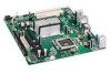
Desktop Board Features Desktop Board Components Figure 1 shows the approximate location of the major components on Desktop Board DG31GL. Figure 1. Desktop Board DG31GL Components 11 - Intel DG31GL | Product Guide - Page 12
2.0 headers (2) Speaker Front panel audio header For more information go to the following locations: • Supported processors http://www.intel.com/go/findCPU • Audio software and utilities http://www.intel.com/design/motherbd • LAN software and drivers http://www.intel.com/design/motherbd 12 - Intel DG31GL | Product Guide - Page 13
for more information: • Instructions on installing or upgrading the processor, page 27 in Chapter 2 • Supported processors for Desktop Board DG31GL, http://www.intel.com/go/findCPU Main Memory NOTE To be fully compliant with all applicable Intel ® SDRAM memory specifications, the board should be - Intel DG31GL | Product Guide - Page 14
Intel Desktop Board DG31GL Product Guide Intel® G31 Express Chipset The Intel G31 Express Chipset consists of the following devices: • Intel G31 Express Chipset Graphics and Memory Controller Hub (GMCH) with Direct Media Interface (DMI) • Intel 82801G I/O Controller Hub (ICH7) with DMI The GMCH - Intel DG31GL | Product Guide - Page 15
• RJ-45 LAN connector with integrated status LEDs The subsystem features: • CSMA/CD protocol engine • LAN connect interface between ICH7 and the LAN controller • PCI bus power management For information about LAN software and drivers, go to http://support.intel.com/support/motherboards/desktop. 15 - Intel DG31GL | Product Guide - Page 16
Intel Desktop Board DG31GL Product Guide Two LEDs are built into the RJ-45 LAN connector located on the back panel (see Figure 2). These LEDs indicate the status of the LAN. Figure 2. LAN Status LEDs Table 3 describes the LED states when the board is powered up and the LAN subsystem is operating. - Intel DG31GL | Product Guide - Page 17
CD-ROM drives) • Older PIO Mode devices • Ultra DMA-33 and ATA-66/100 protocols Serial ATA The Desktop Board supports two Serial ATA channels (3.0 Gb/s) via ICH7, connecting one device per channel. Expandability For system expansion, the Desktop Board provides two PCI bus connectors. BIOS The BIOS - Intel DG31GL | Product Guide - Page 18
Intel Desktop Board DG31GL Product Guide Security Passwords The BIOS includes security features that restrict whether the BIOS Setup program can be accessed and who can boot the computer. A supervisor password and a user password can be set for the BIOS Setup and for booting the computer, with the - Intel DG31GL | Product Guide - Page 19
Board requires an operating system that provides full ACPI support. Hardware Support Power State feature in the BIOS Setup program's Boot menu. The Desktop Board has two power connectors. Board has a 4-pin processor fan header and a 3-pin chassis fan header. LAN Wake Capabilities CAUTION For LAN - Intel DG31GL | Product Guide - Page 20
Intel Desktop Board DG31GL Product Guide Instantly Available PC Technology CAUTIONS For Instantly Available last known awake state. The Desktop Board supports the PCI Bus Power Management Interface Specification. Add-in cards that support this specification can participate in power management and - Intel DG31GL | Product Guide - Page 21
of the Standby Power Indicator For information on standby current requirements for the Desktop Board, refer to the Technical Product Specification by going to http://support.intel.com/support/motherboards/desktop/, finding the product, and clicking on the Technical Documents tab. Wake from USB - Intel DG31GL | Product Guide - Page 22
Intel Desktop Board DG31GL Product Guide PME# Signal Wake-up Support When the PME# signal on the PCI bus is asserted, the computer wakes from an ACPI S3, S4, or S5 state. ENERGY STAR* Capable In 2007, the US Department of Energy and - Intel DG31GL | Product Guide - Page 23
memory • Connect the diskette drive cable • Connect the IDE and Serial ATA cables • Connect to the internal headers and connectors • Connect to the audio system • Connect chassis fan and power supply cables • Set the BIOS damage. Some circuitry on the board can continue to operate even though - Intel DG31GL | Product Guide - Page 24
Intel Desktop Board DG31GL Product Guide Installation Precautions When you install and test the Intel Desktop Board, observe all warnings and cautions in the installation instructions all warnings and cautions that instruct you to refer computer servicing to qualified technical personnel. Prevent - Intel DG31GL | Product Guide - Page 25
Components Installing the I/O Shield The Desktop Board comes with an I/O shield. When installed in the chassis and promotes correct airflow within the chassis. Install the I/O shield before installing the Desktop Board in the chassis. Place the shield inside the chassis as shown in Figure 4. Press - Intel DG31GL | Product Guide - Page 26
Intel Desktop Board DG31GL Product Guide Installing and Removing the Desktop Board CAUTION Only qualified technical manual for instructions on installing and removing the Desktop Board. Figure 5 shows the location of the mounting screw holes for Desktop Board DG31GL. Figure 5. Desktop Board DG31GL - Intel DG31GL | Product Guide - Page 27
standby power LED should not be lit (see Figure 3 on page 21). Failure to do so could damage the processor and the board. To install a processor, follow these instructions: 1. Observe the precautions in "Before You Begin" on page 23. 2. Open the socket lever by pushing the lever down and away from - Intel DG31GL | Product Guide - Page 28
Intel Desktop Board DG31GL Product Guide 3. Lift the load plate (Figure 7, A). Do not touch the socket contacts (Figure 7, B). Figure 7. Lift the Load Plate 4. Remove the plastic protective socket cover from the - Intel DG31GL | Product Guide - Page 29
Installing and Replacing Desktop Board Components 5. Remove the processor from the protective processor cover. Hold the processor only at the edges, being careful not to touch the bottom of the - Intel DG31GL | Product Guide - Page 30
Intel Desktop Board DG31GL Product Guide 7. Pressing down on the load plate (Figure 11, A), close and engage the socket lever (Figure 11, B). Figure 11. Close the Load Plate Installing the Processor Fan Heat Sink Desktop Board DG31GL has mounting holes for a processor fan heat sink. For instructions - Intel DG31GL | Product Guide - Page 31
Installing and Replacing Desktop Board Components Connecting the Processor Fan Heat Sink Cable Connect the processor fan heat sink cable to the 4-pin processor fan header (see Figure 12). A fan - Intel DG31GL | Product Guide - Page 32
Intel Desktop Board DG31GL Product Guide Removing the Processor For instructions on how to remove the processor fan heat sink and processor, refer to the processor installation manual. Installing and Removing Memory NOTE To be fully compliant with all applicable Intel SDRAM memory specifications, - Intel DG31GL | Product Guide - Page 33
Installing and Replacing Desktop Board Components Installing DIMMs To make sure you have the correct DIMM, place it on the illustration of the DDR2 DIMM in Figure 14. All the notches should match with the DDR2 DIMM. Figure 14. Use DDR2 DIMMs 33 - Intel DG31GL | Product Guide - Page 34
Intel Desktop Board DG31GL Product Guide To install a DIMM, follow these steps: 1. Observe the precautions in "Before You Begin" on page 23. 2. Turn off all peripheral devices connected to the computer. - Intel DG31GL | Product Guide - Page 35
Installing and Replacing Desktop Board Components Removing DIMMs To remove a DIMM, follow these steps: Cable The diskette drive cable can be used to connect a single diskette drive to the Desktop Board. For correct function of the cable: 1. Observe the precautions in "Before You Begin" on page - Intel DG31GL | Product Guide - Page 36
Intel Desktop Board DG31GL Product Guide Figure 16. Connecting the Diskette Drive Cable Connecting the IDE Cable The IDE cable can be used to connect two IDE drives to the Desktop Board. The cable supports the ATA-66/100 transfer protocol. Figure 17 shows the correct installation of the cable. NOTES - Intel DG31GL | Product Guide - Page 37
Installing and Replacing Desktop Board Components Figure 17. Connecting the IDE Cable 37 - Intel DG31GL | Product Guide - Page 38
Intel Desktop Board DG31GL Product Guide Connecting the Serial ATA (SATA) Cables SATA cables support the Serial ATA protocol. Each cable can be used to connect a single internal SATA drive to the Desktop Board. For correct cable function: 1. Observe the precautions in "Before You Begin" on page 23. - Intel DG31GL | Product Guide - Page 39
You Begin" on page 23. Figure 19 shows the location of the internal headers and connectors for Desktop Board DG31GL. Item Description A Front panel audio B S/PDIF C Serial port D Alternate front panel power LED E Front panel F USB 2.0 (2) Figure 19. Internal Headers and Connectors 39 - Intel DG31GL | Product Guide - Page 40
Intel Desktop Board DG31GL Product Guide Connecting to the Front Panel Audio Header Figure 19, A on page 39 shows the location of the front panel audio header. Table 4 shows the pin assignments for the front panel audio header. Table 4. Front Panel Intel High Definition Audio Header Signal Names - Intel DG31GL | Product Guide - Page 41
Installing and Replacing Desktop Board Components Connecting to the Alternate Front Panel Power LED Header Figure 19, D on page 39 shows the location of the alternate front panel power LED - Intel DG31GL | Product Guide - Page 42
Intel Desktop Board DG31GL Product Guide Connecting to the USB 2.0 Headers Before connecting to the USB 2.0 to the Audio System After installing the audio driver from the Intel Express Installer CD-ROM, the multichannel audio feature can be enabled. Figure 20 shows the back panel audio connectors. - Intel DG31GL | Product Guide - Page 43
Installing and Replacing Desktop Board Components NOTE The back panel line out connector is designed to power either headphones or amplified speakers only. Poor audio quality may occur if passive (non-amplified) speakers are connected to this output. Connecting Chassis Fan and Power Supply Cables - Intel DG31GL | Product Guide - Page 44
Intel Desktop Board DG31GL Product Guide Connecting Supply Power Cables CAUTION Failure to use an appropriate power supply and/or not connecting the 12 V (2 x 2 pin) power connector to the Desktop Board may result in damage to the board or the system may not function properly. The 2 x 12 pin main - Intel DG31GL | Product Guide - Page 45
(1-2) Description The BIOS uses the current configuration and passwords for booting. Configure (2-3) Recovery (None) After the Power-On Self-Test (POST) runs, the BIOS displays the Maintenance Menu. Use this menu to clear passwords. The BIOS recovers data in the event of a failed BIOS update. 45 - Intel DG31GL | Product Guide - Page 46
Intel Desktop Board DG31GL Product Guide Clearing Passwords This procedure assumes that the board is installed in the computer starts the Setup program. Setup displays the Maintenance menu. 8. Use the arrow keys to select Clear Passwords. Press and Setup displays a pop-up screen requesting - Intel DG31GL | Product Guide - Page 47
Replacing Desktop Board Components Replacing the Battery A coin-cell battery (CR2032) powers the real-time clock and CMOS memory. When the ºC with 3.3 VSB applied. When the voltage drops below a certain level, the BIOS Setup program settings stored in CMOS RAM (for example, the date and time) might - Intel DG31GL | Product Guide - Page 48
Intel Desktop Board DG31GL Product Guide VORSICHT Bei falschem Einsetzen einer neuen Batterie besteht Explosionsgefahr. Die Batterie darf nur durch denselben oder einen entsprechenden, vom Hersteller empfohlenen Batterietyp ersetzt werden. Entsorgen - Intel DG31GL | Product Guide - Page 49
Installing and Replacing Desktop Board Components VIGYÁZAT Ha a telepet nem a megfelelő típusú telepre cseréli, az felrobbanhat. A telepeket lehetőség szerint újra kell hasznosítani. A használt telepeket a helyi környezetvé - Intel DG31GL | Product Guide - Page 50
Intel Desktop Board DG31GL Product Guide UYARI Yanlış türde pil takıldığında patlama riski vardır. Piller mümkün olduğunda geri dönüştürülmelidir. Kullanılmış piller, yerel çevre yasalarına uygun olarak atılmalıdır. O 50 - Intel DG31GL | Product Guide - Page 51
power source (wall outlet or power adapter). 3. Remove the computer cover. 4. Locate the battery on the board (see Figure 24). 5. With a medium flat-bladed screwdriver, gently pry the battery free from its connector. Note the orientation of the "+" and "-" on the battery. 6. Install the new battery - Intel DG31GL | Product Guide - Page 52
Intel Desktop Board DG31GL Product Guide 52 - Intel DG31GL | Product Guide - Page 53
update the BIOS with the Intel Express BIOS Update utility: 1. Go to the Intel World Wide Web site at http://support.intel.com/support/motherboards/desktop/. 2. Navigate to the DG31GL page, click "[view] Latest BIOS updates," and select the Express BIOS Update utility file. 3. Download the file to - Intel DG31GL | Product Guide - Page 54
Intel Desktop Board DG31GL Product Guide Updating the BIOS with the ISO Image BIOS Update File or the Iflash Memory Update Utility You can use the information in this section to update the BIOS using either the Iflash Memory Update Utility or the ISO Image BIOS update file. Obtaining the BIOS Update - Intel DG31GL | Product Guide - Page 55
The Iflash BIOS update files can also be extracted locally to your hard drive and copied to a bootable USB flash drive or other bootable USB media. The Iflash Memory update utility allows you to: • Update the BIOS in flash memory • Update the language section of the BIOS NOTE Review the instructions - Intel DG31GL | Product Guide - Page 56
damaged. Due to BIOS size and recovery requirements, a CD-R with the .BIO file in the root directory will be required. For more information about updating the Intel Desktop Board BIOS or recovering from a BIOS update failure, go to http://support.intel.com/support/motherboards/desktop/sb/CS-022312 - Intel DG31GL | Product Guide - Page 57
Desktop Board DG31GL reports POST errors in two ways: • By sounding a beep code • By displaying an error message on the monitor BIOS Beep Codes The BIOS also issues a beep code (one long tone followed by two short tones) during POST if the video configuration fails (a faulty video card or no card - Intel DG31GL | Product Guide - Page 58
Intel Desktop Board DG31GL Product Guide 58 - Intel DG31GL | Product Guide - Page 59
(EMC) regulations • Product certifications Safety Standards Desktop Board DG31GL complies with the safety standards stated in Table 13 ) Place Battery Marking There is insufficient space on this Desktop Board to provide instructions for replacing and disposing of the Lithium ion coin cell battery - Intel DG31GL | Product Guide - Page 60
Intel Desktop Board DG31GL Product Guide European Union Declaration of Conformity Statement We, Intel Corporation, declare under our sole responsibility that the product Intel® Desktop Board DG31GL is in conformity with all applicable essential requirements necessary for CE marking, following the - Intel DG31GL | Product Guide - Page 61
consult http://www.intel.com/intel/other/ehs/product_ecology for the details of this program, including the scope of covered products, available locations, shipping instructions, terms and conditions, etc Intel Product Recycling Program http://www.intel.com/intel/other/ehs/product_ecology 61 - Intel DG31GL | Product Guide - Page 62
Intel Desktop Board DG31GL Product Guide Deutsch Als Teil von Intels Engagement für den Umweltschutz hat das Unternehmen das Intel Produkt-Recyclingprogramm implementiert, das Einzelhandelskunden von Intel , les instructions d'expédition, les conditions générales, etc. http://www.intel.com/in - Intel DG31GL | Product Guide - Page 63
produtos cobertos, os locais disponíveis, as instruções de envio, os termos e condições, etc. Russian Intel Intel (Product Recycling Program Intel http://www.intel.com/intel/other/ehs/product_ecology Türkçe Intel, çevre sorumluluğuna bağımlılığının bir parçası olarak, perakende tüketicilerin - Intel DG31GL | Product Guide - Page 64
Intel Desktop Board DG31GL Product Guide Lead-free 2LI/Pb-free 2LI Board The electronics industry is transitioning to European Union (EU) Restriction of Hazardous Substances (RoHS)-compliant products. The RoHS legislation restricts the use of six materials. - Intel DG31GL | Product Guide - Page 65
) The maximum concentrations allowed are 0.1% or 1000 ppm (except for cadmium, which is limited to 0.01% or 100 ppm) by weight of homogeneous material. Desktop Board DG31GL complies with these restrictions. 65 - Intel DG31GL | Product Guide - Page 66
Intel Desktop Board DG31GL Product Guide China RoHS "China RoHS" is the term used by industry However, the China RoHS regulation requires specific product marking and a selfdeclaration of the controlled substances contained in each product. Desktop Board DG31GL is a China RoHS-compliant product. - Intel DG31GL | Product Guide - Page 67
Regulatory Compliance The China MII stipulates that a material Self Declaration Table (SDT) must be included in a product's user documentation. The SDT for Desktop Board DG31GL is shown in Figure 25. Figure 25. Desktop Board DG31GL China RoHS Material Self Declaration Table 67 - Intel DG31GL | Product Guide - Page 68
Intel Desktop Board DG31GL Product Guide EMC Regulations Desktop Board DG31GL complies with the EMC regulations stated in Table 16 when correctly installed in a compatible host environment, it may cause radio interference. Install and use the equipment according to the instruction manual. 68 - Intel DG31GL | Product Guide - Page 69
, as applicable, have passed Class B EMC testing and are marked accordingly. Pay close attention to the following when reading the installation instructions for the host chassis, power supply, and other modules: • Product certifications or lack of certifications • External I/O cable shielding and - Intel DG31GL | Product Guide - Page 70
Product Guide Product Certifications Board-Level Certification Markings Desktop Board DG31GL has the product certification markings shown in Table 17. Table 17. Product Certification Markings Description UL joint US/Canada Recognized Component mark. Includes adjacent UL file number for Intel - Intel DG31GL | Product Guide - Page 71
Canada A nationally recognized certification mark such as CSA or cUL signifies compliance with safety requirements. The Industry Canada statement at the front of this product guide demonstrates compliance with Canadian EMC regulations. 71 - Intel DG31GL | Product Guide - Page 72
Intel Desktop Board DG31GL Product Guide 72
-
 1
1 -
 2
2 -
 3
3 -
 4
4 -
 5
5 -
 6
6 -
 7
7 -
8
-
9
-
10
-
11
-
12
-
13
-
14
-
15
-
16
-
17
-
18
-
19
-
20
-
21
-
22
-
23
-
24
-
25
-
26
-
27
-
28
-
29
-
30
-
31
-
32
-
33
-
34
-
35
-
36
-
37
-
38
-
39
-
40
-
41
-
42
-
43
-
44
-
45
-
46
-
47
-
48
-
49
-
50
-
51
-
52
-
53
-
54
-
55
-
56
-
57
-
58
-
59
-
60
-
61
-
62
-
63
-
64
-
65
-
66
-
67
-
68
-
69
-
70
-
71
-
72
 |
 |

Intel
®
Desktop Board DG31GL
Product Guide
Order Number:
E3504
3
-001