Intel DG31PR Product Guide
Intel DG31PR - Desktop Board Classic Series Motherboard Manual
 |
UPC - 735858195331
View all Intel DG31PR manuals
Add to My Manuals
Save this manual to your list of manuals |
Intel DG31PR manual content summary:
- Intel DG31PR | Product Guide - Page 1
Intel® Desktop Board DG31PR Product Guide Order Number: D99182-001 - Intel DG31PR | Product Guide - Page 2
the instructions, Intel may make changes to specifications and product descriptions at any time, without notice. Desktop Board DG31PR Intel literature, may be obtained from Intel Corporation by going to the World Wide Web site at: http://www.intel.com/ or by calling 1-800-548-4725. Intel, the Intel - Intel DG31PR | Product Guide - Page 3
of product features 2 Installing and Replacing Desktop Board Components: instructions on how to install the Desktop Board and other hardware components 3 Updating the BIOS: instructions on how to update the BIOS A Error Messages and Indicators: information about BIOS error messages and beep codes - Intel DG31PR | Product Guide - Page 4
Megahertz (one million hertz) Box Contents • Intel Desktop Board DG31PR • I/O shield • Diskette drive cable • ATA-66/100 cable • Two locking Serial ATA (SATA) cables • Quick Reference guide • Configuration and battery caution statement labels • Intel® Express Installer Driver and Software CD-ROM - Intel DG31PR | Product Guide - Page 5
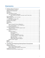
Contents 1 Desktop Board Features Supported Operating Systems 10 Desktop Board Components 11 Processor ...13 Main Memory...13 Intel® G31 Express Chipset 14 Intel® G33 Graphics Subsystem 15 Intel® GMA 3100 Graphics Controller (Intel® GMA 3100 15 Audio Subsystem 16 Legacy Input/Output (I/O) - Intel DG31PR | Product Guide - Page 6
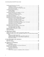
Setting the BIOS Configuration Jumper 52 Clearing Passwords 53 Replacing the Battery 54 3 Updating the BIOS Updating the BIOS with the Intel® Express BIOS Update Utility 59 Updating the BIOS with the ISO Image BIOS Update File or the Iflash Memory Update Utility ...60 Obtaining the BIOS Update - Intel DG31PR | Product Guide - Page 7
Power Supply Cables 51 25. Location of the BIOS Configuration Jumper Block 52 26. Removing the Battery 58 Tables 1. Feature Summary 9 2. Desktop Board DG31PR Components 12 3. LAN Connector LEDs 18 4. Front Panel Intel High Definition Audio Header Signal Names 46 5. S/PDIF Connector 46 - Intel DG31PR | Product Guide - Page 8
Intel Desktop Board DG31PR Product Guide viii - Intel DG31PR | Product Guide - Page 9
1 Desktop Board Features This chapter briefly describes the features of Intel® Desktop Board DG31PR. Table 1 summarizes the major features of the Desktop Board. Table 1. Feature Summary Form Factor Processor Main Memory Chipset Graphics Audio LAN Support Expansion Capabilities Peripheral - Intel DG31PR | Product Guide - Page 10
monitor fan speed Related Links: For more information about Desktop Board DG31PR, including the Technical Product Specification (TPS), BIOS updates, and device drivers, go to: http://support.intel.com/support/motherboards/desktop/ Supported Operating Systems The Desktop Board supports the following - Intel DG31PR | Product Guide - Page 11
Desktop Board Features Desktop Board Components Figure 1 shows the approximate location of the major components on Desktop Board DG31PR. Figure 1. Desktop Board DG31PR Components 11 - Intel DG31PR | Product Guide - Page 12
Intel Desktop Board DG31PR Product Guide Table 2. Desktop Board DG31PR Components Label A B C D E F G H I J K L M N O P Q R S T U V W X Y Z Description PCI bus connector 2 PCI bus connector 1 Battery panel power LED header BIOS configuration jumper block High-speed USB 2.0 headers Speaker Front - Intel DG31PR | Product Guide - Page 13
more information about: • Instructions on installing or upgrading the processor, page 31 in Chapter 2 • Supported processors for Desktop Board DG31PR, http://www.intel.com/go/findCPU Main Memory NOTE To be fully compliant with all applicable Intel ® SDRAM memory specifications, the board should be - Intel DG31PR | Product Guide - Page 14
Intel Desktop Board DG31PR Product Guide • Support for: ⎯ Unbuffered, non-registered single or double-sided DIMMs ⎯ Non-ECC DDR2 memory ⎯ 1.8 V DIMMs only • DIMM Type and Timings listed below: Type Timing DDR2-800 5-5-5 or 6-6-6 only DDR2-667 5-5-5 only • Serial Presence Detect (SPD) - Intel DG31PR | Product Guide - Page 15
Desktop Board Features Intel® G33 Graphics Subsystem The Intel G31 Express Chipset contains two separate, mutually exclusive graphics options. Either the integrated Intel® Graphics Media Accelerator 3100 (Intel® GMA 3100) graphics controller is used or a PCI Express x16 add-in card can be used. When - Intel DG31PR | Product Guide - Page 16
(using the back panel audio connectors) and stereo (using the Intel High Definition front panel audio header) Related Links: Go to the following link or pages for more information about: • Audio drivers and utilities http://support.intel.com/support/motherboards/desktop/ • The location of the back - Intel DG31PR | Product Guide - Page 17
status LEDs The subsystem features: • CSMA/CD protocol engine • LAN connect interface between ICH7 and the LAN controller • PCI bus power management Related Links: Go to the following link for information about LAN software and drivers: http://support.intel.com/support/motherboards/desktop RJ-45 LAN - Intel DG31PR | Product Guide - Page 18
Intel Desktop Board DG31PR Product Guide Table 3 describes the LED states when the board Speed USB 2.0 Support The Desktop Board supports up to eight USB 2.0 ports (four ports routed to the back panel and four ports routed to two internal headers) via the ICH7. USB 2.0 ports are backward compatible - Intel DG31PR | Product Guide - Page 19
Desktop Board Features Expandability For system expansion, the Desktop Board provides the following expansion slots: • One PCI Express x1 connector • One PCI Express x16 connector • Two PCI bus connectors BIOS The BIOS provides the Power-On Self-Test (POST), the BIOS Setup program, the PCI/PCI - Intel DG31PR | Product Guide - Page 20
. Related Links: For instructions on resetting the password, see Clearing Passwords on page 53. Hardware Management Features The hardware management features of Desktop Board DG31PR enable the board to be compatible with the Wired for Management (WfM) specification. The board has several hardware - Intel DG31PR | Product Guide - Page 21
fan speed or switch the fans off as needed Chassis Intrusion The board supports a chassis security feature that detects if the chassis cover has been removed. The security feature uses a mechanical switch on the chassis that can be connected to the chassis intrusion header on the Desktop Board. See - Intel DG31PR | Product Guide - Page 22
Intel Desktop Board DG31PR Product Guide Hardware Support Power Connectors ATX12V-compliant power supplies can on or off). The computer's response can be set by using the Last Power State feature in the BIOS Setup program's Boot menu. The Desktop Board has two power connectors. See Figure 24 on page - Intel DG31PR | Product Guide - Page 23
-up device or event, the computer quickly returns to its last known awake state. The Desktop Board supports the PCI Bus Power Management Interface Specification. Add-in cards that support this specification can participate in power management and can be used to wake the computer. +5 V Standby Power - Intel DG31PR | Product Guide - Page 24
on standby current requirements for the Desktop Board, refer to the Technical Product Specification by going to the following link, finding the product, and selecting Product Documentation from the left-hand menu: http://support.intel.com/support/motherboards/desktop/ Wake from USB NOTE Wake from - Intel DG31PR | Product Guide - Page 25
STAR requirements: http://www.intel.com/go/EnergyStar Speaker A speaker is mounted on the Desktop Board. The speaker provides audible error code (beep code) information during the Power-On Self-Test (POST). Battery A battery on the Desktop Board keeps the values in CMOS RAM and the clock current - Intel DG31PR | Product Guide - Page 26
Intel Desktop Board DG31PR Product Guide 26 - Intel DG31PR | Product Guide - Page 27
and remove the Desktop Board • Install and remove a processor • Install and remove memory • Install and remove a PCI Express x16 card • Connect the diskette drive cable • Connect the IDE and Serial ATA cables • Connect to the internal headers and connectors • Connect to the audio system • Connect - Intel DG31PR | Product Guide - Page 28
Intel Desktop Board DG31PR Product Guide Installation Precautions When you install and test the Intel Desktop Board, observe all warnings and cautions in the installation instructions all warnings and cautions that instruct you to refer computer servicing to qualified technical personnel. Prevent - Intel DG31PR | Product Guide - Page 29
transmissions, protects internal components from dust and foreign objects, and promotes correct airflow within the chassis. Install the I/O shield before installing the Desktop Board in the chassis. Place the shield inside the chassis as shown in Figure 4. Press the shield into place so that it fits - Intel DG31PR | Product Guide - Page 30
Intel Desktop Board DG31PR Product Guide Installing and Removing the Desktop Board CAUTION Only qualified technical manual for instructions on installing and removing the Desktop Board. Figure 5 shows the location of the mounting screw holes for Desktop Board DG31PR. Figure 5. Desktop Board DG31PR - Intel DG31PR | Product Guide - Page 31
Installing and Replacing Desktop Board Components Installing and Removing a Processor Instructions on how to install the processor to the Desktop Board are given below. Installing a Processor CAUTION Before installing or removing the processor, make sure the AC power has been removed by unplugging - Intel DG31PR | Product Guide - Page 32
Intel Desktop Board DG31PR Product Guide 3. Lift the load plate (Figure 7, A). Do not touch the socket contacts (Figure 7, B). Figure 7. Lift the Load Plate 4. Remove the plastic protective socket cover from the - Intel DG31PR | Product Guide - Page 33
Installing and Replacing Desktop Board Components 5. Remove the processor from the protective processor cover. Hold the processor only at the edges, being careful not to touch the bottom of the - Intel DG31PR | Product Guide - Page 34
Intel Desktop Board DG31PR Product Guide 7. Pressing down on the load plate (Figure 11, A), close and engage the socket lever (Figure 11, B). Figure 11. Close the Load Plate Installing the Processor Fan Heat Sink Desktop Board DG31PR has mounting holes for a processor fan heat sink. For instructions - Intel DG31PR | Product Guide - Page 35
Installing and Replacing Desktop Board Components Connecting the Processor Fan Heat Sink Cable Connect the processor fan connector cannot use the onboard fan control, the fan will always operate at full speed. Figure 12. Connecting the Processor Fan Heat Sink Cable to the Processor Fan Header 35 - Intel DG31PR | Product Guide - Page 36
Intel Desktop Board DG31PR Product Guide Removing the Processor For instructions on how to remove the processor fan heat sink and processor, refer to the processor installation manual. Installing and Removing Memory NOTE To be fully compliant with all applicable Intel SDRAM memory specifications, - Intel DG31PR | Product Guide - Page 37
Installing and Replacing Desktop Board Components Installing DIMMs To make sure you have the correct DIMM, place it on the illustration of the DDR2 DIMM in Figure 14. All the notches should match with the DDR2 DIMM. Figure 14. Use DDR2 DIMMs 37 - Intel DG31PR | Product Guide - Page 38
Intel Desktop Board DG31PR Product Guide NOTE Memory must be installed in the Channel A, DIMM 0 socket to enable Intel® Quiet System Technology. To install a DIMM, follow these steps: 1. Observe the precautions in "Before You Begin" on page 27. 2. Turn off all peripheral devices connected - Intel DG31PR | Product Guide - Page 39
the computer's cover and reconnect the AC power cord. Installing and Removing a PCI Express x16 Card CAUTION When installing a PCI Express x16 card on the Desktop Board, ensure that the card is fully seated in the PCI Express x16 connector before you power on the system. If the card is not fully - Intel DG31PR | Product Guide - Page 40
Intel Desktop Board DG31PR Product Guide Installing a PCI Express x16 Card CAUTION When installing a PCI Express x16 card on the desktop board . Depending on the over-current protection of the power supply, certain desktop board components and/or traces may be damaged. 1. Observe the precautions in - Intel DG31PR | Product Guide - Page 41
Installing and Replacing Desktop Board Components Removing the PCI Express x16 Card Follow these instructions to remove the PCI Express x16 card from the connector: 1. Observe the precautions in "Before You Begin" on page 27. 2. Remove the screw (Figure 17, A) - Intel DG31PR | Product Guide - Page 42
Intel Desktop Board DG31PR Product Guide Connecting the Diskette Drive Cable The diskette drive cable can be used to connect a single diskette drive to the Desktop Board. For correct function of the cable: 1. Observe the precautions in "Before You Begin" on page 27. 2. Attach the cable end labeled - Intel DG31PR | Product Guide - Page 43
Desktop Board. The cable supports the ATA-66/100 transfer protocol. Figure 19 shows the correct installation of the cable. NOTES ATA-66/100 compatible cables are backward compatible the cable end with the single connector (blue) to the Intel Desktop Board (Figure 19, A). 3. Attach the cable end with - Intel DG31PR | Product Guide - Page 44
Intel Desktop Board DG31PR Product Guide Connecting the Serial ATA (SATA) Cables SATA cables support the Serial ATA protocol. Each cable can be used to connect a single internal SATA drive to the Desktop Board. For correct cable function: 1. Observe the precautions in "Before You Begin" on page 27. - Intel DG31PR | Product Guide - Page 45
in "Before You Begin" on page 27. Figure 21 shows the location of the internal headers and connectors for Desktop Board DG31PR. Item Description A Front Panel Audio B S/PDIF C Chassis Intrusion D Serial Port E Alternate Front Panel Power LED F Front Panel Figure 21. Internal Headers and - Intel DG31PR | Product Guide - Page 46
Intel Desktop Board DG31PR Product Guide Connecting to the Front Panel Audio Header Figure 21, A on page 45 shows the location of the front panel audio header. Table 4 shows the pin assignments for the front panel audio header. Table 4. Front Panel Intel High Definition Audio Header Signal Names - Intel DG31PR | Product Guide - Page 47
Installing and Replacing Desktop Board Components Connecting to the Serial Port Header See Figure 21, D on page 45 for the location of the serial port header. Table 7 shows the pin - Intel DG31PR | Product Guide - Page 48
Intel Desktop Board DG31PR Product Guide Out 2 Front panel green LED 4 Front panel yellow LED Reset Switch On/Off Switch 5 Ground 7 Reset switch 6 Power switch In 8 Ground Power Not Connected 9 or a low-speed USB device is attached to the cable. Use a shielded cable that meets - Intel DG31PR | Product Guide - Page 49
Installing and Replacing Desktop Board Components Connecting to the Audio System After installing the audio driver from the Intel Express Installer CD-ROM, the multichannel audio feature can be enabled. Figure 22 shows the back panel audio connectors. The default connector assignments are shown in - Intel DG31PR | Product Guide - Page 50
Intel Desktop Board DG31PR Product Guide Connecting Chassis Fan and Power Supply Cables Connecting Chassis Fan Cables Connect chassis fan cables to the 3-pin chassis fan headers on the Desktop Board. Figure 23 shows the location of the chassis fan headers. Figure 23. Location of the Chassis Fan - Intel DG31PR | Product Guide - Page 51
/or not connecting the 12 V (2 x 2 pin) power connector to the Desktop Board may result in damage to the board or the system may not function properly. The 2 x 12 pin main power connector on the Desktop Board is backwards compatible with ATX12V power supplies with 2 x 10 connectors. Figure 24 shows - Intel DG31PR | Product Guide - Page 52
Intel Desktop Board DG31PR Product Guide Setting the BIOS Configuration Jumper NOTE Always turn off the power and unplug the power cord from the computer before moving the jumper. Moving the jumper with the - Intel DG31PR | Product Guide - Page 53
Installing and Replacing Desktop Board Components Clearing Passwords This procedure assumes that the board is installed in the computer and the configuration jumper block is set to normal mode. 1. Observe the precautions in "Before You Begin" on page 27. 2. Turn off all peripheral devices connected - Intel DG31PR | Product Guide - Page 54
Intel Desktop Board DG31PR Product Guide Replacing the Battery A coin-cell battery (CR2032) powers the real-time clock and CMOS memory. When the computer is not plugged into a wall socket, the battery has an estimated life of three years. When the computer is plugged in, the standby current from the - Intel DG31PR | Product Guide - Page 55
Desktop Board Components VORSICHT Bei falschem Einsetzen einer neuen Batterie besteht Explosionsgefahr. Die Batterie recicladas nos locais apropriados. A eliminação de baterias usadas deve ser feita de acordo com as regulamentações ambientais da região. AŚCIAROŽZNA UPOZORNÌNÍ V případě výměny - Intel DG31PR | Product Guide - Page 56
Intel Desktop Board DG31PR Product Guide VIGYÁZAT Ha a telepet nem a megfelelő típusú telepre cseréli, az felrobbanhat. A telepeket lehetőség szerint újra kell hasznosítani. A használt telepeket a helyi környezetvédelmi - Intel DG31PR | Product Guide - Page 57
Installing and Replacing Desktop Board Components UYARI Yanlış türde pil takıldığında patlama riski vardır. Piller mümkün olduğunda geri dönüştürülmelidir. Kullanılmış piller, yerel çevre yasalarına uygun olarak atılmalıdır. O 57 - Intel DG31PR | Product Guide - Page 58
Intel Desktop Board DG31PR Product Guide To replace the battery, follow these steps: 1. Observe the precautions in "Before You Begin" (see page 27). 2. Turn off all peripheral devices connected to the computer. Disconnect the computer's - Intel DG31PR | Product Guide - Page 59
of the Intel® Flash Memory Update Utility and the ease of use of Windows-based installation wizards. To update the BIOS with the Intel Express BIOS Update utility: 1. Go to the Intel World Wide Web site: http://support.intel.com/support/motherboards/desktop/ 2. Navigate to the DG31PR page, click - Intel DG31PR | Product Guide - Page 60
• Intel Flash Memory Update Utility You can obtain either of these files through your computer supplier or by navigating to the Desktop Board DG31PR page on the Intel World Wide Web site at: http://support.intel.com/support/motherboards/desktop Navigate to the DG31PR page, click "[view] Latest BIOS - Intel DG31PR | Product Guide - Page 61
Updating the BIOS CAUTION Do not interrupt the process or the system may not function properly. Follow these instructions to upgrade the BIOS using the ISO Image BIOS file: 1. Download the ISO Image BIOS file. 2. Using software capable of uncompressing and writing an ISO image file to CD, burn the - Intel DG31PR | Product Guide - Page 62
size and recovery requirements, a CD-R with the .BIO file in the root directory will be required. Related Links: For more information about updating the Intel Desktop Board BIOS or recovering from a BIOS update failure, go to: http://support.intel.com/support/motherboards/desktop/sb/CS-022312.htm 62 - Intel DG31PR | Product Guide - Page 63
A Error Messages and Indicators Desktop Board DG31PR reports POST errors in two ways: • By sounding a beep code • By displaying an error message on the monitor BIOS Beep Codes The BIOS also issues a beep code (one long tone followed by two short tones) during POST if the video configuration fails - Intel DG31PR | Product Guide - Page 64
Intel Desktop Board DG31PR Product Guide 64 - Intel DG31PR | Product Guide - Page 65
statements • Electromagnetic Compatibility (EMC) regulations • Product certifications Safety Standards Desktop Board DG31PR complies with the Battery Marking There is insufficient space on this Desktop Board to provide instructions for replacing and disposing of the Lithium ion coin cell battery - Intel DG31PR | Product Guide - Page 66
Intel Desktop Board DG31PR Product Guide European Union Declaration of Conformity Statement We, Intel Corporation, declare under our sole responsibility that the product Intel® Desktop Board DG31PR is in conformity with all applicable essential requirements necessary for CE marking, following the - Intel DG31PR | Product Guide - Page 67
consult http://www.intel.com/intel/other/ehs/product_ecology for the details of this program, including the scope of covered products, available locations, shipping instructions, terms and conditions, etc Intel Product Recycling Program http://www.intel.com/intel/other/ehs/product_ecology 67 - Intel DG31PR | Product Guide - Page 68
Intel Desktop Board DG31PR Product Guide Deutsch Als Teil von Intels Engagement für den Umweltschutz hat das Unternehmen das Intel Produkt-Recyclingprogramm implementiert, das Einzelhandelskunden von Intel , les instructions d'expédition, les conditions générales, etc. http://www.intel.com/in tel - Intel DG31PR | Product Guide - Page 69
in lütfen http://www.intel.com/intel/other/ehs/product_ecology web sayfasına gidin. Lead-Free Desktop Board This Desktop Board is a European Union restricted materials is lead. Intel Desktop Board DG31PR is lead-free although certain discrete components used on the board contain a small amount - Intel DG31PR | Product Guide - Page 70
Intel Desktop Board DG31PR Product Guide Table 15 shows the lead-free board markings as they appear on the board and accompanying collateral. Table 15. Lead-Free Board Markings Description Mark Lead-Free 2nd Level Interconnect: This symbol is used to identify electrical and electronic - Intel DG31PR | Product Guide - Page 71
Regulations Desktop Board DG31PR complies with the EMC regulations stated in Table 16 when correctly installed in a compatible host system V-3/2007.04, V-4/2007.04, Class B Title Title 47 of the Code of Federal Regulations, Part 15, Subpart B, Radio Frequency Devices. (USA instruction manual. 71 - Intel DG31PR | Product Guide - Page 72
Intel Desktop Board DG31PR Product Guide Korean Class B statement translation: This is household equipment that is certified to comply with EMC requirements. You may use this equipment in residential environments and other non-residential environments. Ensure Electromagnetic Compatibility (EMC) - Intel DG31PR | Product Guide - Page 73
Description UL joint US/Canada Recognized Component mark. Includes adjacent UL file number for Intel Desktop Boards: E210882. Mark FCC Declaration of Conformity logo mark for Class B equipment. Includes Intel name and DG31PR model designation. CE mark. Declaring compliance to European Union (EU - Intel DG31PR | Product Guide - Page 74
Intel Desktop Board DG31PR Product Guide Chassis and Component Certifications Ensure that the chassis Radio and Telecommunications Terminal Equipment (R&TTE) directive may also apply depending on product features. In the United States A certification mark by a Nationally Recognized Testing Laboratory
-
 1
1 -
 2
2 -
 3
3 -
 4
4 -
 5
5 -
 6
6 -
 7
7 -
8
-
9
-
10
-
11
-
12
-
13
-
14
-
15
-
16
-
17
-
18
-
19
-
20
-
21
-
22
-
23
-
24
-
25
-
26
-
27
-
28
-
29
-
30
-
31
-
32
-
33
-
34
-
35
-
36
-
37
-
38
-
39
-
40
-
41
-
42
-
43
-
44
-
45
-
46
-
47
-
48
-
49
-
50
-
51
-
52
-
53
-
54
-
55
-
56
-
57
-
58
-
59
-
60
-
61
-
62
-
63
-
64
-
65
-
66
-
67
-
68
-
69
-
70
-
71
-
72
-
73
-
74
 |
 |

Intel
®
Desktop Board DG31PR
Product Guide
Order Number:
D9918
2
-001